Portable Pipet-Aid Nosepiece Filter Replacement – Part 1 & 2
Portable Pipet-Aid Battery Replacement – Part 1, 2, & 3
Pipet-Aid XP O-Rings Replacement
Pipet-Aid XP Filter Replacement
Pipet-Aid XP Nosepiece Filter Replacement – Part 1 & 2
Pipet-Aid XP Battery Replacement – Part 1 & 2
Pipet-Aid XL Filter Replacement
Disclaimer: Any action you take using the information on this website is strictly at your own risk. The information herein does not constitute professional advice and is general in nature. We make no warranty that this information will meet your requirements, be safe, accurate, or error-free. Pipette Supplies, Inc. is not responsible for any errors or omissions, any results obtained from the use of this information, or any loss or damage arising out of the use of this information. This site is for educational purposes only. Fair Use: Copyright Disclaimer under section 107 of the Copyright Act of 1976, allows for “fair use” for purposes such as comments, criticism, teaching, scholarship, news reporting, and research. Fair use is permitted by copyright statute that might otherwise be infringing.
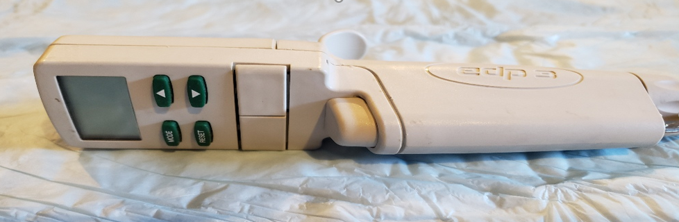
Recommended Equipment for EDP3-PlusPreventive Maintenance:
Laboratory gloves
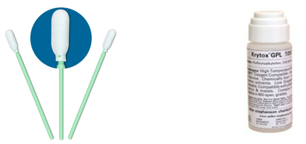
Krytox GPL-105 Oil (Pipette Supplies: RA 6100-065)
Foam Swabs for applying Krytox Oil & cleaning
Kim Wipes & 70% IPA
Replacement PM parts (as needed): Seal, O-Ring, Shaft
Small-bladed flat head and Phillip screwdrivers
Step 1:
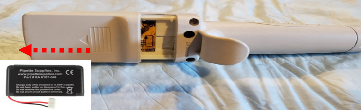
Remove the battery from the EDP3-Plus to lock the motor in the home position and to prevent movement during preventive maintenance. This is accomplished by sliding the battery door upward and disconnecting the battery from the battery port.
Step 2:
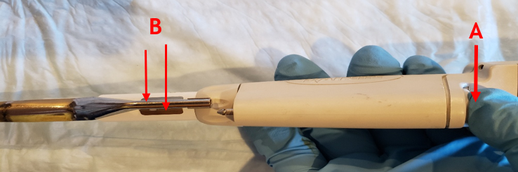
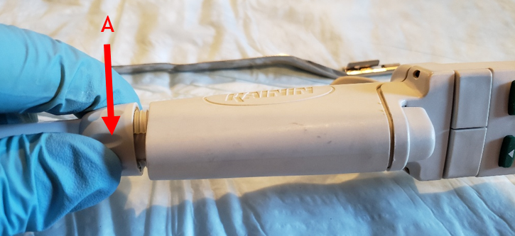
Press down the tip ejector button (A), then press down on the tip ejector clips (B) to disengage the tip ejector from the pipette. Lay the tip ejector arm a side for reassembly later.
Step 3:
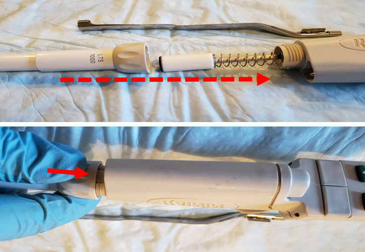
Unscrew and fully remove the coupling nut (A) from the pipette
CAUTION: There is an internal piston spring that may cause the seal and o-ring to shoot out of the shaft when removed. Be alert for parts that might pop off.
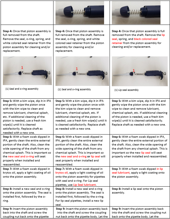
Step 4:
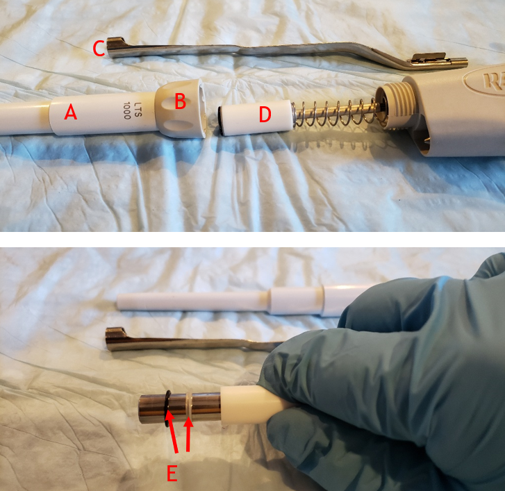
Ensure that the following parts are accounted for after removing the shaft from the pipette
A. White shaft B. Tan coupling nut C. Tip ejector arm D. Piston assembly w/ spring E. Seal and o-ring
CAUTION: There is an internal piston spring that may cause the seal and o-ring to shoot out of the shaft when removed. Be alert for parts that might pop off.
Step 5:
With the seal and o-ring removed, clean/wipe the piston with a clean kim wipe to remove any lubricant, chemical splash, or debris, from the piston.
IMPORTANT: Only wipe the piston once with the kim wipe and discard. If additional wiping is needed, use a fresh kim wipe for each additional wipe to prevent scratching the piston.
Step 6:
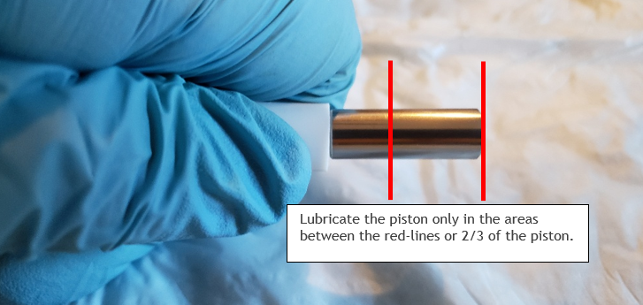
Once the piston is fully cleaned, apply a minute amount of Krytox oil onto a foam swab. Lightly coat the piston with the Krytox oil in between the red lines, as shown to the left (only 2/3 of the piston).
Step 7:
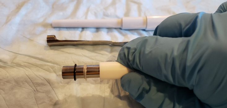
Install a new seal on the piston followed by the black o-ring on the piston, as shown.
NOTE: Pay attention to the orientation of the seal when installing onto the piston. Clean/replace the shaft as needed.
Step 8 Reassembly:
Once the seal and o-ring are installed onto the piston, place the coupling nut onto the shaft, as shown.
Step 9:
Screw the shaft and shaft coupling nut onto the pipette body until it is fully threaded and secure.
Step 10:
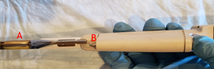
Reattach the tip ejector arm (A) until it clicks back into place on the ejector rod (B).
Step 11:
Allow the pipette to equilibrate at least 60 minutes before verifying accuracy and precision. Recheck work as necessary.
Note: Adjusting the calibration on this pipette is performed only with proprietary software by RAININ. If the pipette is not accurate and/or precise after preventive maintenance, kindly recheck your work. If the seal, o-ring, shaft, and piston are in good condition, but the pipette is still out of tolerance, accuracy and/or precision wide, please contact the manufacturer as this is a discontinued pipette model.
Disclaimer: Any action you take using the information on this website is strictly at your own risk. The information herein does not constitute professional advice and is general in nature. We make no warranty that this information will meet your requirements, be safe, accurate, or error-free. Pipette Supplies, Inc. is not responsible for any errors or omissions, any results obtained from the use of this information, or any loss or damage arising out of the use of this information. This site is for educational purposes only. Fair Use: Copyright Disclaimer under section 107 of the Copyright Act of 1976, allows for “fair use” for purposes such as comments, criticism, teaching, scholarship, news reporting, and research. Fair use is permitted by copyright statute that might otherwise be infringing.
Unscrew and remove the tip cone locking cover. Remove the tip cone.
Turn piston counterclockwise and remove.
Remove the operation button by pulling up.
Turn the adjustment wheel counterclockwise to reveal the small Phillips-type screw.
Remove the screw and ID Window.
Pull out the upper part of the top cover. Use your thumb to push, if necessary. Remove the top cover.
Use your thumbs to spread the back cover.
Remove the machinery.
Remove the battery and pull the connector out.
Assembly
Install the battery
Before installing the lower part, install the upper part of the machinery inside the battery cover.
Double check that the machinery was installed correctly.
Install the upper part of the top cover.
Use your thumb to push the cover down firmly. Press the lower part of the top cover to install it.
Re-screw the small Phillips-type screw under the adjustment wheel.
Install operation button. Bevel on the button should be on the same side as the finger grip, then notches will go into the groves.
Disclaimer: Any action you take using the information on this website is strictly at your own risk. The information herein does not constitute professional advice and is general in nature. We make no warranty that this information will meet your requirements, be safe, accurate, or error-free. Pipette Supplies, Inc. is not responsible for any errors or omissions, any results obtained from the use of this information, or any loss or damage arising out of the use of this information. This site is for educational purposes only. Fair Use: Copyright Disclaimer under section 107 of the Copyright Act of 1976, allows for “fair use” for purposes such as comments, criticism, teaching, scholarship, news reporting, and research. Fair use is permitted by copyright statute that might otherwise be infringing.
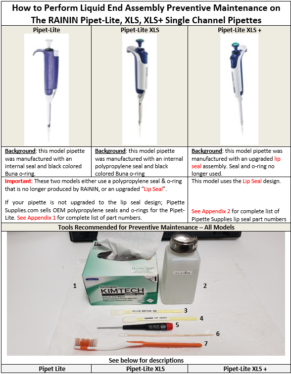
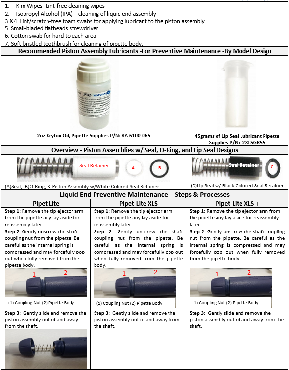
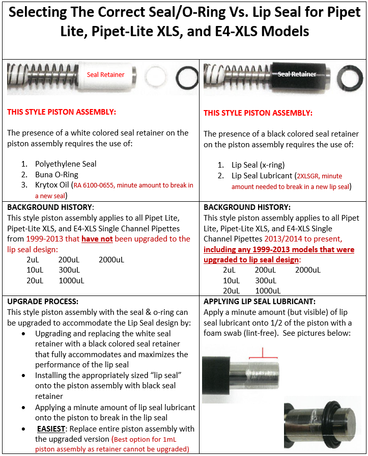
To perform Pipet-Lite preventative maintenance, you will need: Krytox Oil RA 6100-065 Lip Seal Lubricant 2XLSGR55
Disclaimer: Any action you take using the information on this website is strictly at your own risk. The information herein does not constitute professional advice and is general in nature. We make no warranty that this information will meet your requirements, be safe, accurate, or error-free. Pipette Supplies, Inc. is not responsible for any errors or omissions, any results obtained from the use of this information, or any loss or damage arising out of the use of this information. This site is for educational purposes only. Fair Use: Copyright Disclaimer under section 107 of the Copyright Act of 1976, allows for “fair use” for purposes such as comments, criticism, teaching, scholarship, news reporting, and research. Fair use is permitted by copyright statute that might otherwise be infringing.
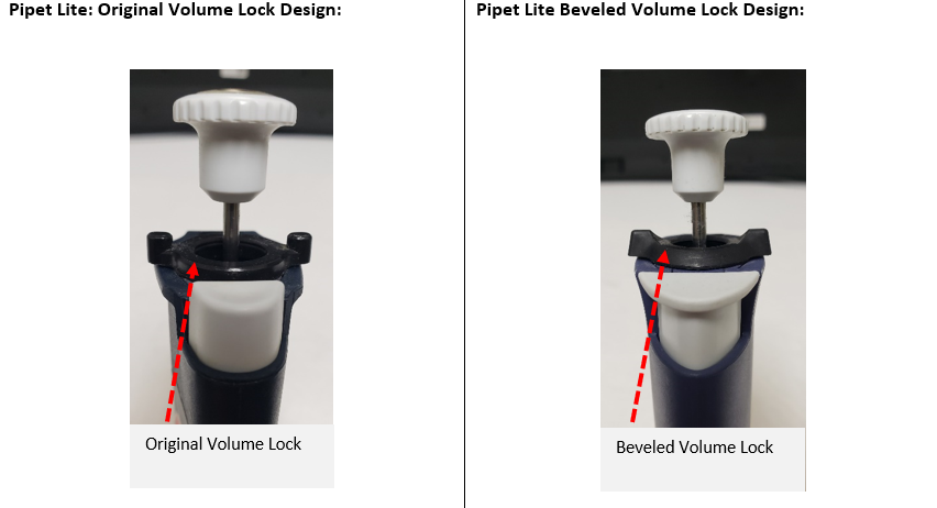
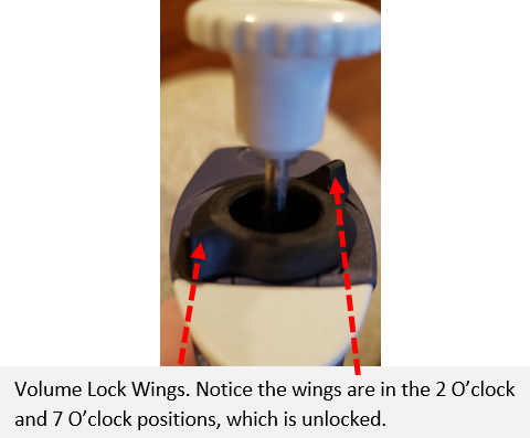
Step 1: Gently unlock the volume lock so the volume lock wings are in the 2 o’clock and 7 o’clock position.
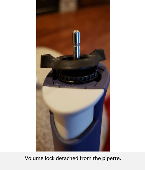
Step 2: With a small-bladed tool, gently pry up one of the volume lock wings until the volume lock detaches. Once detached, remove the plunger button.
Step 3: Remove the volume lock top and plunger button and lay aside for reassembly later.
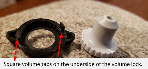
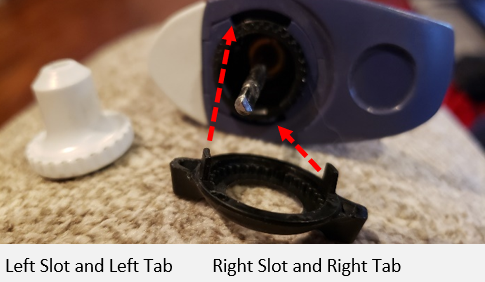
Note: Please note the square tabs on the underside of the volume lock for reassembly later.
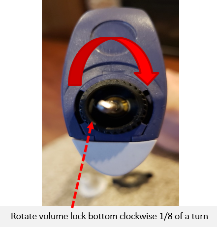
Step 4: Rotate the black colored volume lock base NO MORE THAN 1/8 of a turn clockwise to tighten a loose volume lock.
Note:
Rotate the volume lock base clockwise to tighten the volume lock.
Rotate the volume lock base counter-clockwise to loosen a hard-to-turn or tight volume lock.
REASSEMBLY PROCESS
Step 5: Place one of the square tabs on the underside of the volume lock into the left slot on the pipette body and the other tab into the right slot on the body.
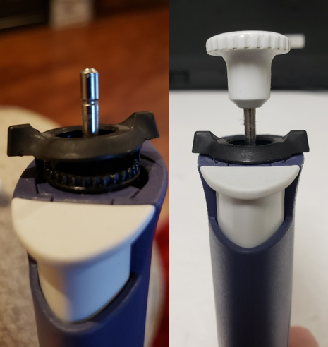
Step 6: Once aligned, press down, and snap the volume lock into place.
Then rotate the volume lock to the 3 o’clock and 9 o’clock position and re-install plunger button.
Note: If the Pipet-Lite volume lock is still loose, repeat the process until desired lock tension is achieved. Usually, 1/8 of a turn of the volume lock base is more than sufficient.
Disclaimer: Any action you take using the information on this website is strictly at your own risk. The information herein does not constitute professional advice and is general in nature. We make no warranty that this information will meet your requirements, be safe, accurate, or error-free. Pipette Supplies, Inc. is not responsible for any errors or omissions, any results obtained from the use of this information, or any loss or damage arising out of the use of this information. This site is for educational purposes only. Fair Use: Copyright Disclaimer under section 107 of the Copyright Act of 1976, allows for “fair use” for purposes such as comments, criticism, teaching, scholarship, news reporting, and research. Fair use is permitted by copyright statute that might otherwise be infringing.
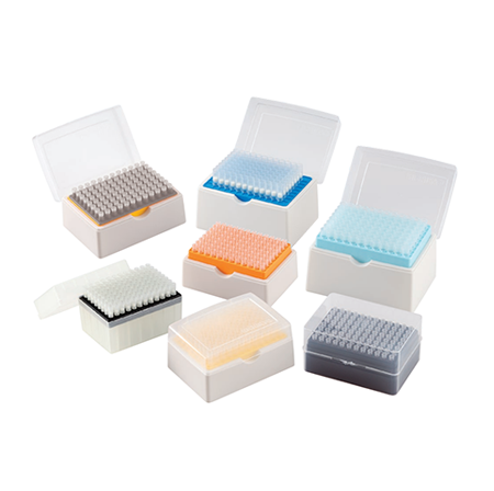
Pipette lingo can get confusing. Stay in the know with these different types of pipette tips.
Low Retention
Low retention tips are for applications requiring high accuracy and reproducibility. They reduce sample retention by 3-5 times when compared to ordinary tips. Good for use with samples that contain detergents.
Graduated Tips
These tips have scale lines along the tip, which makes it easy to infer the amount of liquid in the tip. Example: Indicators for 50μl, 100μl, 200μl.
Filter Tips
A small filter rests in the top of the tip to ensure no aerosols or liquid can reach the pipette shaft. Permeability is controlled by the pore size and filter length.
Extended Length/Elongated Tips
Designed to be used with narrow or deep vessels. They keep the pipette from touching the walls of the vessel and prevent cross-contamination.
Wide Orifice/Widebore Tips
The wide orifice prevents mechanical shearing that can cause cell fragmentation. These tips are good for use with cell suspensions and macromolecules (including DNA).
Universal Tips
Along with the tip manufacturer’s pipettes, these tips are also designed to fit *most* other manufacturer’s pipettes. Please note, these tips are not guaranteed to fit all other manufacturer’s pipettes.
ClipTip Tips
ONLY compatible with ClipTip pipettes (Thermo Fisher)
LTS Tips
ONLY compatible with LTS pipettes (Rainin)
Beveled Tips
These types of pipette tips have a sloped edge around the opening which reduces sample hang-up.
Disclaimer: Any action you take using the information on this website is strictly at your own risk. The information herein does not constitute professional advice and is general in nature. We make no warranty that this information will meet your requirements, be safe, accurate, or error-free. Pipette Supplies, Inc. is not responsible for any errors or omissions, any results obtained from the use of this information, or any loss or damage arising out of the use of this information. This site is for educational purposes only. Fair Use: Copyright Disclaimer under section 107 of the Copyright Act of 1976, allows for “fair use” for purposes such as comments, criticism, teaching, scholarship, news reporting, and research. Fair use is permitted by copyright statute that might otherwise be infringing.
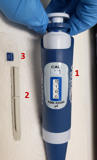
WARNING: Performing a calibration adjustment on any pipette should always be the last resort. Visual and performance confirmation that the internal seal, o-ring, piston assembly, lubricant (as applicable), shaft assembly, and other vital pipette parts that impact the accuracy and precision performance of the pipette must be in good/optimal working condition. Failure to recognize and replace worn parts could have an impact and shorten the life span of the pipette, possibly leading to costly repairs. Performing a calibration adjustment without confirmation of good pipette parts is a short-term solution at best.
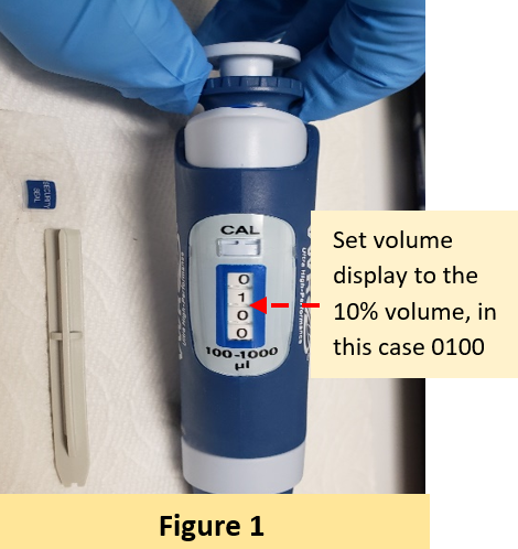
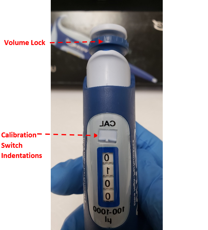
Set the pipette volume display to the 10% volume (i.e., for a 1000uL pipette, set to 100uL, see figure 1).
Note: It’s strongly recommended to perform any calibration adjustment at the 10% volume. This is where most pipette manufacturers perform their calibration adjustments due to linearity and uniformity (i.e., accuracy and precision).
Performing a calibration adjustment at any other volume than 10% may have a greater impact and skew the volume aspirated and dispensed at different volumes.
Step 2:
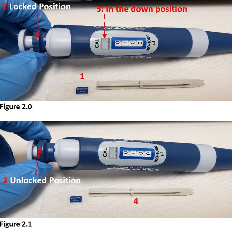
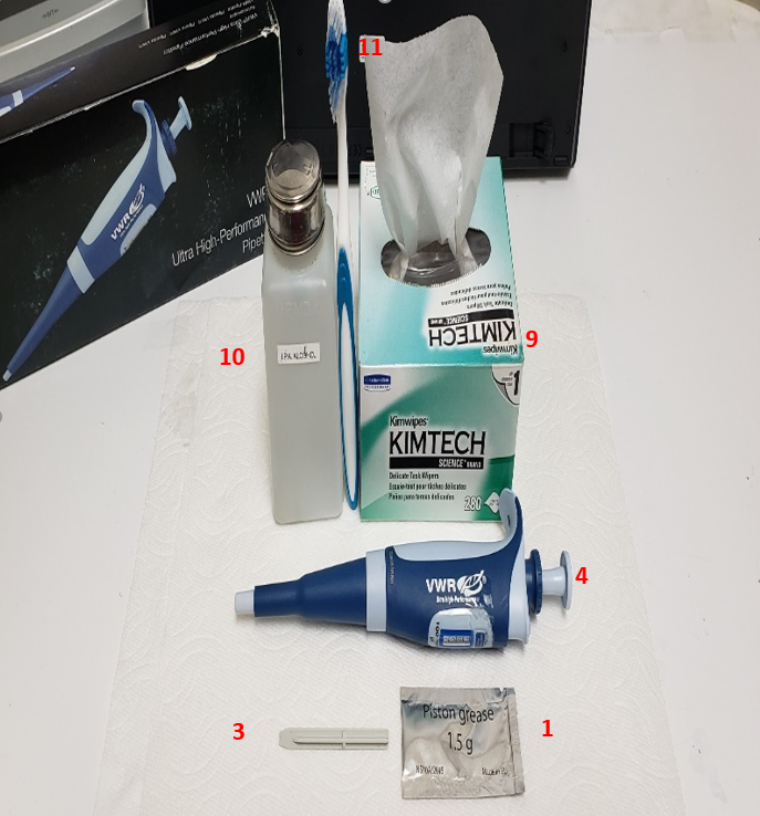
Remove the calibration concealment decal (#1) with a small-bladed tool. Lay aside for re-installment later. See figure 2.0
Important Note: Verify that the two calibration switch indentations (#3) beneath the word CAL on the pipette body is in the down position, as shown in figure 2.0. If found in the up position, push the indentations into the down position with the calibration tool (# 4, per figure 2.1) prior to executing step 3.
Step 3:
Pull the blue colored volume lock (#2) from the locked position (down position, see figure 2.0) to the unlocked position (up position as shown in figure 2.1.)
Step 4:
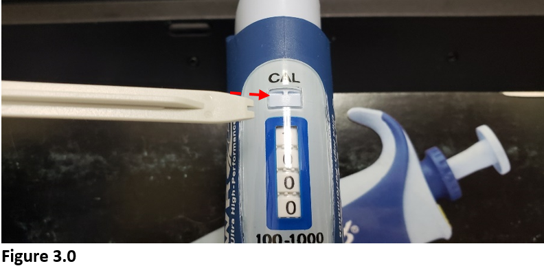
With the volume lock in the up position (unlocked), insert the calibration tool into the calibration switch indentations and move the indentations into the up unlocked position. See Figure 3.0
CAUTION: At this point, the pipette calibration mechanism is now in the unlocked position and vulnerable to any adjustments of the volume lock.
Step 5:
To adjust/calibrate the UHP pipette, Rotate the volume lock until the displayed volume matches the mean volume that was aspirated and dispensed.
Step 6:
Push the volume lock in the down position and calibration switch indentations back to the down position.
Step 7:
Check your calibration adjustments on a 4-5 place gravimetric balance. Repeat process until pipette is within acceptable tolerances for both accuracy and precision.
Step 8:
Reapply the calibration concealment decal to the pipette.
Disclaimer: Any action you take using the information on this website is strictly at your own risk. The information herein does not constitute professional advice and is general in nature. We make no warranty that this information will meet your requirements, be safe, accurate, or error-free. Pipette Supplies, Inc. is not responsible for any errors or omissions, any results obtained from the use of this information, or any loss or damage arising out of the use of this information. This site is for educational purposes only. Fair Use: Copyright Disclaimer under section 107 of the Copyright Act of 1976, allows for “fair use” for purposes such as comments, criticism, teaching, scholarship, news reporting, and research. Fair use is permitted by copyright statute that might otherwise be infringing.
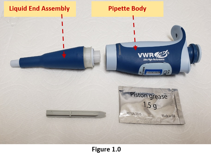
Carefully unscrew the liquid end assembly from the pipette body as shown in Figure 1.0.
Lay aside the pipette body for reassembly after preventive maintenance is completed.
Step 2:
Carefully unscrew the liquid end coupling nut from the tip ejector sleeve as shown in Figure 2.0.
Note: In Figure 2.0, you start to see the shaft assembly being exposed.
Step 3:
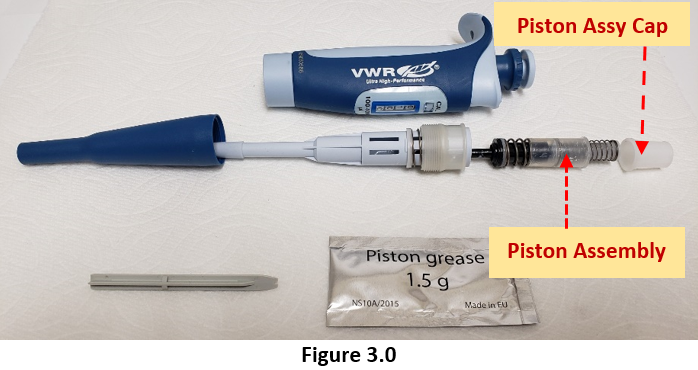
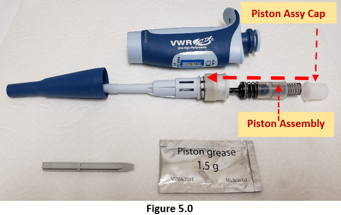
Carefully unscrew the piston assembly cap from the shaft assembly, per Figure 3.0
CAUTION: Be careful when unscrewing the piston assembly cap as the internal piston spring and components are under tension and may pop out.
Step 4:
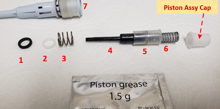
With the piston cap removed, the piston assembly and components are now visible for inspection, cleaning, preventive maintenance, and replacement as needed.
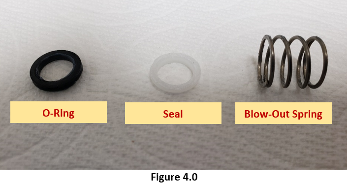
O-ring
Seal
Blow-out spring
Piston
Piston Retainer
Stroke Spring
Helpful Tip: Parts 1 through 6 comprise what is commonly referred to as the piston assembly.
Note:
At this stage, carefully inspect parts 1 and 2. These are one of the most critical components of the entire pipette and should be inspected, cleaned, and/or replaced routinely.
With a Kimwipe or lint-free towel and 70% IPA, remove any lubricant, debris, or chemical splash from the piston assembly (# 1 – #6) and the inside/outside of the shaft (#7).
Seals: replacement once every 12 months, based on usage
O-rings: replacement once every 12 -24 months, based on usage
Step 6A:
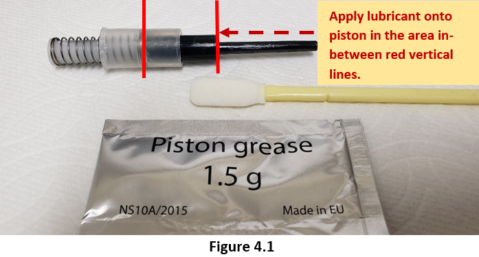
Once fully cleaned, apply a minute, but visible amount of piston lubricant (see page 1, PM Supplies Needed Section for part numbers) to a foam swab (DO NOT use cotton swabs as tiny stands of cotton may come off and mix with the lubricant).
Step 6B:
Carefully place a visibly light coat of lubricant onto the piston and retainer. Do not over apply the lubricant as accuracy and precision could be affected. See Figure 4.1.
Step 7:
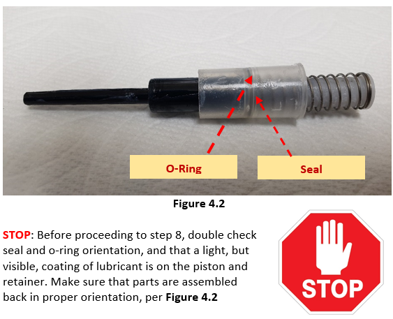
Install the new seal onto the piston, followed by the o-ring. See Figure 4.2
Note: It is very important that the seal is installed first, followed by the o-ring. DO NOT mix orientation, as it may affect accuracy and precision.
Step 8:
With a foam swab and 70% IPA, clean and swab the inside of the shaft to remove any debris, lubricant, or chemical splash that may have migrated inside of the shaft. Look for any visible wear, dullness, pit marks, or scratches on the shaft, ESPECIALLY in the area where the pipette tip seals to the shaft. Replace shaft as needed.
Pipette Reassembly After Completion of Preventive Maintenance
Step 9:
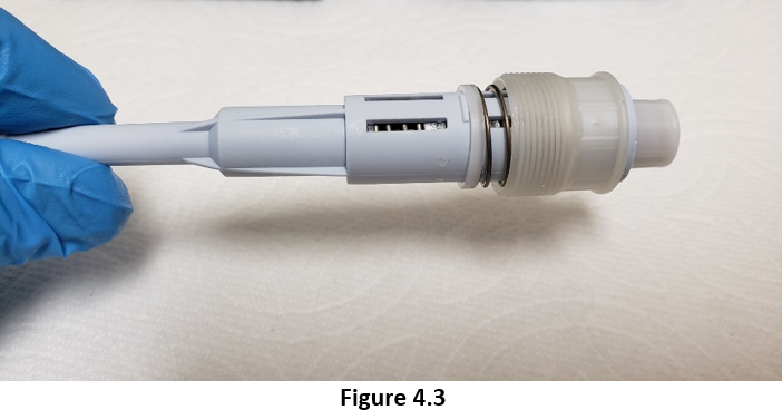
Place the piston assembly back inside the shaft. Carefully screw back on the piston assembly cap to secure the piston back inside the shaft as shown in Figure 4.3 above.
Step 10:
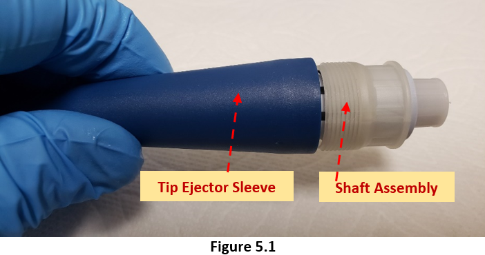
Clean and allow the tip ejector sleeve to fully dry. Once cleaned and dried, carefully screw the tip ejector sleeve back onto the shaft assembly as shown in Figure 5.1
Step 11:
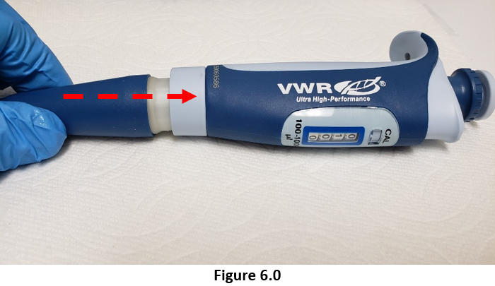
Carefully screw the tip ejector and shaft assemblies back onto the pipette body until snug. See Figure 6.0
Helpful Tips:
Once the UHP pipette is fully reassembled after preventive maintenance:
1. Set the pipette volume to nominal (100%), install a pipette tip and aspirate Di water into the tip. Carefully withdraw the pipette and tip from the water and allow the water to remain in the tip for 15 seconds. REASON: to look for any visible leakage of water dripping from the tip. If there are No leaks, allow pipette to equilibrate. If there are visible leaks, recheck your work.
2. Allow the UHP pipette to equilibrate for at least 60 minutes upon completion of preventive maintenance. REASON: Pipette needs to equilibrate back to ambient conditions. Conditions that were caused by performing PM (heat of our hands, etc.) impact overall pipette performance.
3. After 60 minutes of equilibration, confirm the accuracy and precision of the pipette on a 4-5 place analytical balance. On some occasions, a calibration adjustment may need to be made only after rechecking your work and confirming the parts and PM actions are sound/good.
Disclaimer: Any action you take using the information on this website is strictly at your own risk. The information herein does not constitute professional advice and is general in nature. We make no warranty that this information will meet your requirements, be safe, accurate, or error-free. Pipette Supplies, Inc. is not responsible for any errors or omissions, any results obtained from the use of this information, or any loss or damage arising out of the use of this information. This site is for educational purposes only. Fair Use: Copyright Disclaimer under section 107 of the Copyright Act of 1976, allows for “fair use” for purposes such as comments, criticism, teaching, scholarship, news reporting, and research. Fair use is permitted by copyright statute that might otherwise be infringing.
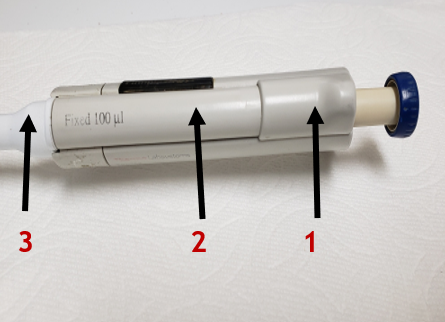
Finnpipette Digital Tip Ejector Pusher Mechanism: Based on imprinted volume size on mechanism. Does not include cog wheel or spring. Shop tip ejector pushers. Tip Ejector Spring – TS 1131820 Tip Ejector Button – TS 10593000 Cog Wheel – TS 10593060
(The Finnpipette Digital Single Channel is the same pipette as the Finnpipette Model 4500 Single Channel)
Background Overview:
Tip Ejector Button: Cog wheel is hidden from view and on underside of tip ejector button
Tip Ejector Pusher Mechanism: Ejector spring is hidden from view on underside of ejector pusher mechanism
White Colored Tip Ejector Sleeve: Ejector sleep fits over the shaft and allows the tips to be ejected.
Finnpipette Model 4500: How to Service and Replace the Tip Ejector Assembly
Step 1:
Gently pull downward on the white colored tip ejector sleeve until it disengages from the tip ejector assembly. Once removed, lay aside for reassembly later.
Step 2:
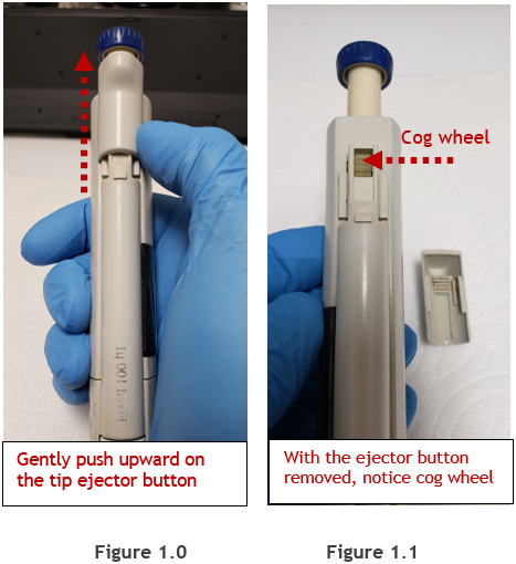
(Figure 1.0) Gently press upward on the tip ejector button with your thumb until it disengages from the lower portion of tip ejector mechanism. Once removed, lay the ejector button aside for reassembly later.
NOTE: (Figure 1.1) Notice the cog wheel is now visible once the ejector button is removed. Please be careful to not lose the cog when the tip ejector pusher mechanism is removed in step 3.
Step 3:
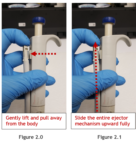
(Figure 2.0) Gently and carefully pull the upper portion of tip ejector pusher mechanism outward and away from the pipette body. Pull just enough so the cog wheel and upper portion of the ejector pusher mechanism no longer contacts the pipette body.
Step 4:
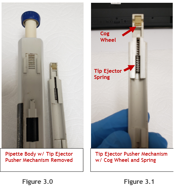
(Figure 2.1) While holding the cog wheel and upper portion of the ejector pusher assembly away from the pipette body, slide the entire ejector pusher mechanism upward to disengage it fully from the body. Once disengaged, lay aside, as shown in figure 3.0.
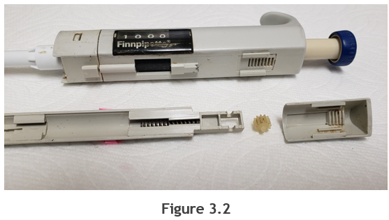
Note: In figures 3.0 and 3.1, notice the cog wheel and tip ejector spring positions/orientation. These parts can be removed for cleaning with 70% IPA and a soft bristled toothbrush. If needed, replacement parts can be found at Pipette Supplies:
Finnpipette Digital Tip Ejector Pusher Mechanism: PN: Based on imprinted volume size on mechanism and does not include cog wheel or spring. Shop tip ejector pushers.
Figure 3.2: Exploited view of the ejector button, cog wheel, tip ejector pusher mechanism, and spring removed from the pipette for easier viewing purposes.
Reassembly Process:
Step 5:
Re-install the tip ejector spring and cog wheel back onto the tip ejector pusher mechanism.
Step 6:
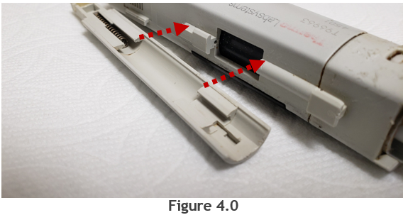
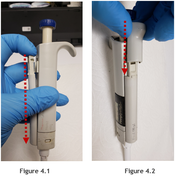
Align the tip ejector mechanism slits with the slots on the pipette handle, as shown in figure 4.0. Push the tip ejector pusher mechanism downward until it is fully seated back onto the pipette (Figure 4.1).
Step 7:
(Figure 4.2) Re-install the tip ejector button onto the tip ejector pusher mechanism by pushing downward.
Step 8:
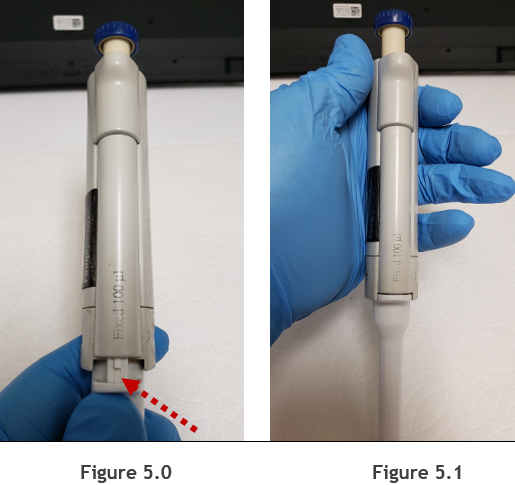
(Figure 5.0) Re-install the white colored tip ejector back onto the pipette by aligning it with the tip ejector pusher mechanism. Once aligned, push upward until it is secure.
Step 9:
(Figure 5.1) Check reassembly by loading and ejecting tips multiple times. Re-check your work as needed.
Disclaimer: Any action you take using the information on this website is strictly at your own risk. The information herein does not constitute professional advice and is general in nature. We make no warranty that this information will meet your requirements, be safe, accurate, or error-free. Pipette Supplies, Inc. is not responsible for any errors or omissions, any results obtained from the use of this information, or any loss or damage arising out of the use of this information. This site is for educational purposes only. Fair Use: Copyright Disclaimer under section 107 of the Copyright Act of 1976, allows for “fair use” for purposes such as comments, criticism, teaching, scholarship, news reporting, and research. Fair use is permitted by copyright statute that might otherwise be infringing.
Disclaimer: Any action you take using the information on this website is strictly at your own risk. The information herein does not constitute professional advice and is general in nature. We make no warranty that this information will meet your requirements, be safe, accurate, or error-free. Pipette Supplies, Inc. is not responsible for any errors or omissions, any results obtained from the use of this information, or any loss or damage arising out of the use of this information. This site is for educational purposes only. Fair Use: Copyright Disclaimer under section 107 of the Copyright Act of 1976, allows for “fair use” for purposes such as comments, criticism, teaching, scholarship, news reporting, and research. Fair use is permitted by copyright statute that might otherwise be infringing.