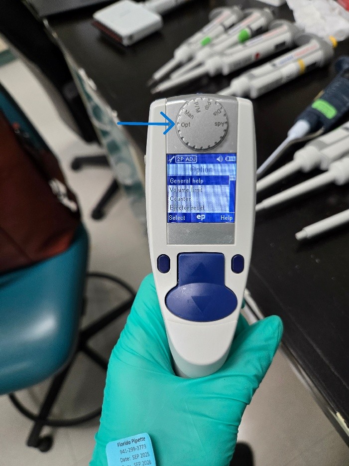
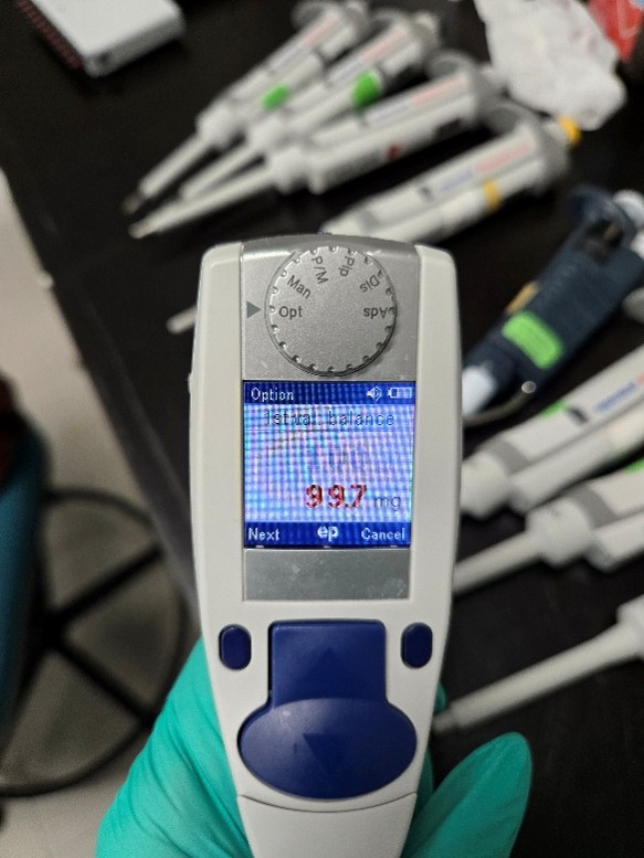
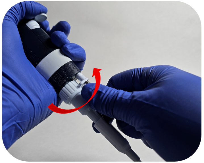
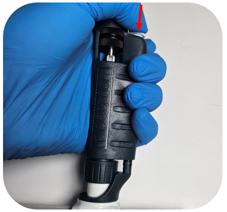
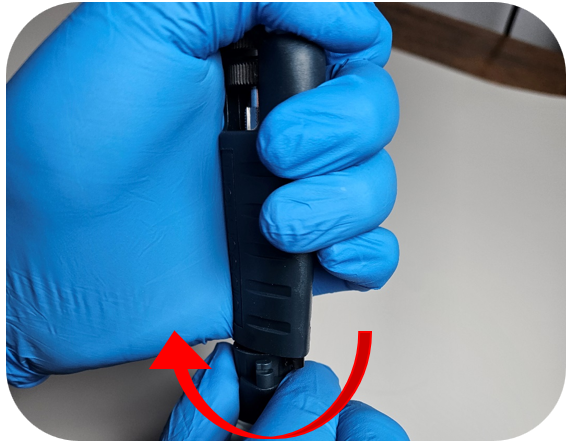
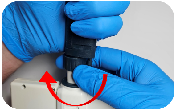
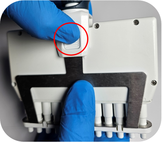
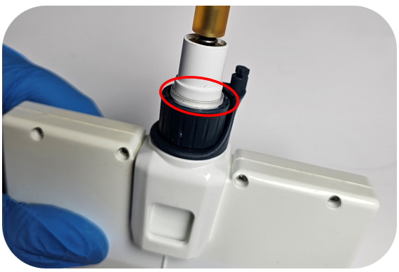
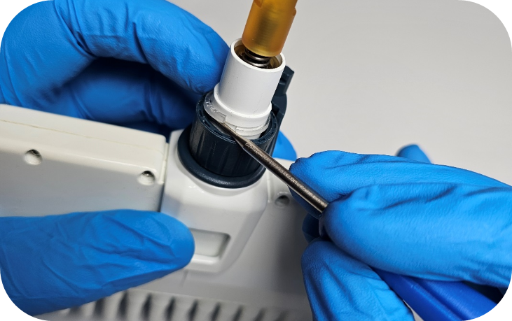
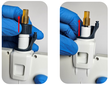
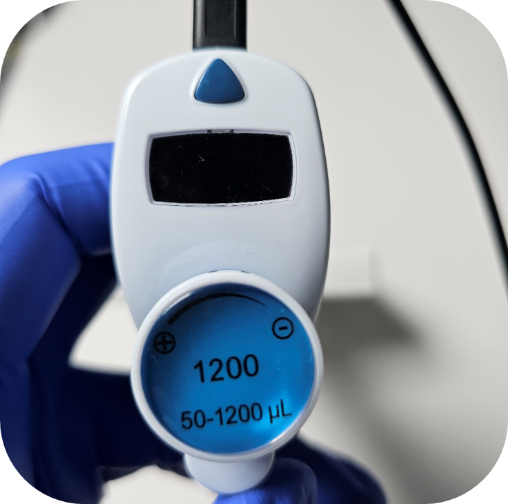
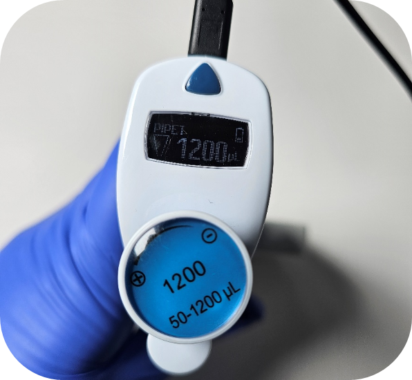
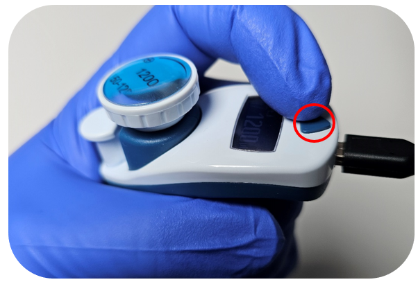
Toggle the Eppendorf Xplorer knob to ‘Opt’ (for Options)
Step 2:
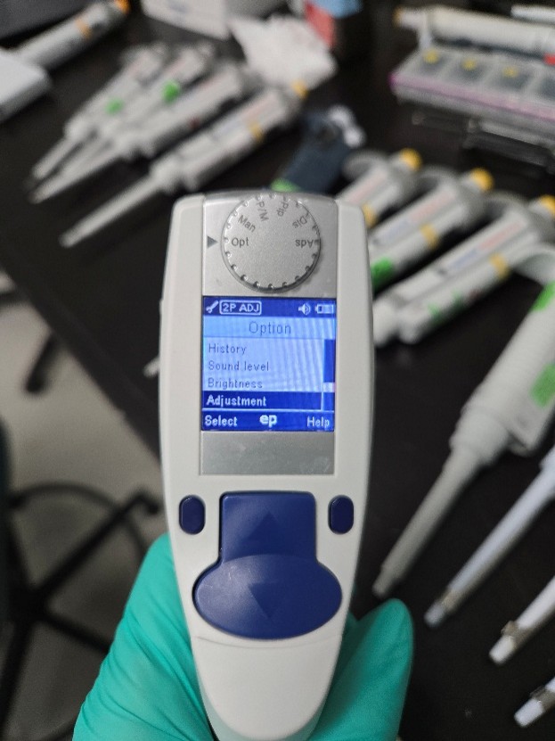
Use the up/down buttons to get to the ‘Adjustment’ option.
Step 3:
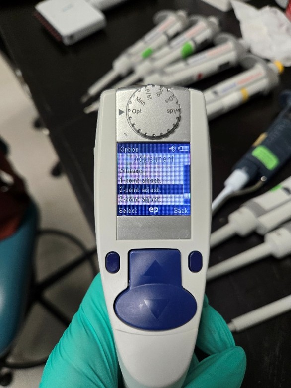
At this point you will have an option as to what type of adjustment you’d like to do. The options are 1-point, 2-point or 3-point. At this particular lab, they only needed testing at the high/low points so I selected 2-point adjustment.
Step 4:
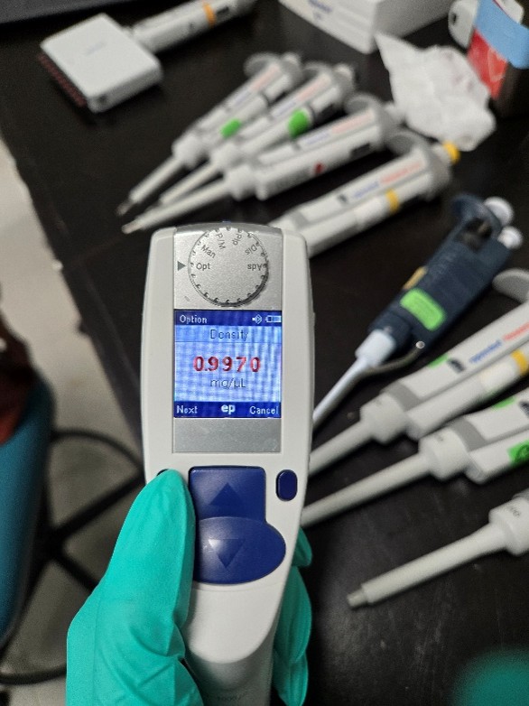
The first screen will ask you about the density of the water. You shouldn’t need to make any adjustments unless you are using something other than water. Click ‘Next’.
Step 5:
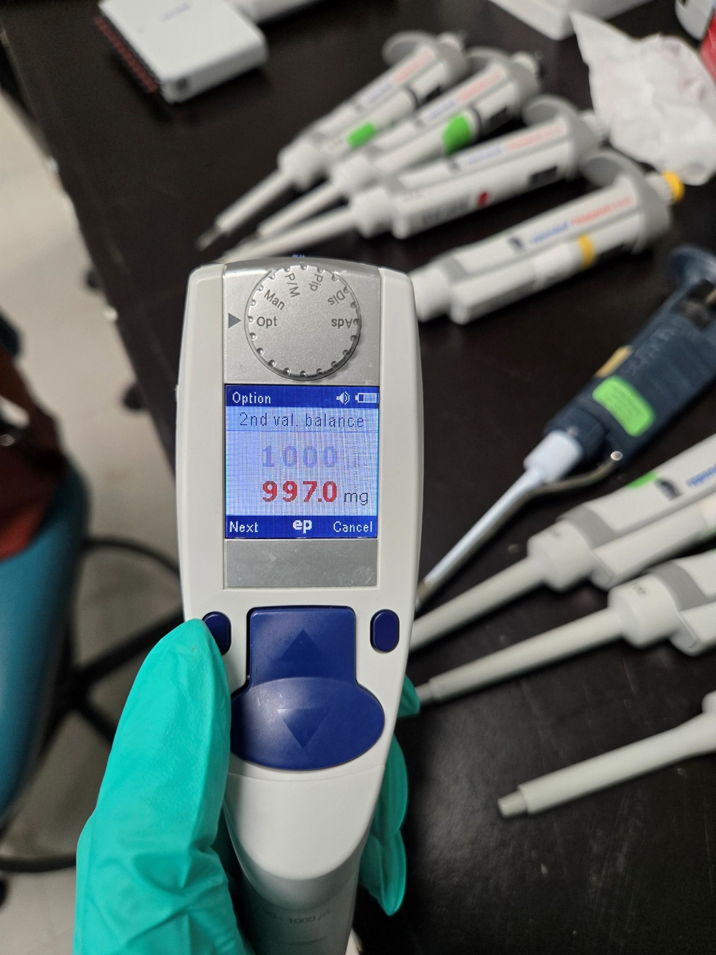
The next screen will show you what the volume should be and what it should be reading it mg. On a 2-point adjustment, the first volume it shows is the low reading. The volume will be in red. Click ‘Next’ and it will change the mg reading to red. Change the mg to what the pipette is currently reading at.
Example for a 1000ul: If your pipettes is reading at 89.0 at the low, set the mg reading to 89.0
Step 6:
The next option will be the high reading. Click ‘Next’ to get to the mg option and adjust to what the high volume is actually reading.
Step 7:
Once you adjust both readings it will give you the option to save the changes. Select ‘Yes’ and change the knob back to ‘Pip’. Let the pipette sit for a little while before testing, just like you would for manual pipettes.
Disclaimer: Any action you take using the information on this website is strictly at your own risk. The information herein does not constitute professional advice and is general in nature. We make no warranty that this information will meet your requirements, be safe, accurate, or error-free. Pipette Supplies, Inc. is not responsible for any errors or omissions, any results obtained from the use of this information, or any loss or damage arising out of the use of this information. This site is for educational purposes only. Fair Use: Copyright Disclaimer under section 107 of the Copyright Act of 1976, allows for “fair use” for purposes such as comments, criticism, teaching, scholarship, news reporting, and research. Fair use is permitted by copyright statute that might otherwise be infringing.
The repair process for a Research Plus multichannel nose cone replacement requires great care, a high attention to detail, patience, and steady hands. Please dedicate a good work area with good lighting and space where small parts can be located should they pop out during disassembly. If you don’t maintain attention to detail, you may damage the pipette and lose parts. Please proceed at your own risk.
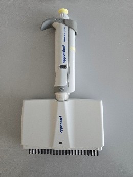
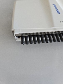
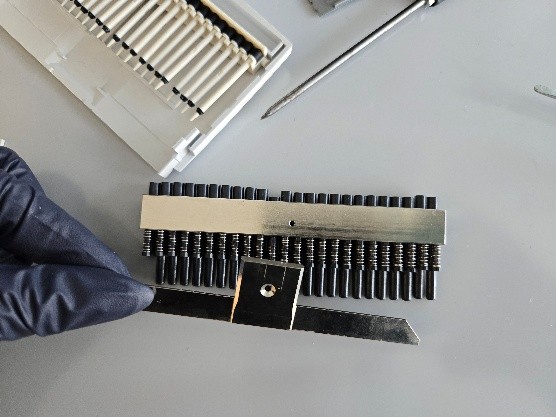
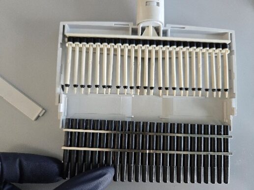
This is the 24-channel Eppendorf Research Plus. The first channel is broken off at the housing, so the entire channel needs to be replaced.
Step 1:
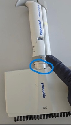
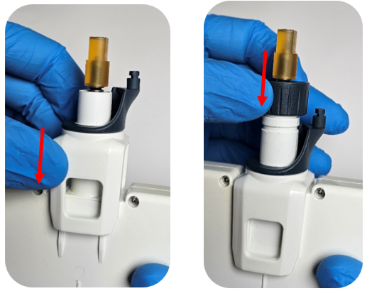
Begin by pulling this lever to the side to release the lower housing from the pipette body.
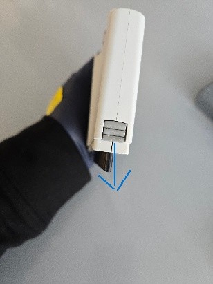
Open the housing by pulling the levers down to release the latch.
Step 2:
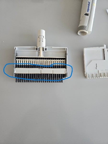
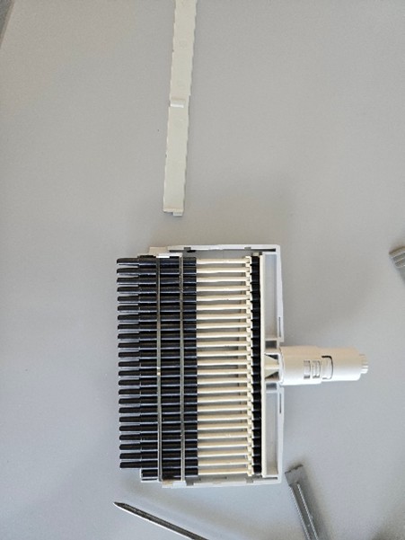
Once that is open, you’ll notice this plate that holds everything in place. Remove the plate (use a flathead screwdriver to help).
Step 3:
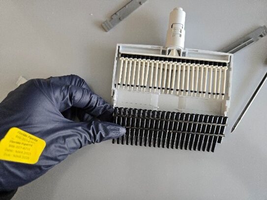
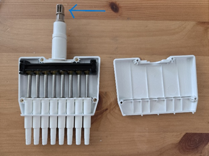
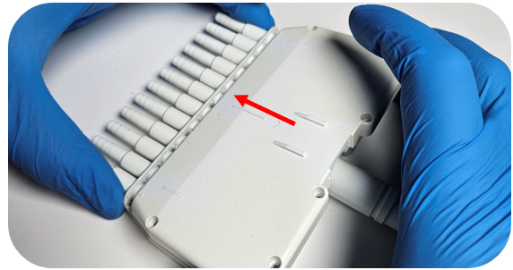
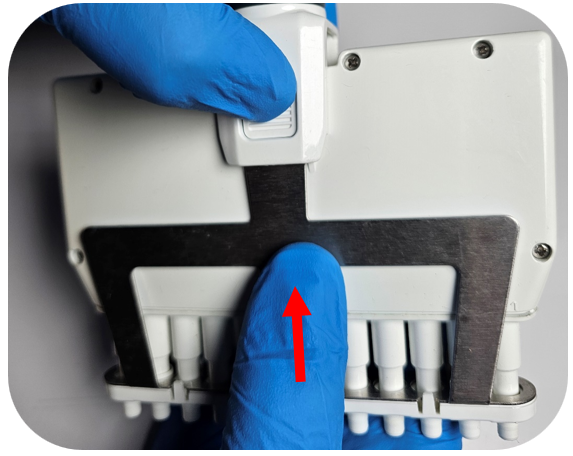
This entire lower unit is attached and will move together. The nose cones need to be removed entirely, which is done by sliding the unit down.
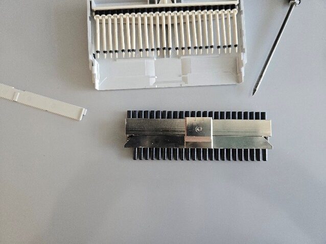
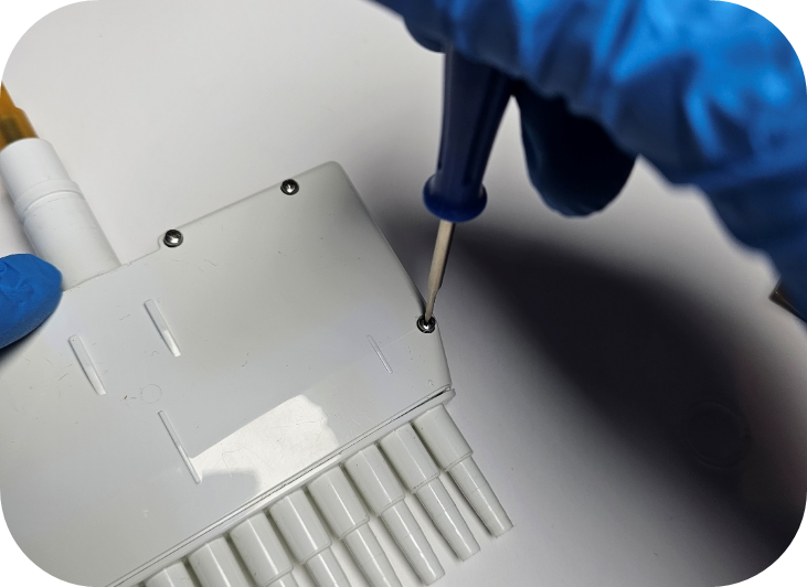
Once that is done, flip the entire unit over and you’ll see the screw that holds it all in place.
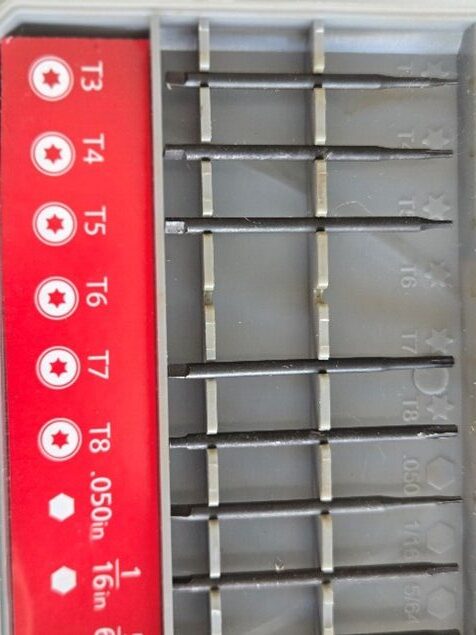
You will need a star screwdriver to remove the plate.
Step 4:
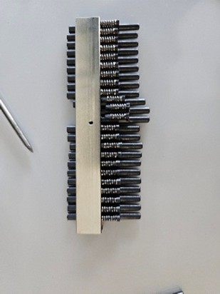
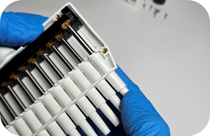
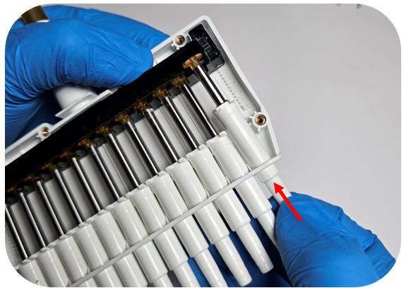
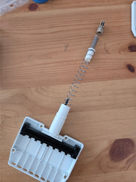
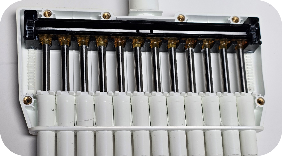
Once the plate is unscrewed you can remove it, but do so carefully because it is the only piece holding the nose cones in place. They will slide out easily. Be careful not to lose the springs that are attached to the nose cones.
NOTE: When you purchase a replacement nose cone, the spring is NOT included. You will need to use the one from the broken piece.
Step 5:
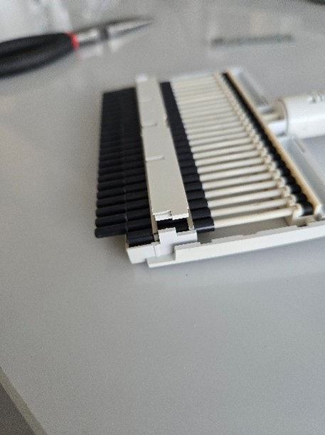
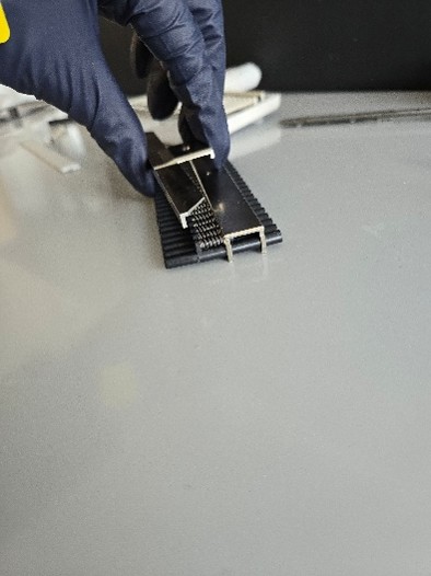
When you have replaced the nose cone, reattach the plate and screw it back in place. You’ll notice the bottom of the plate acts as a lip that holds the nose cones in place.
Step 6:
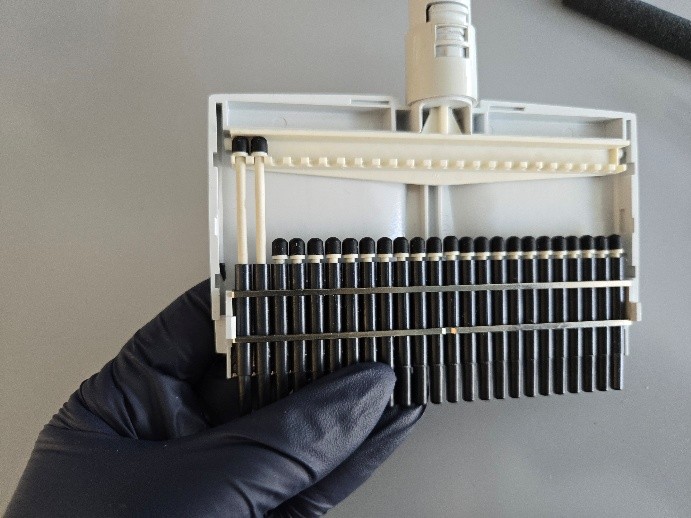
Once the plate is screwed back on, turn the assembly over so the screw is facing down. Carefully slide the nose cones back into the housing. All the nose cones must line up properly with the pistons or you will risk breaking a piston.
Another way to tackle this is to remove each piston and insert it into the nose cone first, once the nose cones are back in place, raise each piston individually and hook the back into the housing.
Step 7:
Reassemble the housing and reattach the housing to the body. It will snap back into place like a Research Plus single channel.
Disclaimer: Any action you take using the information on this website is strictly at your own risk. The information herein does not constitute professional advice and is general in nature. We make no warranty that this information will meet your requirements, be safe, accurate, or error-free. Pipette Supplies, Inc. is not responsible for any errors or omissions, any results obtained from the use of this information, or any loss or damage arising out of the use of this information. This site is for educational purposes only. Fair Use: Copyright Disclaimer under section 107 of the Copyright Act of 1976, allows for “fair use” for purposes such as comments, criticism, teaching, scholarship, news reporting, and research. Fair use is permitted by copyright statute that might otherwise be infringing.
A U.S. federal agency that develops national measurement standards. NIST does not accredit laboratories. It provides the foundational measurement standards to which calibration results are traceable.
What this typically means for pipettes:
Calibration documentation should include:
• A statement of traceability to NIST • Identification of reference standards used (the traceability chain) • Evidence of controlled measurement processes
Traceability to NIST establishes the measurement foundation beneath your documentation.
CLIA
Clinical Laboratory Improvement Amendments
What it is:
A U.S. federal regulation governing laboratories that test human specimens for diagnosis or health assessment.
What it cares about:
Accuracy. Reliability. Quality control.
What this typically means for pipettes:
CLIA does not prescribe a defined calibration format. However, laboratories must be able to demonstrate:
• The pipette is properly maintained and calibrated • Ongoing tracking over time • Date of calibration • Equipment identification (serial or asset number) • Pass/Fail determination • Documentation of corrective action if out of tolerance
CLIA is outcome focused. It requires evidence that equipment is controlled, monitored, and maintained.
COLA
Commission on Office Laboratory Accreditation
What it is: A laboratory accrediting organization operating under the CLIA framework, commonly serving physician offices and smaller laboratories.
What it cares about: Defined procedures. Consistent documentation.
What this typically means for pipettes: Documentation expectations are generally similar to CLIA
COLA is outcome focused. It requires evidence that equipment is controlled, monitored, and maintained.
The Joint Commission
What it is:
An accrediting body for healthcare organizations and hospital laboratories.
The Joint Commission requires a defined maintenance and calibration program, including:
• A documented calibration and maintenance plan • Date of calibration • Equipment identification (serial or asset number) • Pass/Fail documentation • Traceability • Documentation of corrective action (if out of tolerance) • Evidence of program oversight
The Joint Commission is system focused. It evaluates whether your maintenance program is clearly defined and consistently followed, not just whether calibration occurred.
CAP
College of American Pathologists
What it is:
A laboratory accreditation organization that often exceeds baseline CLIA requirements.
What it cares about:
Defined intervals. Traceability. Data defensibility.
What this typically means for pipettes:
CAP requires a clearly defined maintenance and calibration program and the technical calibration data to support it:
• Calibration at defined intervals • Documented tolerances • Traceability to recognized standards • Equipment identification (serial or asset number) • As-Found (AF) and As-Left (AL) data, not just Pass/Fail • Statistical accuracy and precision values • Documentation of out-of-tolerance events
CAP inspections are typically checklist driven and may require detailed calibration data to support technical defensibility.
ISO/IEC 17025
What it is:
The international standard for testing and calibration laboratory competence.
When a calibration provider is ISO/IEC 17025 accredited, documentation typically includes:
• As-Found (AF) data • As-Left (AL) data • Defined tolerances • Measurement uncertainty • Traceability statements • Environmental conditions (if required) • Accreditation identification
The documentation carries international recognition when the accreditation body is an ILAC Mutual Recognition Arrangement (MRA) signatory.
This matters most in pharmaceutical, biotechnology, manufacturing, and global trade environments.
ISO 17025 Accreditation Status Variations
ISO 17025 Accredited via ILAC MRA Signatory
A third-party accreditation body has audited the laboratory and issued ISO/IEC 17025 accreditation. The accrediting body is a signatory to the International Laboratory Accreditation Cooperation Mutual Recognition Arrangement (ILAC MRA), providing international recognition of the accreditation and strengthening confidence in calibration results across regulatory jurisdictions. This distinction is particularly important in pharmaceutical, biotechnology, manufacturing, and international trade environments.
ISO 17025 Accredited (Non-ILAC MRA)
A third-party accreditation body has audited the laboratory and issued accreditation. However, the accreditation body may not be internationally recognized under the ILAC framework. Accreditation is verified, but international recognition may be limited.
ISO 17025 “Compliant”
The laboratory states its internal quality system aligns with ISO 17025 principles. There is no third-party accreditation audit. Documentation depth may vary and is not independently verified.
ISO 8655
What it is:
The international standard defining performance requirements and test methods for piston-operated volumetric apparatus (pipettes).
When calibration follows ISO 8655, documentation typically includes:
• Defined gravimetric test method • Defined test volumes • Calculated accuracy values • Calculated precision values • Comparison to maximum permissible error limits
ISO 8655 defines how the pipette should be tested. ISO/IEC 17025 defines whether the laboratory is competent to perform that testing.
GMP
Good Manufacturing Practice
What it is:
A regulatory framework governing pharmaceutical, biotechnology, and medical device manufacturing.
What it cares about:
Product quality. Process control. Risk mitigation.
What this typically means for pipettes:
• Controlled measuring devices • Defined calibration intervals • Traceability to national standards • Documented review process • Impact assessment if out of tolerance
Under GMP, the key question becomes: Could an inaccurate pipette affect product quality?
Documentation must support defensibility.
GLP
Good Laboratory Practice
What it is:
A framework governing non-clinical research and safety studies.
What it cares about:
Data integrity. Study validity.
What this typically means for pipettes:
• Evidence equipment was suitable for use • Retained calibration documentation • Traceability • Support for reproducible results
GLP protects the validity of reported data.
SOPs
Standard Operating Procedures
The governing internal documents that define how your organization operates.
What it cares about:
Consistency. Defined processes. Accountability. Documentation control.
Inspectors and auditors will evaluate: Are you following your own written procedures?
Regulations and accreditation standards establish minimum expectations. In many environments, failure to follow internal SOPs is a larger finding than the regulatory citation itself.
In Summary
While CLIA, CAP, ISO, GMP, and GLP provide the framework, your organization determines:
• The level of documentation required • Whether AF/AL data is required • Whether uncertainty statements are necessary • Whether ISO 17025 accreditation is mandated • Whether ILAC MRA recognition is required
Each laboratory has the responsibility to define what is appropriate based on:
• Risk level • Patient impact • Manufacturing impact • Research integrity • Customer requirements • International distribution
The key is not memorizing acronyms. It is understanding how they connect.
Regulations establish the framework. Accreditation verifies competence. NIST anchors traceability. SOPs define your Internal Standard.
Disclaimer: Any action you take using the information on this website is strictly at your own risk. The information herein does not constitute professional advice and is general in nature. We make no warranty that this information will meet your requirements, be safe, accurate, or error-free. Pipette Supplies, Inc. is not responsible for any errors or omissions, any results obtained from the use of this information, or any loss or damage arising out of the use of this information. This site is for educational purposes only. Fair Use: Copyright Disclaimer under section 107 of the Copyright Act of 1976, allows for “fair use” for purposes such as comments, criticism, teaching, scholarship, news reporting, and research. Fair use is permitted by copyright statute that might otherwise be infringing.
Gilson recently simplified their pipette model offerings to the Pipetman, Pipetman L, and Pipetman M.
The information below covers some additional changes in the lineup to assist with identification gaps missing from a previous post provided on identifying the Pipetman Classic product line.
See the previous post related to the first four iterations of the Gilson Classic lineup:
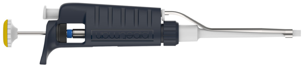
These two models are identical; the Pipetman G has simply been rebranded as the Pipetman. Gilson introduced the Pipetman in 2022, and its serial numbers start with T.
See the picture below for the Pipetman G & Pipetman:
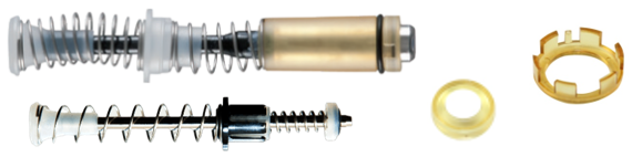
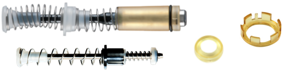
Seal Holder & Piston Assemblies:
Note: All sizes have a yellow seal holder with the exception of the 2µL (P2L).
Pipetman L:
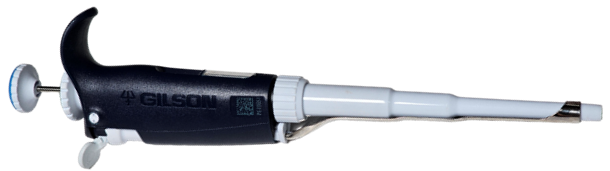
The presence of a finger hook and volume lock are the simplest indicators for identifying this model, as it was the first Gilson pipette to incorporate these features.
Seal Holder & Piston Assemblies:
Note: All sizes have a yellow seal holder with the exception of the 2µL (P2L).
My Pipetman:
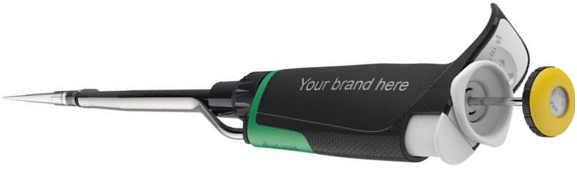
This uncommon model offers extensive color customization. Although most parts from the Pipetman L are compatible, they may not match the existing color scheme.
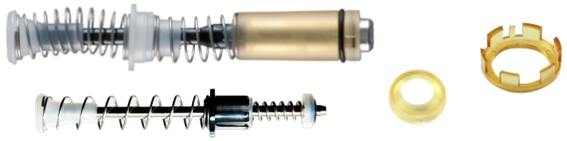
Seal Holder & Piston Assemblies:
Note: All sizes have a yellow seal holder with the exception of the 2µL (P2L).
Pipetman M:
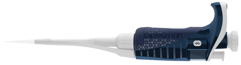
This is the sole electronic pipette in Gilson’s current product line. Two models are available: a standard version and a more recent, Bluetooth-enabled iteration. The connected model is designed for use with Gilson’s connected ecosystem (Trackman, PipettePilot, and Electronic Lab Notebook) and is identifiable by a Bluetooth symbol located on the side of the pipette body.
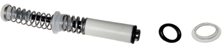
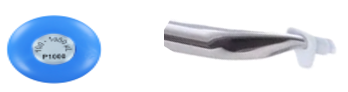
The last Classic model that was produced (started in June 2019, Serial #:QG-#####) utilized the Pipetman Neo parts. This included the piston assembly, updated button, and clip style tip ejector.
Neo piston assembly, seal, and o-ring.
Button & clip style tip ejector:
Disclaimer: Any action you take using the information on this website is strictly at your own risk. The information herein does not constitute professional advice and is general in nature. We make no warranty that this information will meet your requirements, be safe, accurate, or error-free. Pipette Supplies, Inc. is not responsible for any errors or omissions, any results obtained from the use of this information, or any loss or damage arising out of the use of this information. This site is for educational purposes only. Fair Use: Copyright Disclaimer under section 107 of the Copyright Act of 1976, allows for “fair use” for purposes such as comments, criticism, teaching, scholarship, news reporting, and research. Fair use is permitted by copyright statute that might otherwise be infringing.
The process of performing preventative maintenance for the Gilson Pipetman (formerly Pipetman G) and Pipetman L requires great care, a high attention to detail, patience, and steady hands. Please dedicate a good work area with good lighting and space where small parts can be located should they pop out during disassembly. Pipette damage and lost parts may occur if attention to detail is not maintained. Please proceed at your own risk.
The 2µL, 5mL, and 10mL models use the same seal and o-ring as the Pipetman Classic and Neo. Additionally, the Pipetman single channel has now replaced the Pipetman G. The new model uses the same parts as the Pipetman G.
Recommend Supplies:
Gloves
Cotton Swabs
Lint Free Wipe
Isopropanol (rubbing alcohol)
Step 1:
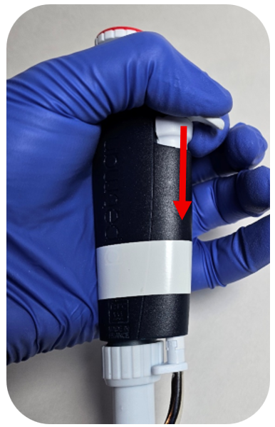
Press down the ejector button to expose the ejector clip.
Step 2:
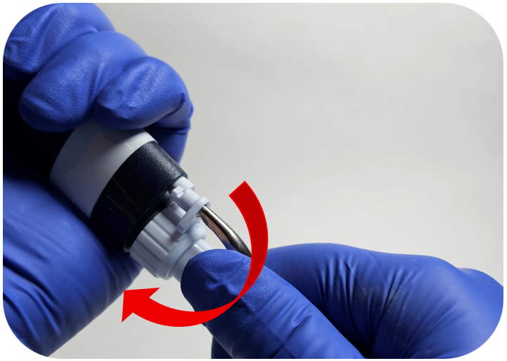
While holding the ejector button down, turn the tip ejector counterclockwise to unclip it.
Step 3:
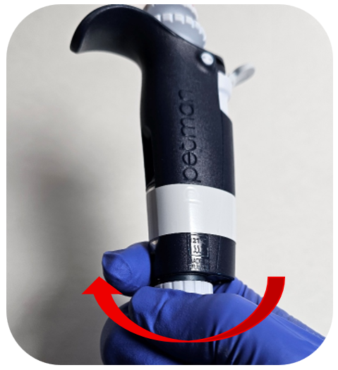
Turn the connecting nut counterclockwise to remove it from the pipette body.
Step 4:
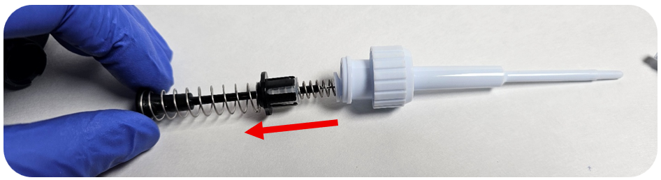
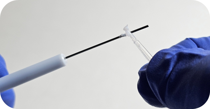
Remove the piston assembly from the tip holder.
Step 5:
Inspect the tip holder for any debris or seals/o-rings.
Step 6:
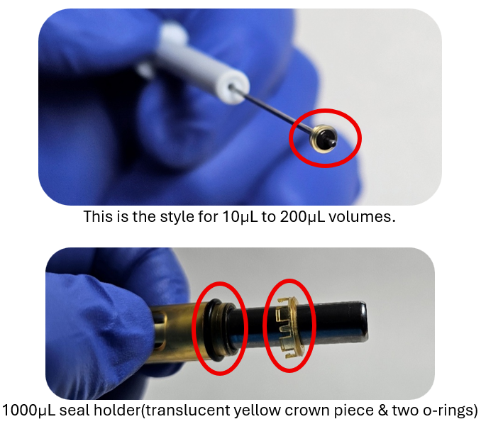
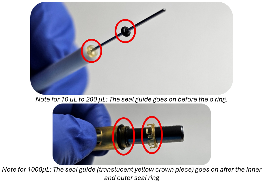
For 10µL to 1000µL models: Remove the seal guide and o-ring (or the inner and outer o-rings on the 1000 µL model) from the piston.
For 2µL, 5mL, and 10mL models: Remove the seal and o-ring from the piston.
Step 7:
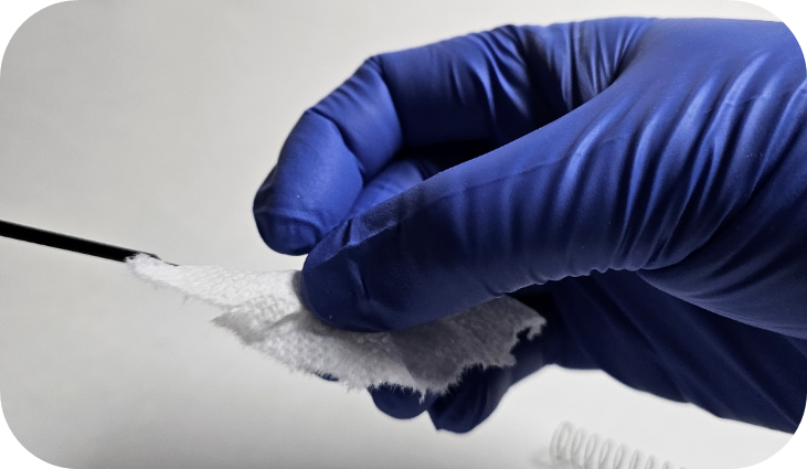
Clean the piston assembly using a lint free wipe moistened with isopropanol. Allow it to dry, then apply Gilson Pipetman G/L Grease.
Step 8:
For 10µL to 1000µL models: Install the seal guide and new o-ring (or inner and outer o-rings on the 1000µL model) onto the piston.
For 2µL, 5mL, and 10mL models: Install the new seal and o-ring onto the piston.
Step 9:
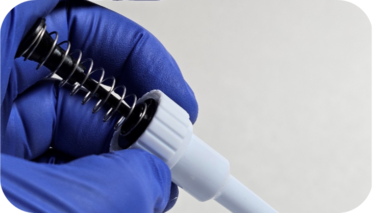
Reinsert the piston assembly into the tip holder and push it upward toward the pipette body.
For 5mL and 10mL models: Thread the tip cone onto the piston assembly.
Step 10:
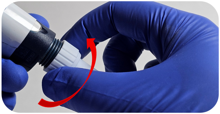
Turn the connecting nut clockwise to secure it to the pipette body.
Note: For 5mL and 10mL models, the piston assembly will thread directly into the pipette body.
Step 11:
While holding the ejector button down, turn the tip ejector clockwise to clip it into the ejector assembly.
Disclaimer: Any action you take using the information on this website is strictly at your own risk. The information herein does not constitute professional advice and is general in nature. We make no warranty that this information will meet your requirements, be safe, accurate, or error-free. Pipette Supplies, Inc. is not responsible for any errors or omissions, any results obtained from the use of this information, or any loss or damage arising out of the use of this information. This site is for educational purposes only. Fair Use: Copyright Disclaimer under section 107 of the Copyright Act of 1976, allows for “fair use” for purposes such as comments, criticism, teaching, scholarship, news reporting, and research. Fair use is permitted by copyright statute that might otherwise be infringing.
The process of removing, replacing, and reinstalling the lower assembly on the Gilson Pipetman Neo, G, & L multichannel pipettes requires great care, a high attention to detail, patience, and steady hands. Please dedicate a good work area with good lighting and space where small parts can be located should they pop out during disassembly. Pipette damage and lost parts may occur if attention to detail is not maintained. Please proceed at your own risk.
Note: A new version of the tip holder featuring V-rings is available. Please verify whether the Pipetman Multichannel pipette in question is equipped with this updated tip holder.
Recommend Supplies:
Gloves
Flat-head screwdriver
Phillip-head screwdriver
Preliminary Note(s): The instructions cover the 10uL, 20uL, 200uL & 300uL multichannel pipettes.
Step 1:
Press down the ejector button to expose the ejector clip.
Step 2:
While holding the ejector button down, turn the ejector interface counterclockwise to unclip it.
Step 3:
Turn the connecting nut counterclockwise to remove it from the pipette body.
Step 4:
Remove the tip ejector by pressing the clip located on either side of the ejector interface.
Step 5:
Ensure the connecting nut and ejector interface are in the down position. When both are down, the clear retaining clip should be visible.
Step 6:
Using a small flat-head screwdriver, locate the open end of the clear retaining clip. Gently apply upward pressure on the underside of the clip to remove it.
Step 7:
Once the clip is removed, detach the connecting nut and ejector interface from the lower assembly.
Step 8:
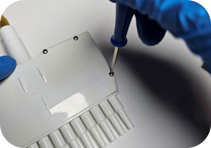
Remove all screws from the housing using a Phillips-head screwdriver.
Step 9:
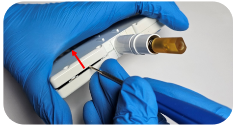
With the screws removed, carefully pry up the top section of the housing.
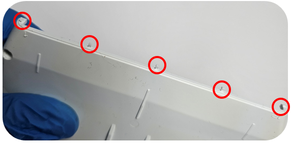
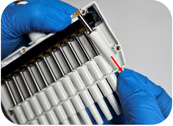
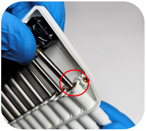
Note: Do not pry on the bottom end of the housing—plastic alignment tabs are located there and can be damaged. See the image below for the circled pin locations.
Step 10:
Lift up the top edge of the housing and pull it away from the bottom part of the housing to avoid damaging the plastic pins.
Step 11:
With the open side of the housing facing upward, press down on the tip holder to unseat the piston from the operating system.
Then push up on the tip holder to remove the piston assembly from the housing.
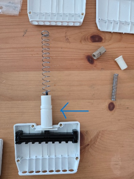
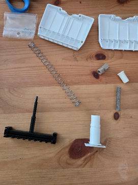
To Replace the Operating System / Manifold: In order to replace the housing you will need to remove the plunger, which can be done by unscrewing the top brown piece. Please USE CAUTION, there are two heavily wound springs being held in place by the screws and they will fly out if you are not keeping tension on the brown piece while unscrewing. Once the brown piece is unscrewed, remove the 2 springs from the top and the black plunger from the bottom. This white piece will also need to be removed from the old housing and clipped into the new housing. Place the black plunger into the housing and put both springs through the top and push down to screw the brown piece back in. Again, USE CAUTION because these springs will pop out if you’re not holding everything down with tension.
Step 12:
To reinstall the piston, insert the tip holder into the corresponding hole in the housing. While holding the tip holder, adjust the piston so it fits into the empty slot in the operating system.
Step 13:
Hold the top of the piston lightly in the operating system and align the tip holder tabs with the front and back housing channels. Apply gentle downward pressure on the tip holder to ensure it is fully seated.
Step 14:
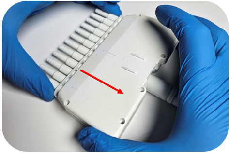
Before replacing the housing cover, confirm that the tops of the pistons are properly aligned (as shown below).
Step 15:
Insert the pins on the housing cover into the corresponding holes on the back half of the housing.
Step 16:
Press down on the top cover of the housing to ensure it is securely seated, then reinstall all screws using a Phillips-head screwdriver.
Step 17:
Attach the ejector interface to the top of the housing, followed by the connecting nut. Ensure all components remain in the down position.
Step 18:
Carefully press the clear retaining ring into place on the housing. You should feel a tactile “click” indicating it is fully locked.
Note: To confirm proper installation, pull gently on the connecting nut and ejector interface. If they cannot be removed, the retaining ring is correctly seated.
Step 19:
Reattach the connecting nut to the pipette body by turning the connecting nut clockwise.
Step 20:
Press down the tip ejector button and reclip the ejector interface by rotating the ejector interface towards the clip inside the pipette body.
Step 21:
Reinstall the tip ejector into the ejector interface, ensuring the ejector clips align with the grooves for a secure fit.
Disclaimer: Any action you take using the information on this website is strictly at your own risk. The information herein does not constitute professional advice and is general in nature. We make no warranty that this information will meet your requirements, be safe, accurate, or error-free. Pipette Supplies, Inc. is not responsible for any errors or omissions, any results obtained from the use of this information, or any loss or damage arising out of the use of this information. This site is for educational purposes only. Fair Use: Copyright Disclaimer under section 107 of the Copyright Act of 1976, allows for “fair use” for purposes such as comments, criticism, teaching, scholarship, news reporting, and research. Fair use is permitted by copyright statute that might otherwise be infringing.
The process of removing, replacing, and reinstalling the valve assemblies & Discharge Tubes on the BrandTech Dispensette S, S Organic, and S Trace requires great care, a high attention to detail, patience, and steady hands. Please dedicate a good work area with good lighting and space where small parts can be located should they fly out during disassembly. Pipette damage and lost parts may occur if attention to detail is not maintained. Please proceed at your own risk.
**This post is applicable to the following BrandTech Dispensette models: Dispensette S, Dispensette S Organic, and Dispensette S Trace
The discharge tube is available in two variants, one with a recirculation valve and one without. An easy way to determine which variant you have is to look for the knob on top of the discharge tube.
Preliminary Note(s): The Dispensette S, S Organic & S Trace models have discharge and filling valves threaded into the body of the bottletop, unlike the older models (Dispensette III & Dispensette Organic).
It is important to ensure the bottle top has been properly flushed with water prior to removing or replacing parts.
Discharge Tube Disassembly/Assembly:
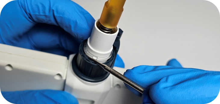
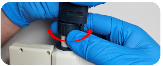
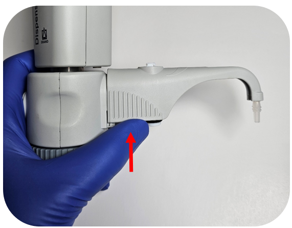
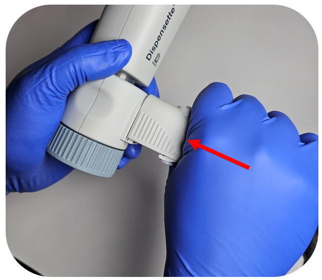
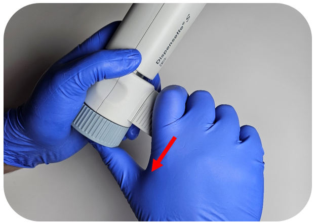
To remove the discharge tube, unseat the clips by applying upward pressure to the outer gray shell.
After the clips are unseated, pull the discharge tube away from the bottletop dispenser body while applying light downward pressure on the tube.
Note: The Dispensette S, S Organic, and S Trace Analysis models share the same discharge tube connection. However, it is recommended to use the correct part for each model, as there are differences in their use cases and specifications.
To reseat the discharge tube, firmly insert the tube(s) into their respective openings on the bottletop body until they are fully seated.
While keeping the inward pressure, push down on the discharge tube assembly until it clicks into place.
Discharge & Filling Valve Replacement:
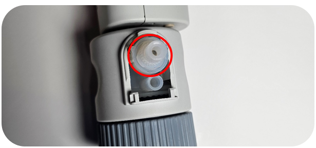
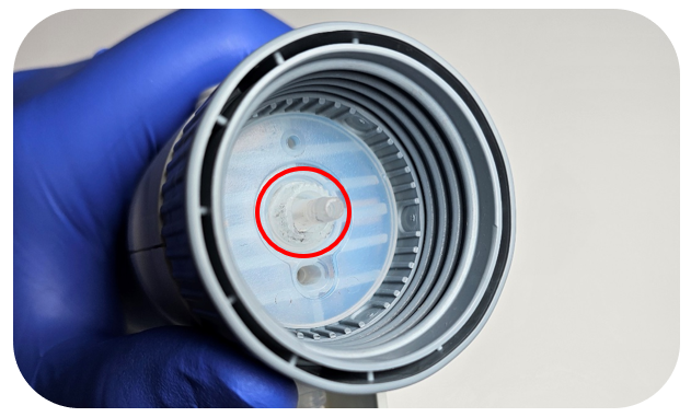
See the valve locations referenced in the pictures below:
Discharge Valve:
Filling Valve:
Note: The filling valve is more commonly clogged since it is positioned vertically, allowing solution to settle around the glass ball inside the valve. Refer to the instructions below to free the valve.
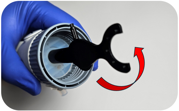
After locating the valve, use the mounting tool to remove it. Ensure the tool is fully seated, then unscrew the valve assembly by turning it counterclockwise.
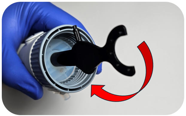
Next secure the new valve in the mounting tool and turn the valve clockwise to tighten. Be careful not to overtight the valve as you can strip the body of the bottletop.
Resetting A Stuck Valve:
It is fairly common for a valve to become stuck. This can occur in either the filling valve or the discharge valve, but the process to free it is simple.
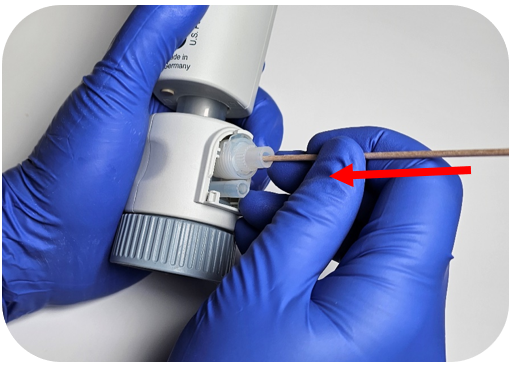
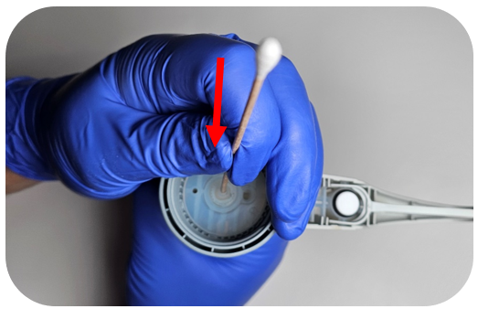
To free the valve, insert a 200 µL pipette tip or the wooden end of a 6-inch cotton swab (Q-Tip) into the valve opening. Apply gentle downward pressure to depress the glass ball inside the valve and release it.
This procedure resolves most issues with these bottletops. However, if the problem persists, the valve may need to be replaced.
Discharge Valve:
Filling Valve:
Note: This resetting procedure works for nearly all of the bottletop dispensers that BrandTech has made. The main difference is the older models do not have removeable valves.
Disclaimer: Any action you take using the information on this website is strictly at your own risk. The information herein does not constitute professional advice and is general in nature. We make no warranty that this information will meet your requirements, be safe, accurate, or error-free. Pipette Supplies, Inc. is not responsible for any errors or omissions, any results obtained from the use of this information, or any loss or damage arising out of the use of this information. This site is for educational purposes only. Fair Use: Copyright Disclaimer under section 107 of the Copyright Act of 1976, allows for “fair use” for purposes such as comments, criticism, teaching, scholarship, news reporting, and research. Fair use is permitted by copyright statute that might otherwise be infringing.
In this case, you may need to send the device a service technician for repair. The issue could be mechanical, possibly with the motor or lower assembly.
Disclaimer: Any action you take using the information on this website is strictly at your own risk. The information herein does not constitute professional advice and is general in nature. We make no warranty that this information will meet your requirements, be safe, accurate, or error-free. Pipette Supplies, Inc. is not responsible for any errors or omissions, any results obtained from the use of this information, or any loss or damage arising out of the use of this information. This site is for educational purposes only. Fair Use: Copyright Disclaimer under section 107 of the Copyright Act of 1976, allows for “fair use” for purposes such as comments, criticism, teaching, scholarship, news reporting, and research. Fair use is permitted by copyright statute that might otherwise be infringing.
The process of adjusting and troubleshooting leaks during calibration for the Eppendorf Reference 2 requires great care, a high attention to detail, patience, and steady hands. Please dedicate a good work area with good lighting and space where small parts can be located should they fly out during disassembly. Pipette damage and lost parts may occur if attention to detail is not maintained. Please proceed at your own risk.
Note: The 2.5µL, 10µL, & 20µL have seals that are built into the tip cone which would require the complete replacement of the lower assembly.
Recommend Supplies:
Gloves
Eppendorf Reference 2 adjustment tool: EP 3120633006
Note: Counter assembly issues are fairly common on the Reference 2 and can cause issues with making adjustments.
Step 1:
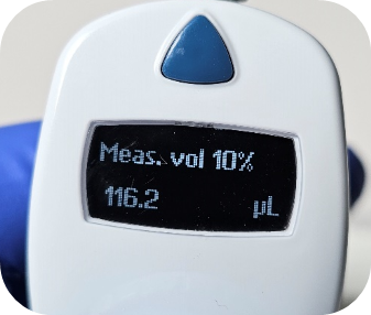
Set the pipette to 10% of the nominal volume and check its performance at this setting. If the pipette is operating outside of its specifications, record the value in microliters, as you will need it in Step 6. Refer to the most recent revision of the Reference 2 operating manual for your pipette’s specifications.
Step 2:
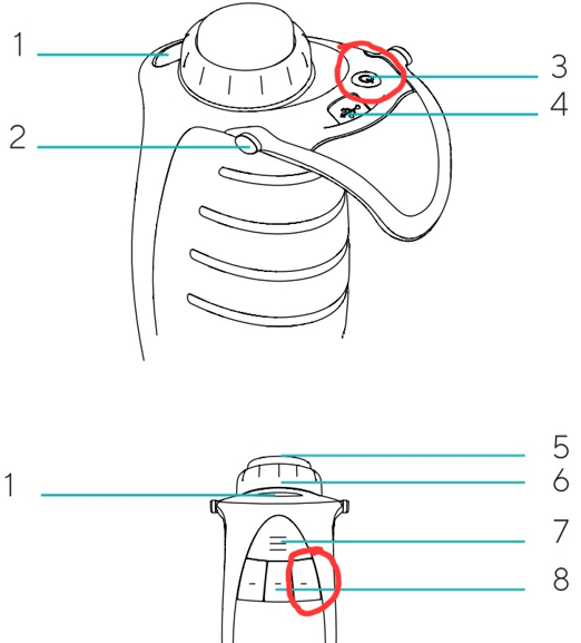
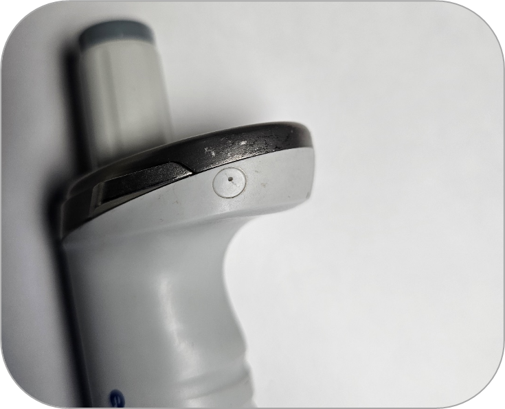
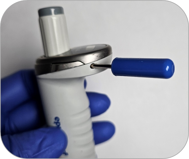
Locate the adjustment cap on the side of the pipette, near the volume catch.
Step 3:
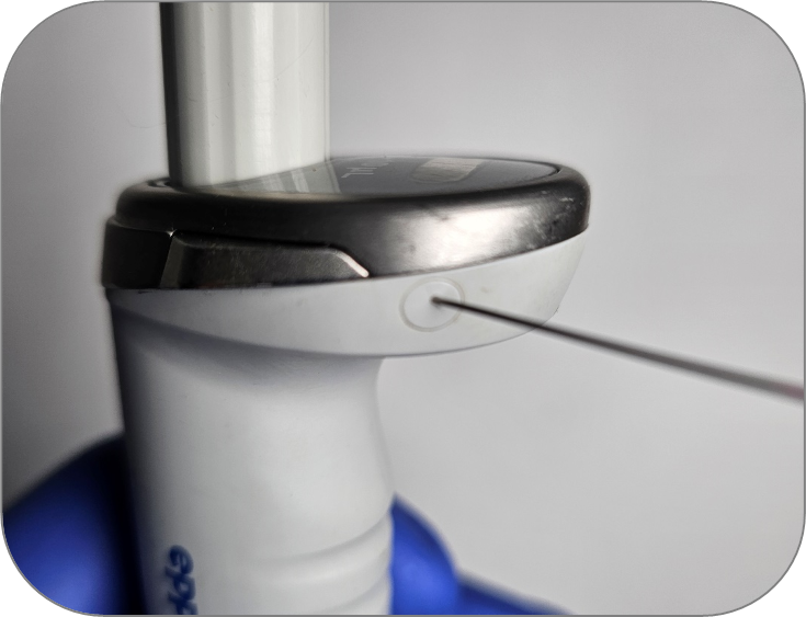
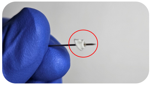
To remove the cap, insert a pin or push pin into the hole in the cap. In most cases, the pin will pass through the cap.
Note: Do not push the pin further in, as this could damage the counter.
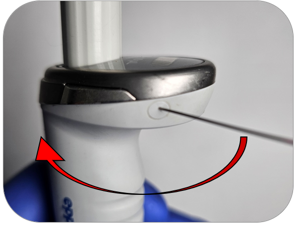
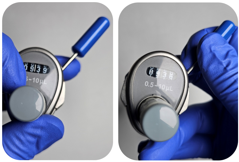
Step 4:
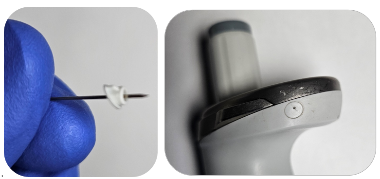
Once the pin is snug in the plastic cap, gently tilt the pin toward the volume catches. This will release the cap from the pipette body.
See the image below for reference.
Step 5:
Insert the Reference 2 adjustment tool into the hole where you removed the cap. Ensure the hex key aligns with the keyed hole.
Step 6:
Begin adjusting by holding the volume adjustment knob while turning the adjustment tool to the value you recorded in Step 1. Turning the tool clockwise decreases the volume, while turning it counterclockwise increases the volume.
Note: The volume adjustment knob tends to move during adjustments, so maintain a firm grip. If you notice binding or stripping in the adjustment mechanism, it is typically due to a counter issue. The adjustment mechanism should move with minimal effort. If a counter replacement is required, you can find the instructions at the following link:https://pipette.zenzen1.com/blog-eppendorf/eppendorf-reference-2-how-to-replace-the-volume-catch/
Step 7:
Recheck the pipette to confirm it is now operating within specification. If a leak is detected, check the tip holder and the seal/piston.
Step 8:
Once all adjustments are complete and the pipette is operating within manufacturer specifications at all volumes, reinstall the adjustment cap.
Note: The adjustment cap is keyed, so be sure to align the fin on the cap with the pipette body for a proper fit.
Disclaimer: Any action you take using the information on this website is strictly at your own risk. The information herein does not constitute professional advice and is general in nature. We make no warranty that this information will meet your requirements, be safe, accurate, or error-free. Pipette Supplies, Inc. is not responsible for any errors or omissions, any results obtained from the use of this information, or any loss or damage arising out of the use of this information. This site is for educational purposes only. Fair Use: Copyright Disclaimer under section 107 of the Copyright Act of 1976, allows for “fair use” for purposes such as comments, criticism, teaching, scholarship, news reporting, and research. Fair use is permitted by copyright statute that might otherwise be infringing.
Note: You do not need any special tools to complete the adjustment for the Gilson Pipetman M.
Recommend Supplies:
Balance
Pipette Tips
Step 1:
Make sure the pipette has enough battery life before proceeding to the next step.
Step 2:
Start by turning on the pipette by pressing down on the dispense button.
Step 3:
Prior to adjusting the pipette, collect 2-3 data points at each test volume (low, middle, and high) on the balance. The data will be used in Step 7.
Step 4:
After the data points have been collected, click on the blue triangle button.
Step 5:
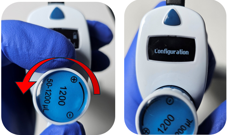
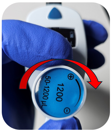
Turn the adjustment wheel counter-clockwise to “Configuration” and press down on the dispense button.
Step 6:
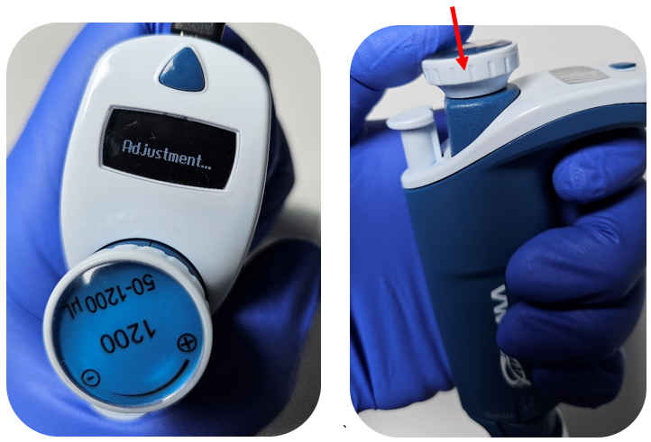
Turn the adjustment wheel counter clock-wise to “Adjustment” and press down on the dispense button.
Step 7:
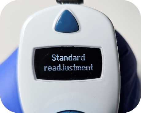
The standard readjustment utilizes a 3-point calibration (low, middle & high). Using the data collected in step 1, get an average value in microliters for each test volume.
Step 8:
Click the dispense button (the current setpoint value will flash) to modify the low point value and adjust to the calculated average value by turning the adjustment knob. Once the value is set, click the dispense button to lock in the value.
Step 9:
To move to the middle & high test points, turn the adjustment knob clockwise. Repeat the same process in step 8 for the middle and high averaged values.
Step 10:
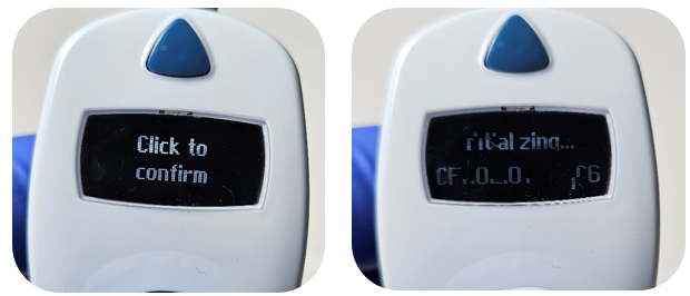
After all values are entered, turn the adjustment knob clockwise to “Click to confirm”. Click the dispense button. This will cause the pipette to restart.
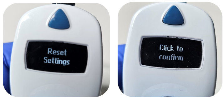
Note: There is an option to perform a factory reset of the calibrated values. To begin, complete steps 1 through 6. After completing step 6, turn the adjustment knob clockwise to select “Reset settings.” The prompt “Click to confirm” will appear on the screen. Press the dispense button to confirm and complete the factory reset.
Step 11:
Use the balance to check the pipette now that the adjustment has been made.
Disclaimer: Any action you take using the information on this website is strictly at your own risk. The information herein does not constitute professional advice and is general in nature. We make no warranty that this information will meet your requirements, be safe, accurate, or error-free. Pipette Supplies, Inc. is not responsible for any errors or omissions, any results obtained from the use of this information, or any loss or damage arising out of the use of this information. This site is for educational purposes only. Fair Use: Copyright Disclaimer under section 107 of the Copyright Act of 1976, allows for “fair use” for purposes such as comments, criticism, teaching, scholarship, news reporting, and research. Fair use is permitted by copyright statute that might otherwise be infringing.