Author: Pipette Supplies Team

  • Preventative Maintenance: VWR Ergonomic High-Performance (EHP) Single Channel Pipette

    The process of disassembly, removing, replacing, and reinstalling parts, as well as, performing preventive maintenance (PM) on the VWR EHP single channel pipette require great care. A high attention to detail, patience, and steady hands are required. Please dedicate a good work area with good lighting and space where small parts can be located should they pop/fly out during disassembly. Pipette damage and lost parts may occur if attention to detail is not maintained. Please proceed at your own risk.

    Recommended Supplies:
    1. Pair of gloves
    2. Bottle of 70% IPA
    3. Box of Kim Wipes
    4. VWR Piston 1.5g Grease: LN SP29019 1.5grams or LN SP29021 for 30g
    5. 1-2 foam swabs
    6. VWR EHP single channel replacement parts can be found here.

    Note: These instructions are applicable for the volume sizes 2uL-1mL of the VWR EHP single channel pipette.

    It’s recommended that a 4-5 analytical balance be used to check the accuracy and precision performance of the pipette after preventative maintenance, part replacement & reassembly, and 1 hour equilibration period is completed.
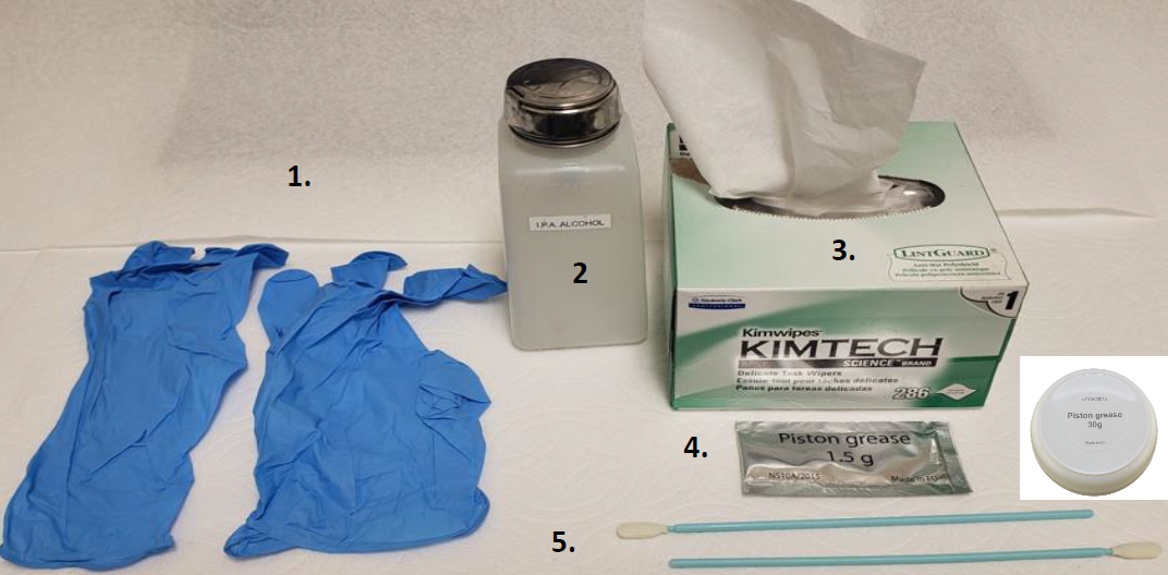
    Supplies needed
    Disassembly and Preventive Maintenance Process:
    Step 1:

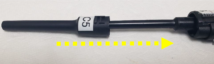
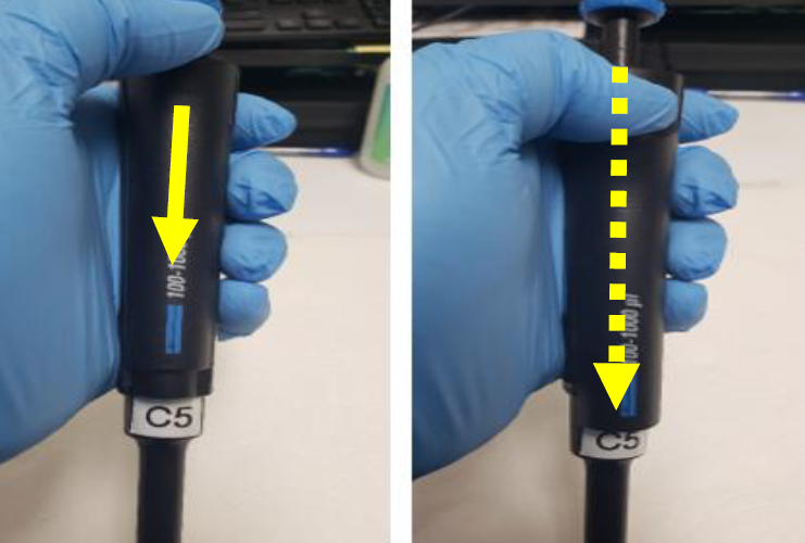
    Press and hold down the VWR EHP tip ejector button as you pull down and slide the tip ejector sleeve away from the pipette shaft. See Figure 1.0
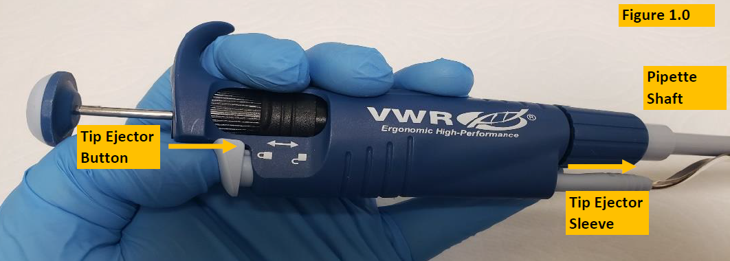
    Push down VWR EHP ejector button

    NOTE: Figure 1.1 shows the tip ejector sleeve removed from the pipette. See replacement parts for a complete list of tip ejector sleeves, if needed.
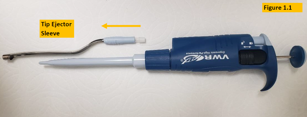
    Remove VWR EHP tip ejector
    Step 2:

    Unscrew the shaft coupling nut slowly and away from the pipette body. Figure 1.2


    NOTE: There is an internal spring that is under pressure and may pop open forcibly. Open slowly over a table in case internal parts pop out.
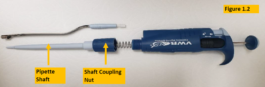
    Disassembly of VWR EHP lower part

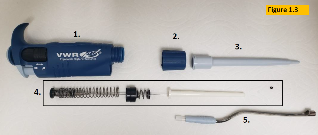
    NOTE: Once the shaft coupling nut is unthreaded and lower shaft assembly is separated from the body, the following parts are exposed for PM purposes:

    1. Pipette Body
    2. Shaft Coupling Nut
    3. Pipette Shaft
    4. Piston Assembly
    5. Tip Ejector Sleeve
      Figure 1.3
    Internal components of VWR EHP lower part
    Step 3:

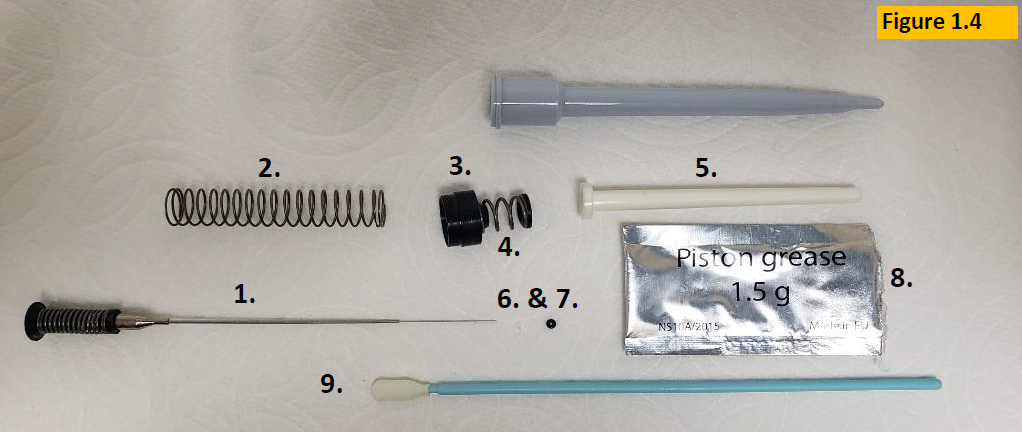
    Remove the following components from the VWR EHP piston assembly as in Figure 1.4:

    1. Piston
    2. Piston Spring
    3. Large Retainer
    4. Small Spring/Retainer
    5. Seal Spacing Tube
    6. Seal
    7. O-Ring
    Labeled parts of VWR EHP piston assembly
    Step 4:

    Clean and remove old lubricant/grease from piston with a Kim wipe. Figure 1.5. Take care to not scratch the piston. Turn/fold over the Kim wipe, so a fresh and unused portion comes in contact with the piston. See VWR EHP replacement parts for piston assemblies, if a replacement is needed. Look for rust, scratches, warped/bent, pit marks, visible chemical splash.
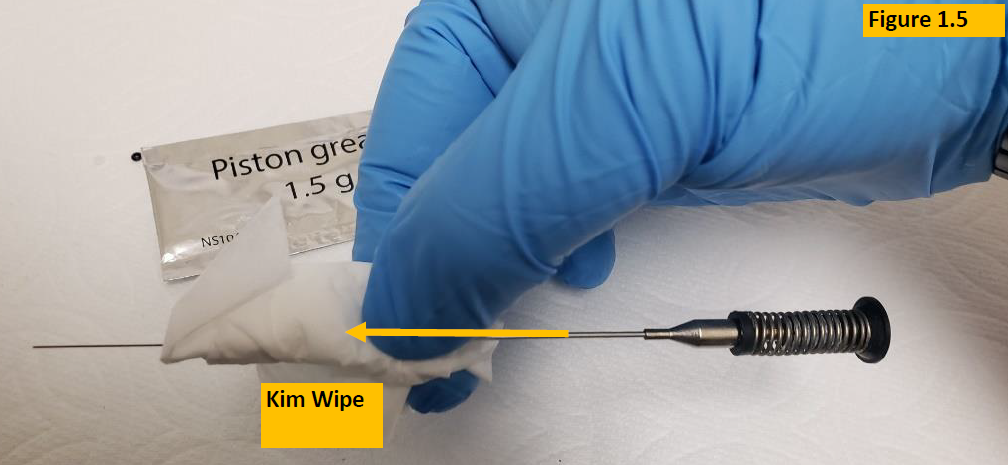
    Wipe piston with a Kim Wipe
    Step 5:

    With a clean foam swab apply a light, but slightly visible coating of the 1.5g piston grease onto the piston. Figure 1.6


    Note: Lubricating the piston from the piston tip to approximately 2/3 of the way up is more than sufficient. No need to lubricate the entire piston.
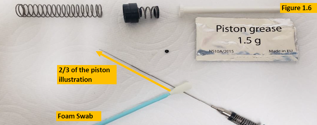
    Grease piston
    Step 6:

    Inspect and replace the seal and o-ring. It’s recommended to replace both at the same time to allow them to wear in together. See VWR EHP replacement parts for seal
    and o-ring part numbers. Look for cracks, wear and tear, chemical splash, shape, etc.
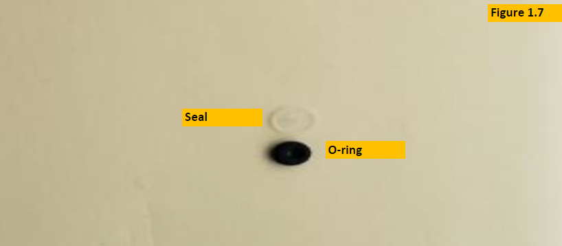
    Seal/o-ring
    Re-assembly Instructions:
    Step 7:

    Install the following parts in order as shown in Figure 1.8.

    1. Install piston spring (1) onto piston (6).
    2. Install large retainer (2) onto piston spring (1), then onto piston (6).
    3. Install seal spacing tube (3) onto retainers (2).
    4. Lastly install new seal and o-ring onto piston assembly. O-ring should be installed last.
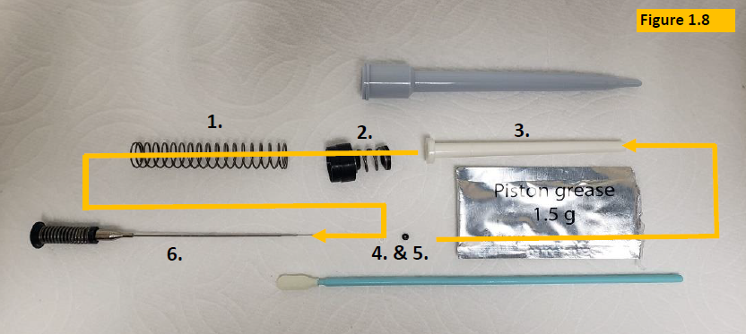
    The order of reassembly parts for VWR EHP piston assembly

    How Piston should look upon reassembly:

    Correct order of reassembly
    Step 8:

    Place piston assembly back into the pipette shaft. Then screw the shaft coupling nut back onto the pipette body until snug. Figure 1.9
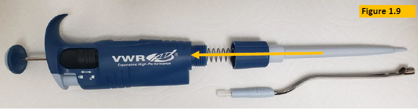
    Reattaching VWR EHP lower part
    Step 9:

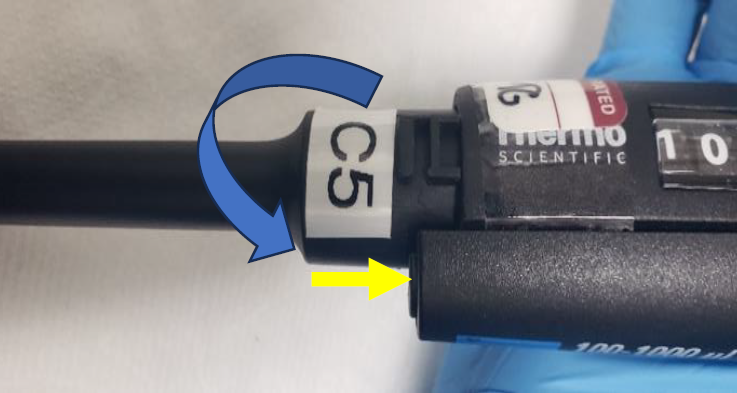
    Reattach tip ejector sleeve to pipette body. Figure 2.0
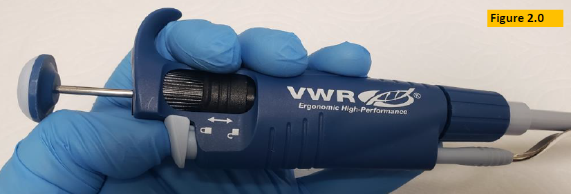
    Reattach ejector
    Step 10:

    Allow fully reassembled VWR EHP pipette to equilibrate at least 60 minutes before verifying accuracy and precision on a 4-5 place analytical balance.

    Related Posts:

    How to Calibrate a VWR Ergonomic High Performance (EHP) Pipette
    Preventive Maintenance: VWR Ultra High-Performance (UHP) Single Channel Pipette
    How to Calibrate a VWR Ultra High Performance (UHP) Single Channel Pipette

    Disclaimer: Any action you take using the information on this website is strictly at your own risk. The information herein does not constitute professional advice and is general in nature. We make no warranty that this information will meet your requirements, be safe, accurate, or error-free. Pipette Supplies, Inc. is not responsible for any errors or omissions, any results obtained from the use of this information, or any loss or damage arising out of the use of this information. This site is for educational purposes only.
    Fair Use: Copyright Disclaimer under section 107 of the Copyright Act of 1976, allows for “fair use” for purposes such as comments, criticism, teaching, scholarship, news reporting, and research.
    Fair use is permitted by copyright statute that might otherwise be infringing.
  • Finnpipette F1 and F2 Tip Ejector Sleeve Replacement

    warning

    The process of removing, replacing, and reinstalling the F1 tip ejector sleeve requires great care, a high attention to detail, patience, and steady hands. Please dedicate a good work area with good lighting and space where small parts can be located should they pop/fly out during disassembly. Pipette damage and lost parts may occur if attention to detail is not maintained. Please proceed at your own risk.

    Replacement Parts:

    Finnpipette F1 Single Channel
    Finnpipette F2 Single Channel

    Disassembly Process:
    Step 1:

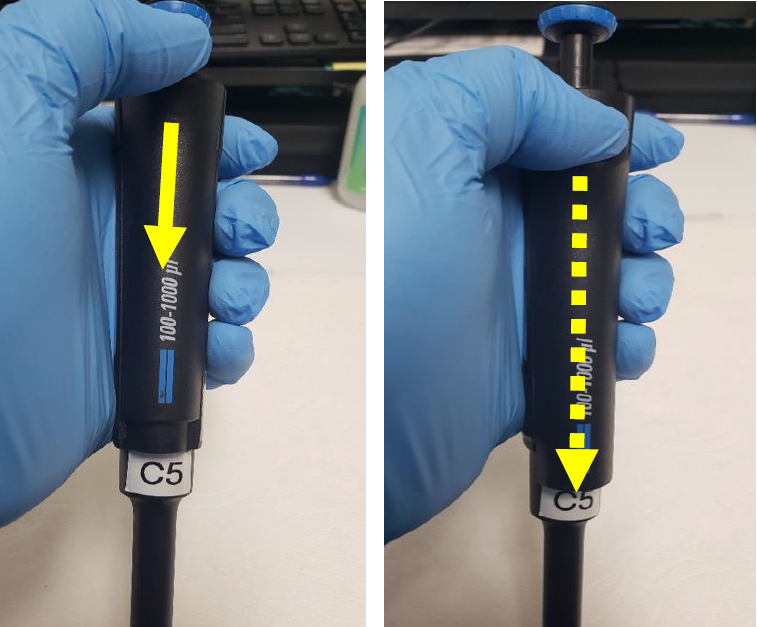
    Press down and hold the tip ejector button. This will lower the tip ejector sleeve for disassembly.

    NOTE:

    See ‘Replacement Parts’ above for F1 and F2 Tip Ejector Sleeve replacement parts, including ejectors.

    F1 tip ejector button depressed
    Step 2:

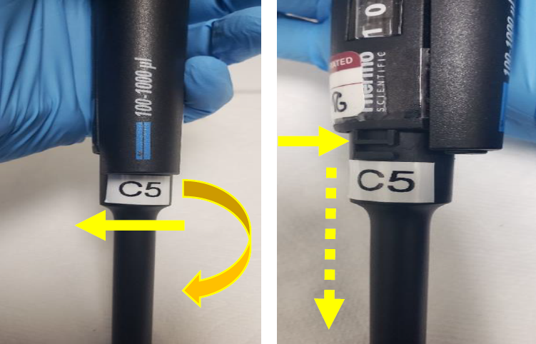
    Grasp the tip ejector sleeve and gently twist to the left to disengage it from the pipette body.

    Turn ejector to the left
    Step 3:

    Once disengaged slide it down and away from the shaft.

    Remove F1 tip ejector
    Reassembly Process
    Step 4:

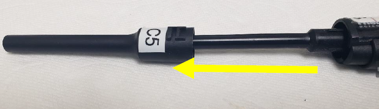
    Slide the new tip ejector sleeve up the shaft.

    Replace the tip ejector
    Step 5:

    Press down and hold the tip ejector button.

    Depress the ejector button
    Step 6:

    Twist the tip ejector sleeve gently to the right to engage it with the pipette body.

    Engage F1 tip ejector button by twisting to the right
    Related Posts:

    Finnpipette F1 and F2 Tip Ejector Mechanism Replacement
    Finnpipette Digital (Model 4500) Single Channel: How to Service and Replace the Tip Ejector Assembly
    Pipette Parts – Life Span, Life Cycle, and Performance
    Finnpipette Novus Error Codes

    Disclaimer: Any action you take using the information on this website is strictly at your own risk. The information herein does not constitute professional advice and is general in nature. We make no warranty that this information will meet your requirements, be safe, accurate, or error-free. Pipette Supplies, Inc. is not responsible for any errors or omissions, any results obtained from the use of this information, or any loss or damage arising out of the use of this information. This site is for educational purposes only.
    Fair Use: Copyright Disclaimer under section 107 of the Copyright Act of 1976, allows for “fair use” for purposes such as comments, criticism, teaching, scholarship, news reporting, and research.
    Fair use is permitted by copyright statute that might otherwise be infringing.
  • Which Instrument Should I Use?

    Instrument Use Cases

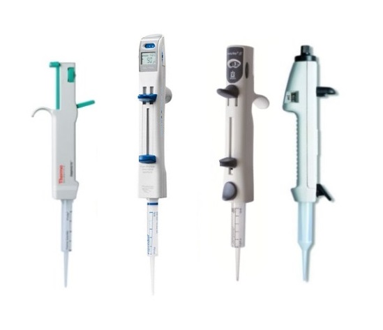
    Pipette:

    Pipettes are used to transfer small amounts of liquid, usually ranging from 0.1 µL and up to 10,000 µL.  They are the preferred measuring instrument in situations where accuracy and precision are essential. The pipette comes in single and multichannel options. The single channel mechanical pipette is known to be the workhorse in every life sciences laboratory worldwide.  You’ll typically find a set of them on every technician’s lab bench.

    pipettes
    Controllers:

    Pipette controllers are used with serological pipets for quickly and repetitively filling and releasing volumes of liquid. These devices offer ambidextrous capabilities and include different function modes and speed dials to adjust for different liquid volumes and viscosity. Controllers are the preferred instruments when repeatedly dispensing larger volumes (typically 1-100mL). The accuracy of the dispensed liquid is controlled by the manual manipulation of the dispense/aspirate controls.

    controllers
    Repeaters:

    Repeaters are used to repeatedly dispense the same volume of liquids multiple times without having to aspire in between. They are more accurate than controllers and are typically used for volume ranges between 1µL and 50mL.

    repeaters
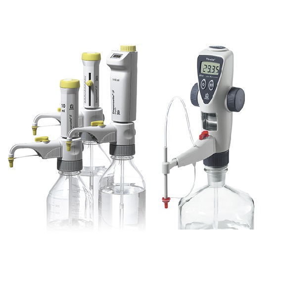
    Bottletop Dispensers / Burrettes:

    Bottletop dispensers are the best way to dispense aliquots of liquid from large glass or plastic bottles. The bottletop burette’s job is to provide reproducible dispensing without wasting reagents.

    Bottletop Dispensers / Burrettes
    Positive Displacement Pipettes:

    Positive displacement pipettes are the best tool for use with liquids that render traditional air-displacement pipettes ineffective. The piston directly expels the media from the tip, wiping the tip walls completely clean. This results in negligible residual wetting and highly accurate, reproducible results, especially with viscous, foaming, high-vapor-pressure, and other “problematic” liquids. They are excellent tools for applications in wastewater treatment plants, biochemical, genetics and molecular biology laboratories, wineries, breweries, refineries, and more.

    positive displacement pipettes
    Related Posts:

    How to Find Your Part Online
    Types of Pipette Tips
    Top 10 Crimes Committed Against Pipettes
    Pipette Parts – Life Span, Life Cycle, and Performance

    Disclaimer: Any action you take using the information on this website is strictly at your own risk. The information herein does not constitute professional advice and is general in nature. We make no warranty that this information will meet your requirements, be safe, accurate, or error-free. Pipette Supplies, Inc. is not responsible for any errors or omissions, any results obtained from the use of this information, or any loss or damage arising out of the use of this information. This site is for educational purposes only.
    Fair Use: Copyright Disclaimer under section 107 of the Copyright Act of 1976, allows for “fair use” for purposes such as comments, criticism, teaching, scholarship, news reporting, and research.
    Fair use is permitted by copyright statute that might otherwise be infringing.
  • How to Find Your Part Online

    Our website has multiple ways to find the part you need. The best search method will depend on what information you already have.

    If you have the part number:

    Enter the part number in the search bar.

    If you have the pipette model name:

    Search the ‘Replacement Parts’ tab for your pipette model. For example, if you are working with Rainin’s Pipet-Lite XLS Single Channel, you would search under the ‘P’ tile for ‘Pipet-Lite XLS’. From there, you will find all the available parts.

    If you have neither, but you know the manufacturer name:

    Use the ‘By Brand’ tab to search by pipette manufacturer. Click into the ‘Pipette Parts’ category and review the pipette model pictures to find yours. Click through the subsequent categories to find the part you need.

    If you are having trouble finding your part, contact us and we’ll be happy to help.

    Related Posts:
    Top 10 Crimes Committed Against Pipettes
    Types of Pipette Tips
    Pipette Parts – Life Span, Life Cycle, and Performance
    Non-Linear Volume Readings – When Should A Calibration Adjustment Be Made?

  • Gilson Microman / Microman E and RAININ Pos-D: Calibration Instructions

    Warning. Proceed at your own risk.

    The process of performing a Microman / Microman E / Pos-D calibration adjustment should always be the last option. Verifying that all other components are in good working condition and part replacement, as needed, should be done first. Pipette damage and lost parts may occur if attention to detail is not maintained. Please proceed at your own risk.

    Required Microman Calibration Adjustment Tool:
    Locking Cap Lever Tool – GI F148172

    NOTE: For illustration purposes, these instructions focus on the Gilson Microman. The instructions below and the locking cap lever tool can also be used with the Gilson Micronman E and Rainin Pos-D.

    Printable Calibration Log
    Printable Calibration Stickers (for use with Avery 5960 labels)

    Microman Calibration Instructions
    Step 1:

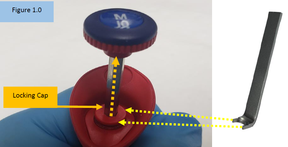
    Insert the open end of the Locking Cap Lever Tool into the Microman locking cap. Figure 1.0.
    Once inserted into the locking cap, pry the locking cap upward.

    Insert tool into locking cap
    Step 2:

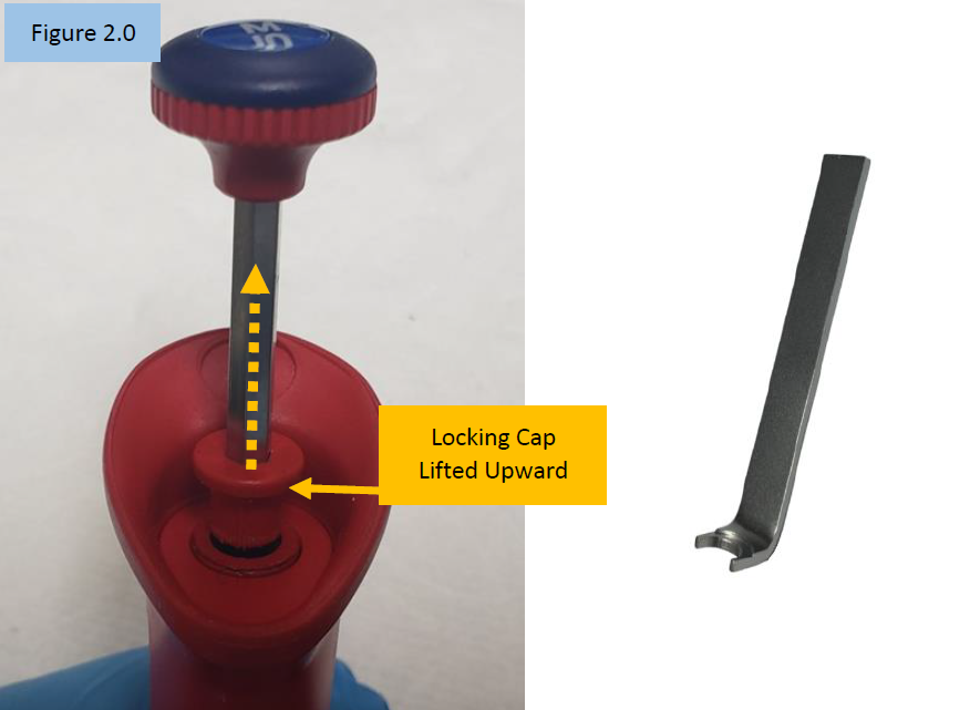
    Notice the locking cap is now lifted upward and out of the pipette body.


    CAUTION: With the locking cap now lifted upward, any movement of the adjustment knob will affect the calibration.

    Lift locking cap upward
    Step 3:

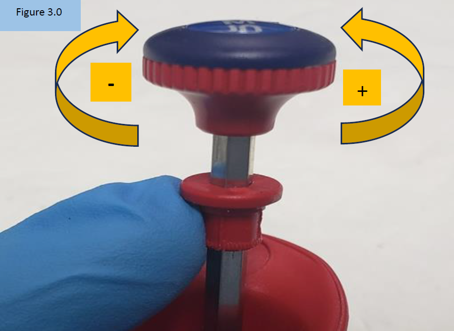
    Rotate the adjustment knob:

    A. Counter-clockwise to increase the volume aspirated and dispensed ( + )
    B. Clock-wide to decrease the volume aspirated and dispensed ( – ), Figure 3.0

    NOTE: Only turn the adjustment knob 1/8th of a turn at a time. Large turns will grossly affect desired results. For best results, it’s recommended to make adjustments at the 10% volume.

    Microman calibration adjustment knob turning
    Step 4:

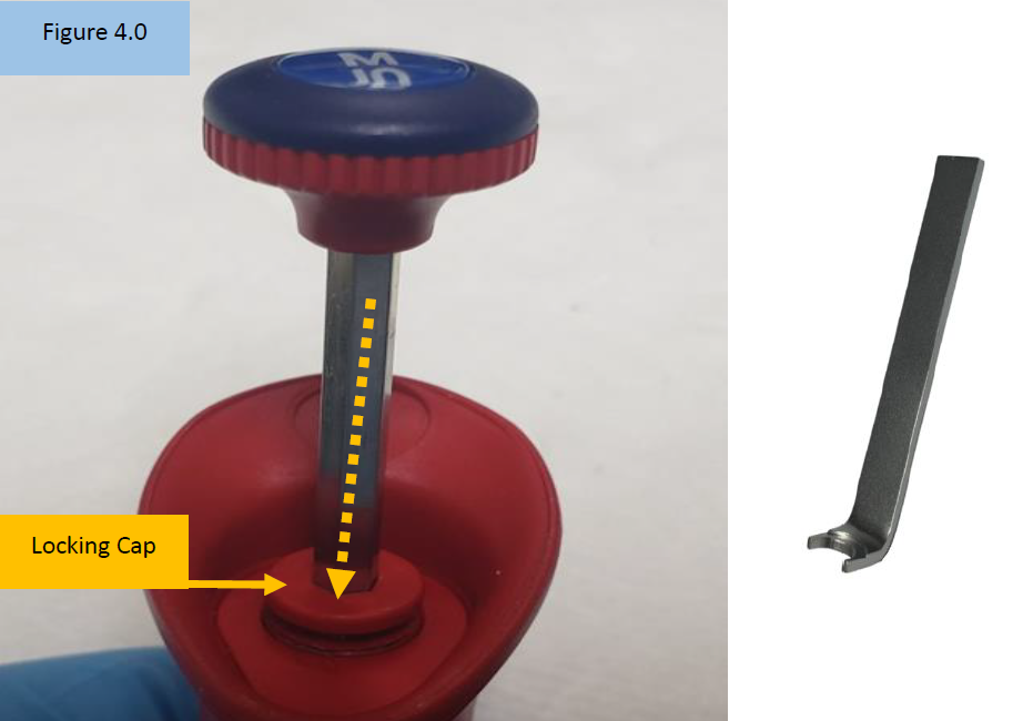
    Insert the open end of the Locking Cap Lever Tool into the Microman locking cap. Push it back down into the body opening until it clicks back into place. Ensure it is fully in place. Figure 4.0.

    Microman calibration - adjustment knob Locking cap seated
    Step 5:

    Check the calibration adjustment made on a 4-5 place analytical balance. Repeat steps 1-5 if additional calibration adjustment is needed.

    Related Posts:
    Gilson Microman Inspection, Spring/Clamp Replacement, and Preventive Maintenance
    Gilson Pipette Legend
    Rainin Pipette Legend

    Disclaimer: Any action you take using the information on this website is strictly at your own risk. The information herein does not constitute professional advice and is general in nature. We make no warranty that this information will meet your requirements, be safe, accurate, or error-free. Pipette Supplies, Inc. is not responsible for any errors or omissions, any results obtained from the use of this information, or any loss or damage arising out of the use of this information. This site is for educational purposes only.
    Fair Use: Copyright Disclaimer under section 107 of the Copyright Act of 1976, allows for “fair use” for purposes such as comments, criticism, teaching, scholarship, news reporting, and research.
    Fair use is permitted by copyright statute that might otherwise be infringing.
  • Gilson Microman Inspection, Spring/Clamp Replacement, and Preventive Maintenance

    Warning

    The process of inspecting, performing preventive maintenance, and replacing/reinstalling parts on the Gilson Microman requires great care. A high attention to detail, patience, and steady hands are required. Please dedicate a good work area with good lighting and space where small parts can be located should they pop/fly out during disassembly. Pipette damage, affected calibration, and lost parts may occur if attention to detail is not maintained. Please proceed at your own risk.

    To review before Gilson Microman disassembly:

    These instructions are compatible with the Gilson Microman, not the Microman E.

    Microman Replacement parts, including the parts listed in this post, can be found here.

    External pipette and parts familiarity (Figure 1.0):

    Gilson Microman external parts

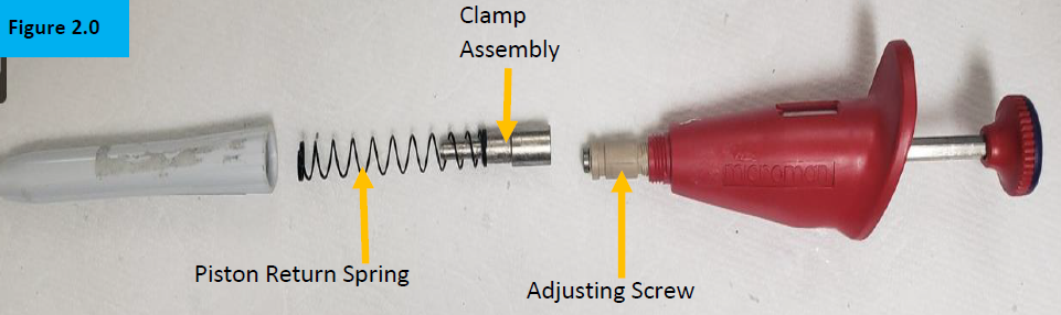
    Internal pipette and parts familiarity (Figure 2.0):

    Gilson Microman internal parts

    Disassembly Process

    Step 1:

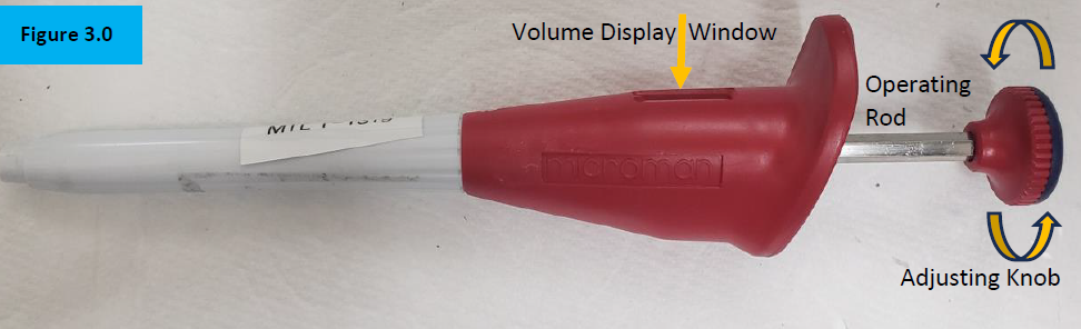
    Wind the adjusting knob so that the nominal volume (100%) is displayed in the volume window. Figure 3.0.


    NOTE: This will ensure the internal adjusting screw is mostly protected inside of the pipette body prior to disassembly and preventive maintenance.

    Wind operating rod
    Step 2:

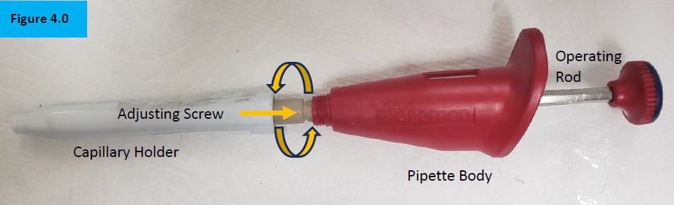
    Unscrew the white colored capillary holder from the pipette body. Figure 4.0.

    NOTE: Notice the tan/beige colored adjusting screw. This will be mostly visible if the volume is not adjusted to nominal prior to disassembly of the shaft. Take great care not to rotate or turn this component or calibration could be affected.

    Remove capillary holder
    Step 3:

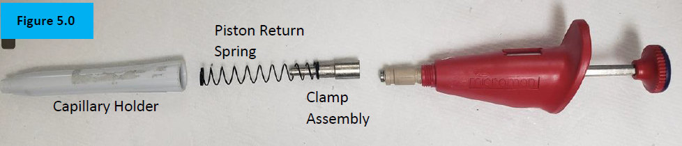
    Separate the white capillary holder from the pipette body to expose the internal piston return spring and clamp assembly. Figure 5.0.

    Disassembled Gilson Microman
    Step 4:

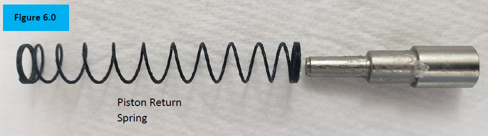
    Inspect the piston return spring for cracks, rust, breaks. Replace as needed. Figure 6.0.

    Piston return spring

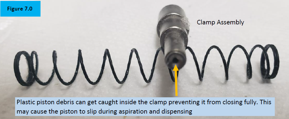
    Inspect the clamp assembly for rust, chemical splash, and/or plastic piston debris that could be caught inside the clamp teeth. Figure 7.0.

    Clamp assembly

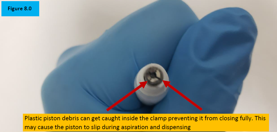
    Inspect inside the clamp assembly for plastic shavings or debris that can prevent the clamp assembly from opening and closing fully. Replace as needed. Figure 8.0.

    possible piston debris

    Reassembly Process

    Step5:

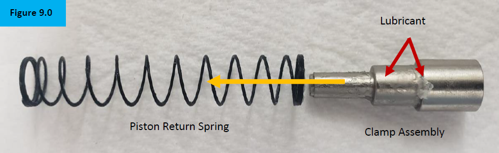
    Insert the clamp assembly into the piston return spring. Figure 9.0.

    NOTE: If desired, a small amount of lubricant can be applied to the outside of the clamp assembly to help provide a quieter piston return spring during aspiration and dispensing.

    lubricant on piston assembly
    Step 6:

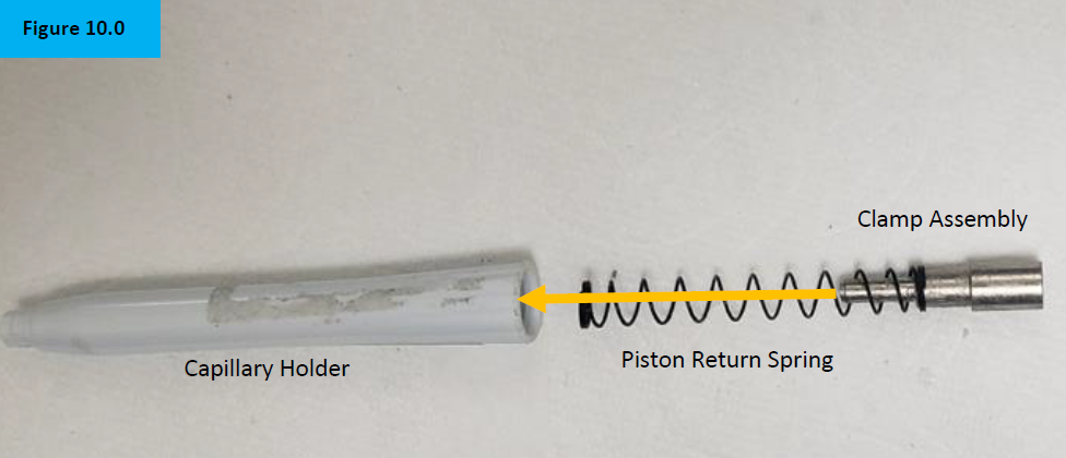
    Slide the piston return spring and clamp assembly inside the capillary holder. Figure 10.0.

    lower part assmebly
    Step 7:

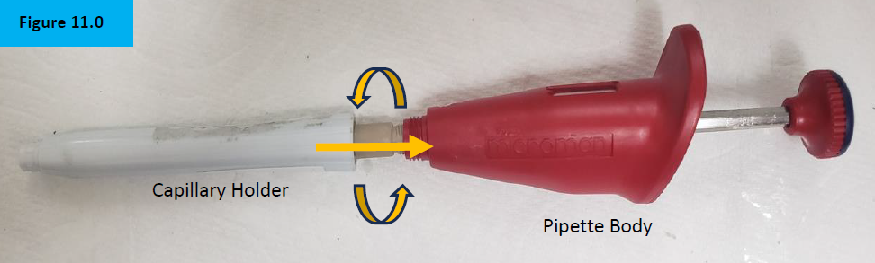
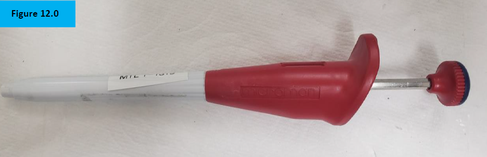
    Screw on and attach the capillary holder to the pipette body. Figure 11.0.

    Gilson Microman reassembly
    reassembled Gilson Microman
    Step 8:

    Check for functionality, accuracy, and precision with Di Water and an appropriate analytical balance. Recheck work as necessary.

    testing process

    Related Posts:
    Gilson Pipette Legend
    General Troubleshooting – Liquid Leak Test Testing & 12 Point Pipette Inspection
    Top 10 Crimes Committed Against Pipettes
    Pipette Parts – Life Span, Life Cycle, and Performance

    Disclaimer: Any action you take using the information on this website is strictly at your own risk. The information herein does not constitute professional advice and is general in nature. We make no warranty that this information will meet your requirements, be safe, accurate, or error-free. Pipette Supplies, Inc. is not responsible for any errors or omissions, any results obtained from the use of this information, or any loss or damage arising out of the use of this information. This site is for educational purposes only.
    Fair Use: Copyright Disclaimer under section 107 of the Copyright Act of 1976, allows for “fair use” for purposes such as comments, criticism, teaching, scholarship, news reporting, and research.
    Fair use is permitted by copyright statute that might otherwise be infringing.
  • Eppendorf Research Plus Sealing Ring Replacement – 1000uL

    Warning

    The process of removing, replacing, and reinstalling the Research Plus sealing ring requires great care, a high attention to detail, patience, and steady hands. Please dedicate a good work area with good lighting and space where small parts can be located should they fly out during disassembly. Pipette damage and lost parts may occur if attention to detail is not maintained. Please proceed at your own risk.

    Recommended Parts and Items
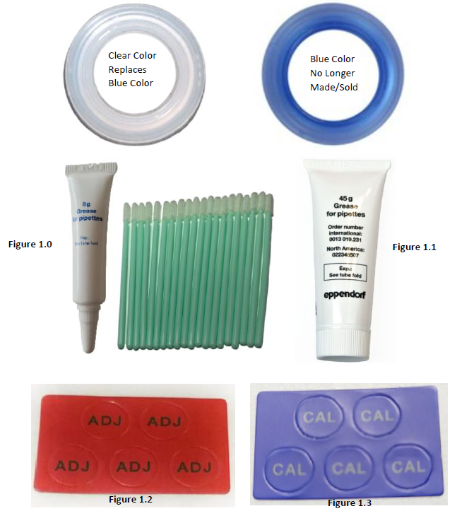
    recommended Research plus parts and tools (incl sealing ring, grease, stickers)

    Disassembly Process for Sealing Ring Replacement:

    Step 1:

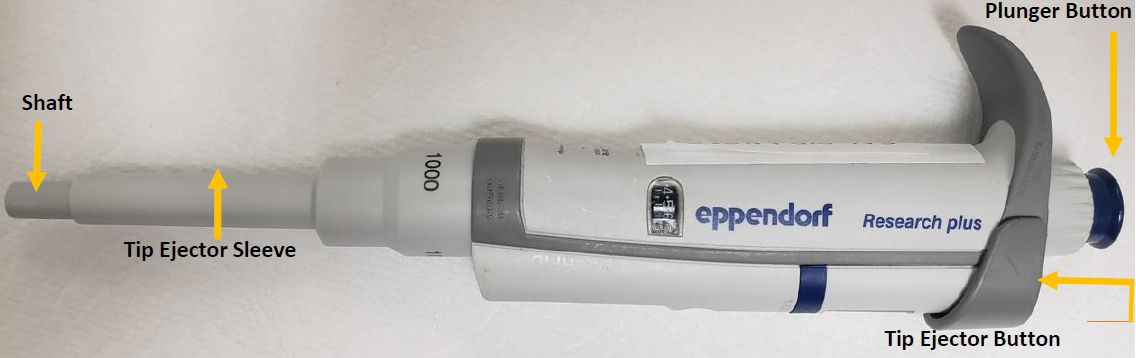
    Identify and make yourself familiar with the main components that will need to be used to gain access to the internal sealing ring.

    Eppendorf Research Plus external parts labeled
    Step 2:

    Press down and hold the tip ejector button to lower the tip ejector sleeve. Figure 2.0.

    Fig 2.0, remove ejector sleeve
    Step 3:

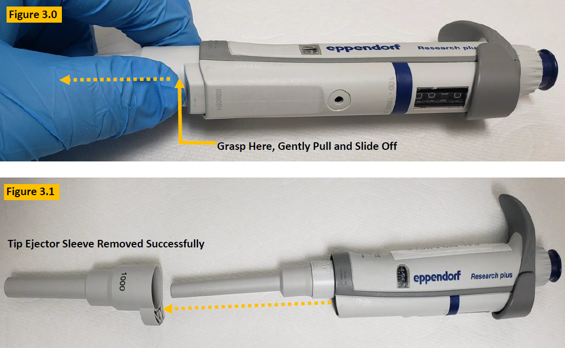
    With the tip ejector button pressed, gently grasp the tip ejector sleeve, and gently slide and pull it off from the
    pipette body. Lay aside for reassembly. Figure 3.0.

    disassembly and removal of ejector sleeve

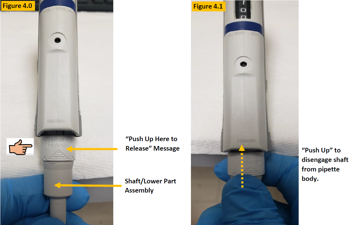
    LOOK: Notice the engraved words on the shaft (lower part) “Push Up Here to Release” as shown in Figures 4.0 and 4. 1.


    Step 4:

    Push up gently but firmly to disengage the lower part assembly (shaft) from the pipette body. See Figure 4.1.

    Fig 4.0-4.1, disengage shaft from pipette body

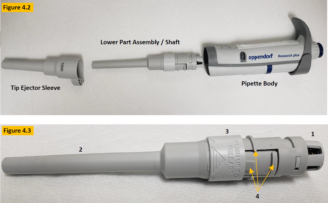
    COMMENT: Figure 4.3 is an up close picture of the lower part assembly (Shaft). Familiarize yourself with the component names:

    1. Piston Cap
    2. Shaft
    3. Push up/release.
    4. Locking tabs/rings
    Fig 4.2-4.3, disassembled pipette lower part

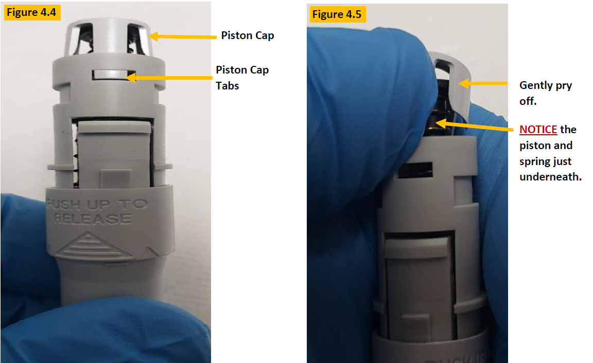
    CAUTION: The piston cap holds the piston and piston spring in place, under tension. Use caution when removing the piston cap to prevent the spring and piston from flying out. Notice the piston cap tabs that hold it in place as shown in Figure 4.4.


    Step 5:

    Gently pry off the piston cap, as shown in Figure 4.5. Use your thumb to keep tension on the cap until you can grasp the piston and spring that are just below the piston cap. Remove the piston assembly from the shaft.

    Fig 4.4-4.5,  removing the piston cap

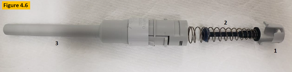
    COMMENT: Observe the contents of the lower part after disassembly:

    1. Piston Cap
    2. Piston Assembly with spring & sealing ring
    3. Shaft/Lower Part
    Fig 4.6, removed piston and spring
    Step 6:

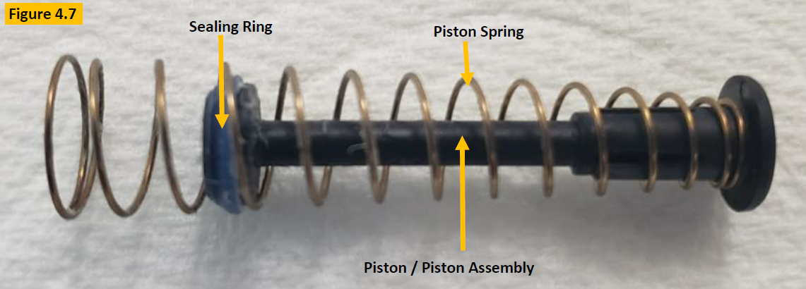
    Inspect the piston, spring, sealing ring, and lubricant for damage, chemical splash, etc. as in Figure 4.7. Clean any component with a lint-free cloth (i.e. kim wipe) and 70% IPA as needed, and or replace if necessary.

    Fig 4.7, Research Plus sealing ring, piston, and spring
    Step 7:

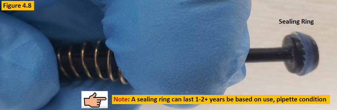
    To clean the sealing ring and remove old lubricant, collapse the piston spring (Figure 4.8) so the sealing ring is unobstructed. Clean the sealing ring with 70% IPA and lint-free cloth. Inspect the sealing ring for cracks, splits, or wear. Replace as needed.

    Fig 4.8, Research plus sealing ring on piston
    Step 8:

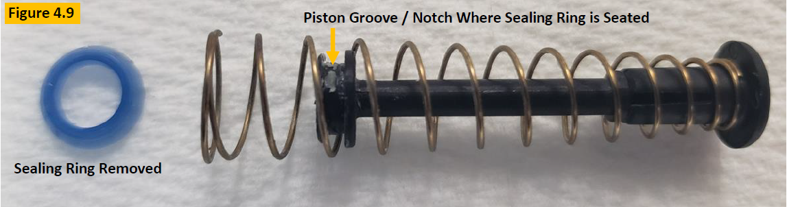
    To replace the sealing ring, follow step 7 above, including cleaning removing the sealing ring from the piston with a
    small-bladed tool. See Figure 4.9.

    Fig 4.9, Research Plus sealing ring removed, piston groove
    Step 9:

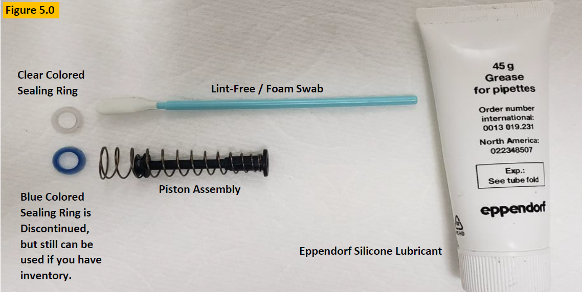
    Ensure the piston, piston spring, and piston groove are clean and free of lubricant.


    COMMENT: Per Figure 5.0, prepare your Eppendorf silicone grease, lint-free / foam swab, and Research Plus sealing ring for lubrication and installation.

    Fig 5.0, Eppendorf silicone grease, lint-free / foam swab, and Research Plus sealing ring
    Step 10:

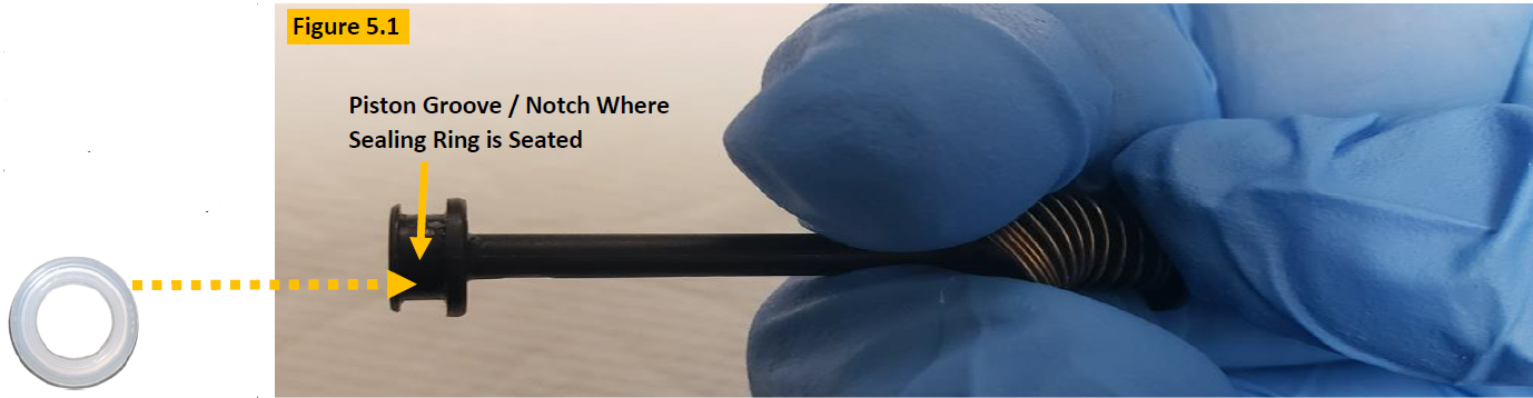
    Collapse the piston spring as shown in Figure 5.1, to install the new sealing ring into the piston grooved / notched
    position until seated fully.

    Fig 5.1, piston groove/notch where sealing ring is seated
    Step 11:

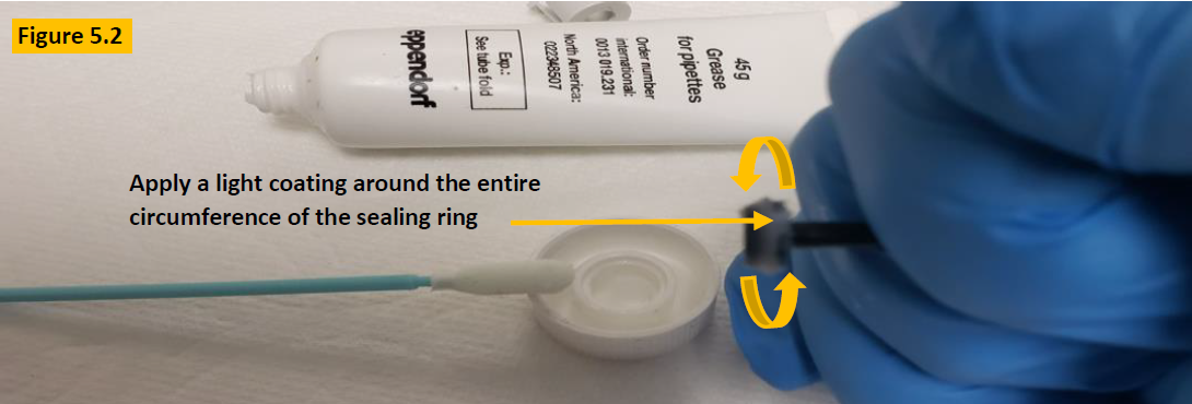
    With the new sealing ring installed, apply a light coating (slightly visible to the eye) of Eppendorf silicone lubricant around the entire circumference of the sealing ring as shown in figure 5.2.

    Fig 5.2, light coating of lubricant on sealing ring
    Step 12:

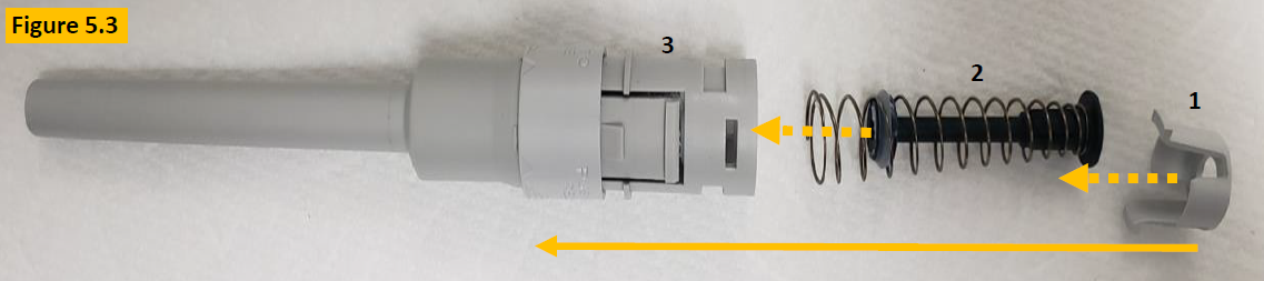
    After installation and lubrication of the sealing ring, prep the lower part for reassembly as shown in Figure 5.3.

    Fig 5.3, disassembled lower part
    Step 13:

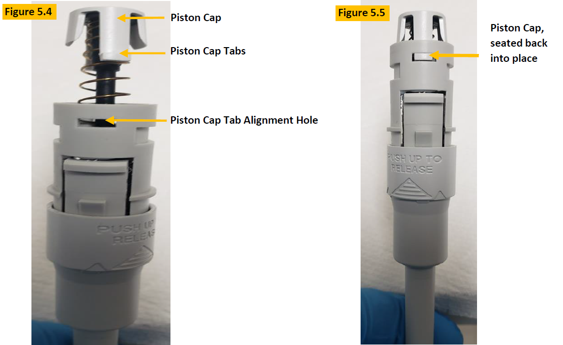
    After placing the piston assembly back inside the shaft/lower part, place the piston cap over the end of the piston and
    press down until the tabs align and click in place (Figure 5.5).

    Fig 5.4-5.5, reinstalling piston cap
    Step 14:

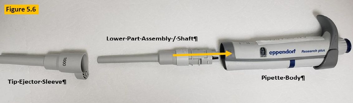
    Insert the lower part assembly / shaft back into the pipette body opening and is fully attached. Figure 5.6.

    Fig 5.6, reinstalling lower part
    Step 15:

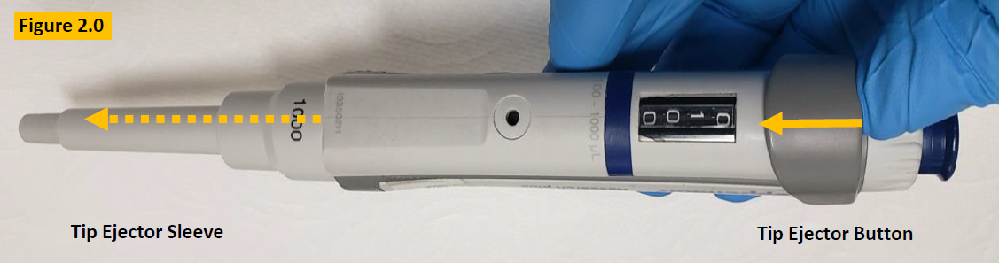
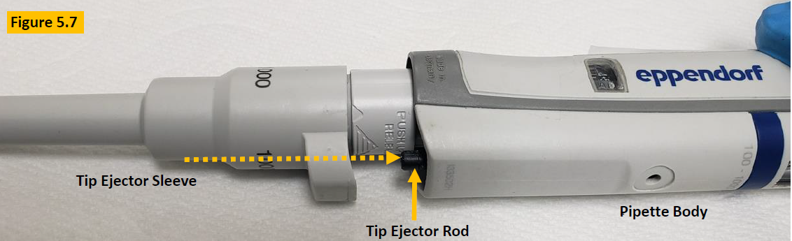
    Press and hold the tip ejector button down. The black colored ejector rod will protrude from the body. Align the ejector sleeve with the ejector rod and click the tip ejector sleeve back onto the pipette. Figure 5.7.

    Fig 5.7, reinstalling ejector
    Step 16:

    Once the pipette is reassembled, allow it to equilibrate to ambient conditions for at least 60 minutes.


    Step 17:

    Perform a liquid leak test at nominal volume and then confirm pipette accuracy and precision, and desired results are obtained.

    Adjustment Process – Only If Needed

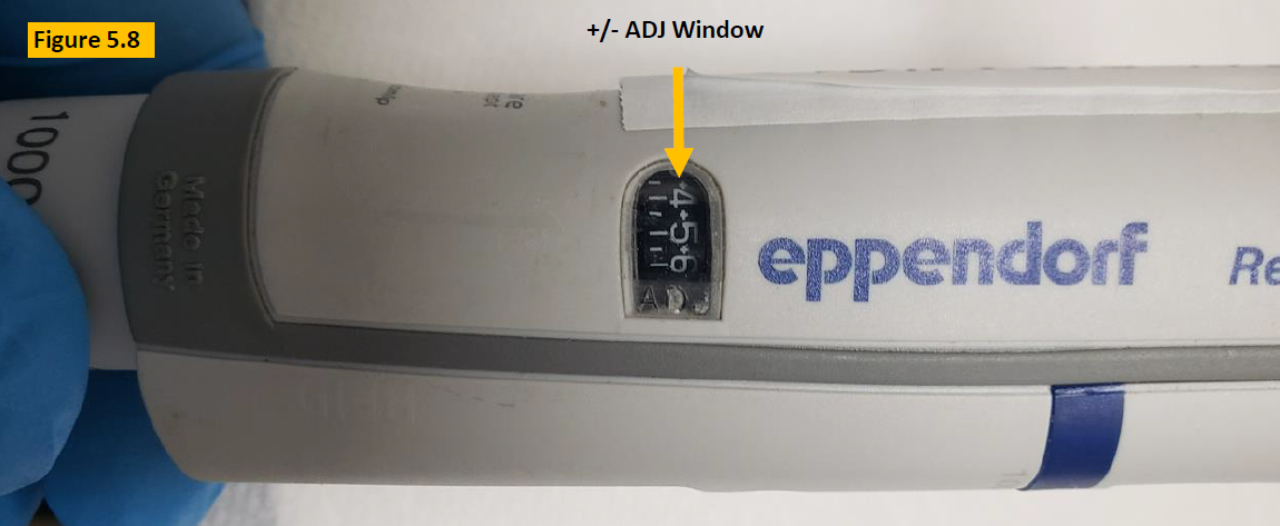
    COMMENT: Figure 5.8, If the volume that is aspirated and dispensed is not desirable, then recheck your work as well
    as consider…

    1. Is the ADJ window digits at “0”?
    2. A possible calibration adjustment
    Fig 5.8, adjustment window
    Step 18:

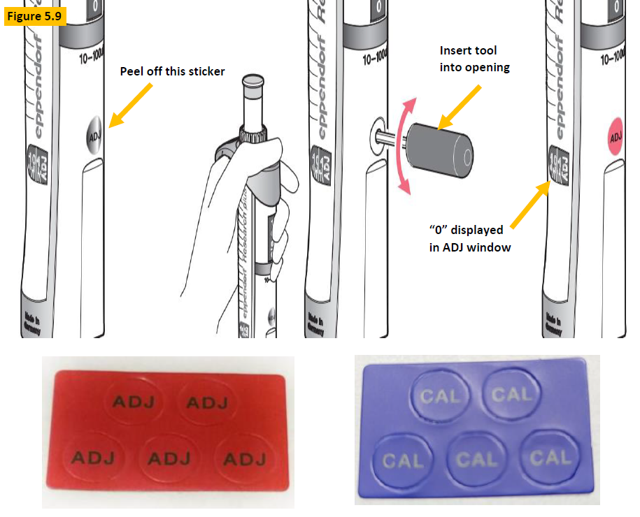
    Figure 5.9. Peel off the red, blue, or gray colored ADJ or CAL sticker that covers the adjustment hole.


    Step 19:

    Press down and hold the tip ejector button, then insert the adjustment tool (EP 3120633006) into the opening and rotate until ADJ window aligns the “0” with the carat symbol.

    Step 20:

    With ADJ window set to “0”, recheck to see if desired volume is now achieved.


    Step 21:

    Affix replacement CAL or ADJ sticker over opening after tool is removed.


    NOTE: If desired volume is not achieved, proceed to step 22.

    Fig 5.9, adjustment visual

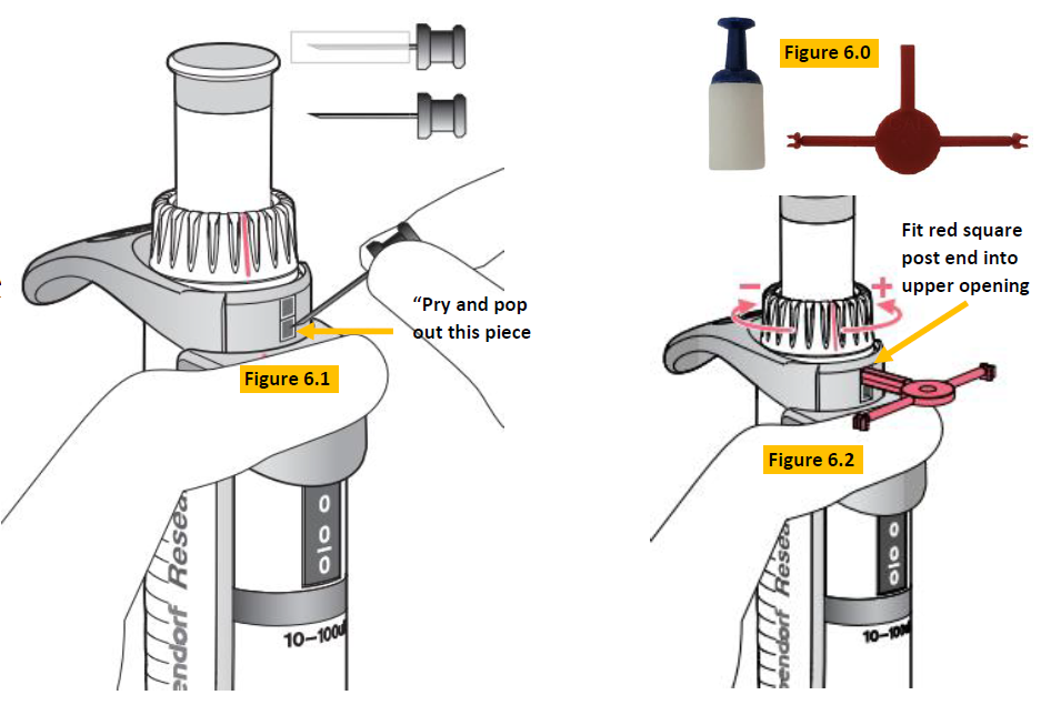
    Locate: Part number EP 3120639004/1, calibration adjustment tool as shown in Figure 6.0.


    Step 22:

    Press down and hold the tip ejector button. Insert the safety pin into the bottom square and pry/pop it out (Figure 6.1).


    Step 23:

    Insert the square post end of the red colored tool into the top gray square and push it downward so the red colored square post fits into the open slot (Figure 6.2). Adjust counter-clockwise to increase volume. Adjust clockwise to decrease volume.

    Fig 6.0-6.2, inserting safety plug
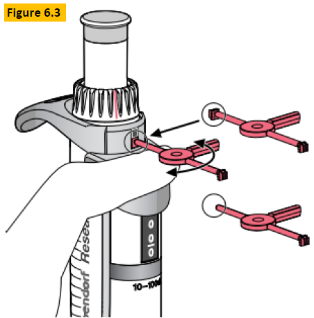
    Step 24:

    Once adjustment is completed, insert the replacement tab portion into the bottom opening and twist off until the tab
    is locked into position (Figure 6.3).

    Step 25:

    Check the pipette performance on a gravimetric balance to confirm desired results are obtained.

    Fig 6.3, inserting safety plug

    Related Posts:
    How to Calibrate an Eppendorf Research Plus Fixed Pipette
    Eppendorf Reference 2: How to Replace the Volume Catch (and Access the Counter Assembly)
    Eppendorf Xplorer Battery Replacement Instructions
    Top 10 Crimes Committed Against Pipettes

    Disclaimer: Any action you take using the information on this website is strictly at your own risk. The information herein does not constitute professional advice and is general in nature. We make no warranty that this information will meet your requirements, be safe, accurate, or error-free. Pipette Supplies, Inc. is not responsible for any errors or omissions, any results obtained from the use of this information, or any loss or damage arising out of the use of this information. This site is for educational purposes only.
    Fair Use: Copyright Disclaimer under section 107 of the Copyright Act of 1976, allows for “fair use” for purposes such as comments, criticism, teaching, scholarship, news reporting, and research.
    Fair use is permitted by copyright statute that might otherwise be infringing.
  • BrandTech Transferpette S Parts Decoded

    There have been many versions of the BrandTech Transferpette S over the years. Use this page to find the right parts for your pipette!

    Shop Spare Parts Here:
    Transferpette S Single Channel
    Transferpette S Multichannel

    To determine the year your pipette was manufactured, see BrandTech Serial Number Format.

    Transferpette S Single Channel (pre-2020)
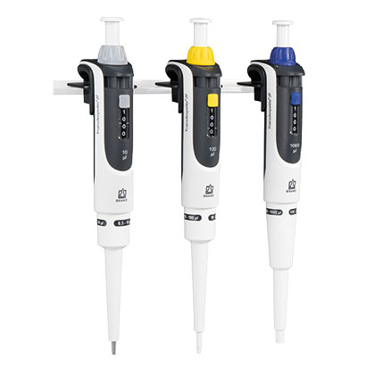
    Pre 2020 single channel

    NOTE: If the pipette still has an original GLASS piston (older units), it must be replaced with a new composite piston and seal. Check with Pipette Supplies for the correct part number.

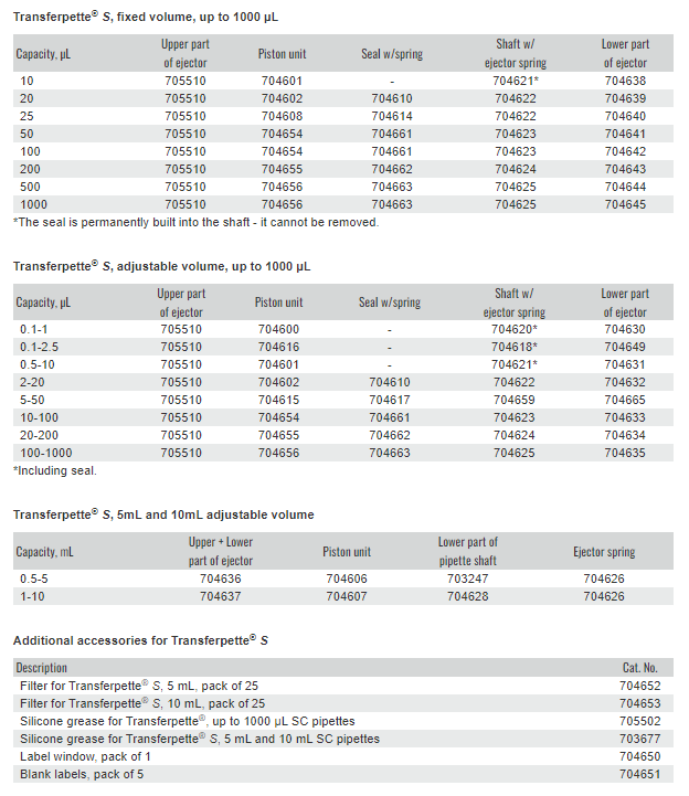
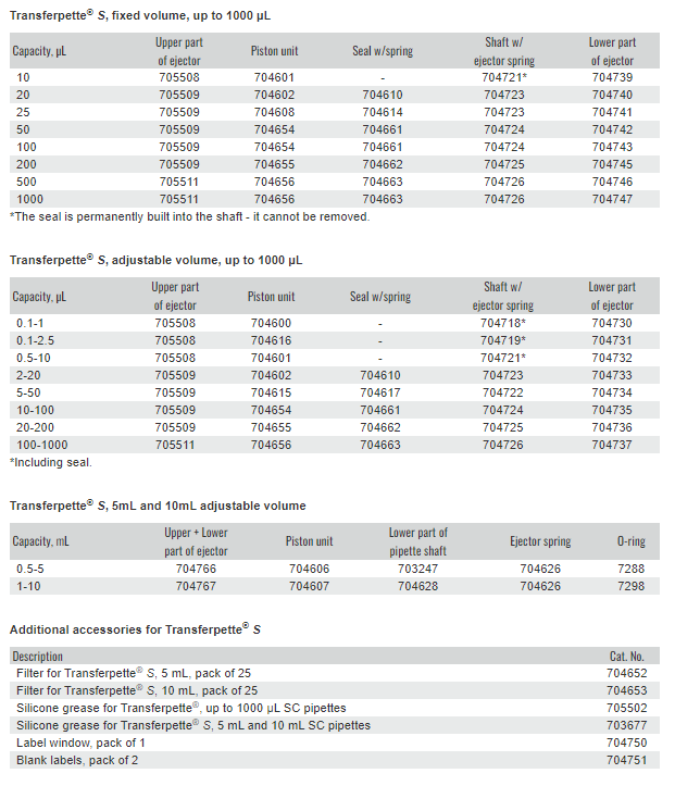
    BrandTech Transferpette S Single Channel (pre-2020) Spare Parts
    Transferpette S Single Channel (2020+)
    Post 2020 single channel

    NOTE: The pistons and seals did not change from the pre-2020 model. It is primarily the visible (outer shaft) components that are different.

    BrandTech Transferpette S Single Channel (post-2020) Spare Parts
    2026 Update for Transferpette S 2mL Fixed Pipette:
    Table displaying BrandTech Transferpette S Parts updates, detailing part number, description, volume range, and notes on serial number fixes for TFP S 2 mL parts.
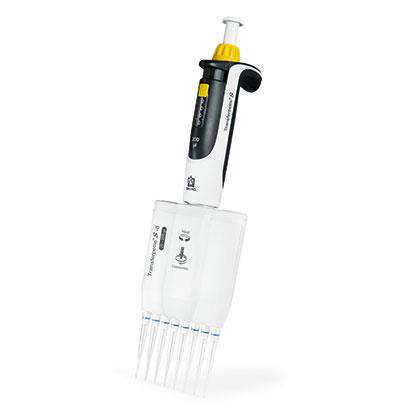
    Transferpette S Multichannel (pre-2020)
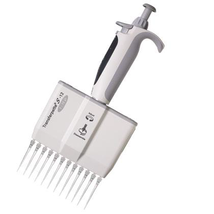
    Multichannel (pre-2020)
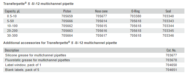
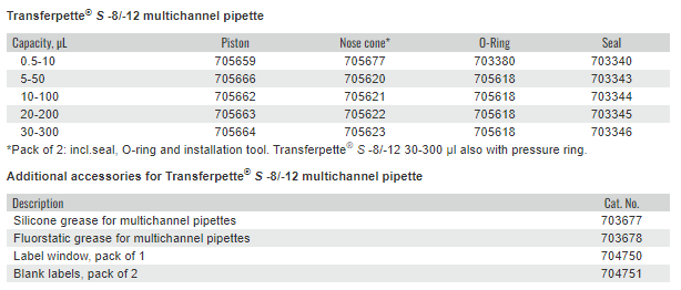
    BrandTech Transferpette S Multichannel (pre-2020) Spare Parts

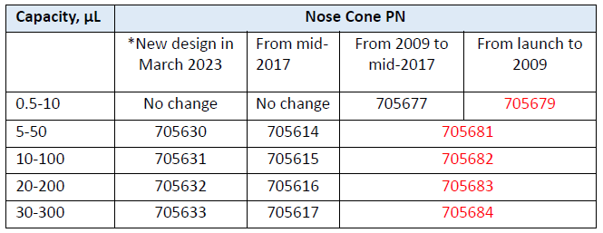
    Evolution of nose cone part numbers:

    BrandTech Transferpette S Multichannel (pre-2020) Nose Cones

    RED FONT = Discontinued; If pipette has not been updated with new nose cones, ALL nose cones must be replaced.

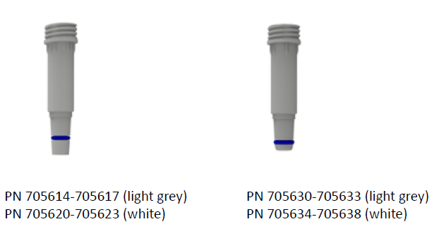
    *New nose cone design introduced in March 2023 is an alternative to 705614-705617 (see next section for pictures that illustrate the difference). Both options are available (until further notice) and compatible with the pipettes, BUT must have ALL nose cones of the same part number – cannot mix.

    Transferpette S Multichannel (2020+)
    Multichannel (post-2020)
    BrandTech Transferpette S Multichannel (post-2020) Spare Parts

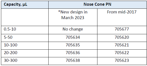
    NOTE: As of March 2023 (SN 23Cxxxxx), 5-50 μL to 30-300 μL BrandTech Transferpette S pipettes are manufactured with the newest design nose cone (see below); O-ring (705618) did NOT change


    Pipettes can use EITHER new or old design, but must have ALL of one design – cannot mix

    BrandTech Transferpette S Multichannel (post-2020) nose cones
    Illustration of old vs. new (from March 2023) nose cone design
    Illustration of old vs. new (from March 2023) nose cone design

    Light grey = pre-2020 model
    White = 2020+ model
    New design is more rounded and slightly shorter. Position of O-ring is modified.
    Materials and O-ring (705618) did NOT change.

    Related Posts:

    BrandTech Serial Number Format
    BrandTech Transferpette Nose Cone Part Numbers
    Transferpette Adjustment Knob Installation, Item # BT 9481

    Disclaimer: Any action you take using the information on this website is strictly at your own risk. The information herein does not constitute professional advice and is general in nature. We make no warranty that this information will meet your requirements, be safe, accurate, or error-free. Pipette Supplies, Inc. is not responsible for any errors or omissions, any results obtained from the use of this information, or any loss or damage arising out of the use of this information. This site is for educational purposes only.
    Fair Use: Copyright Disclaimer under section 107 of the Copyright Act of 1976, allows for “fair use” for purposes such as comments, criticism, teaching, scholarship, news reporting, and research.
    Fair use is permitted by copyright statute that might otherwise be infringing.
  • BrandTech Transferpette Multichannel Nose Cone Part Numbers

    The old BrandTech Transferpette (Mechanical) pipette was discontinued in 2015. Most replacement parts, including nose cones, are no longer available. You can find all available parts here: Transferpette Multichannel Mechanical

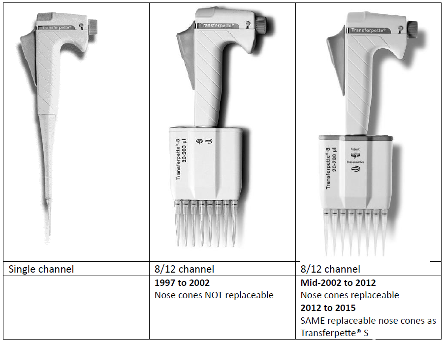
    Transferpette Eras

    Multichannel Transferpettes with serial numbers – 01K (Jan 2012) or newer can use nose cones for Transferpette S:

    Transferpette Nose Cone part numbers

    **Note that unless the pipette has already been updated with the nose cones above, ALL nose cones must be changed out to the current style; for most pipettes, it usually makes more sense to update to a new multichannel Transferpette S.

    Related Posts:

    Transferpette Adjustment Knob Installation, Item # BT 9481
    BrandTech Serial Number Format
    BrandTech Transferpette S Parts Decoded

    Disclaimer: Any action you take using the information on this website is strictly at your own risk. The information herein does not constitute professional advice and is general in nature. We make no warranty that this information will meet your requirements, be safe, accurate, or error-free. Pipette Supplies, Inc. is not responsible for any errors or omissions, any results obtained from the use of this information, or any loss or damage arising out of the use of this information. This site is for educational purposes only.
    Fair Use: Copyright Disclaimer under section 107 of the Copyright Act of 1976, allows for “fair use” for purposes such as comments, criticism, teaching, scholarship, news reporting, and research.
    Fair use is permitted by copyright statute that might otherwise be infringing.
  • BrandTech Serial Number Format

    If your pipette was manufactured prior to mid-November 2015:

    First two digits are the MONTH of manufacture (i.e., 01-12)
    Letter indicates YEAR of manufacture as shown below:
    BrandTech Serial Number Example: 01A1234

    A = 2003
    B = 2004
    C = 2005
    D = 2006
    E = 2007
    F = 2008
    G = 2009
    H = 2010
    J = 2011
    K = 2012
    L = 2013
    M = 2014
    N = 2015

    If your pipette was manufactured after mid-November 2015:

    First two digits are the YEAR of manufacture
    Letter indicates MONTH of manufacture as shown below:
    BrandTech Serial Number Example: 15L1234


    A = January
    B = February
    C = March
    D = April
    E = May
    F = June
    G = July
    H = August
    J = September
    K = October
    L = November
    M = December

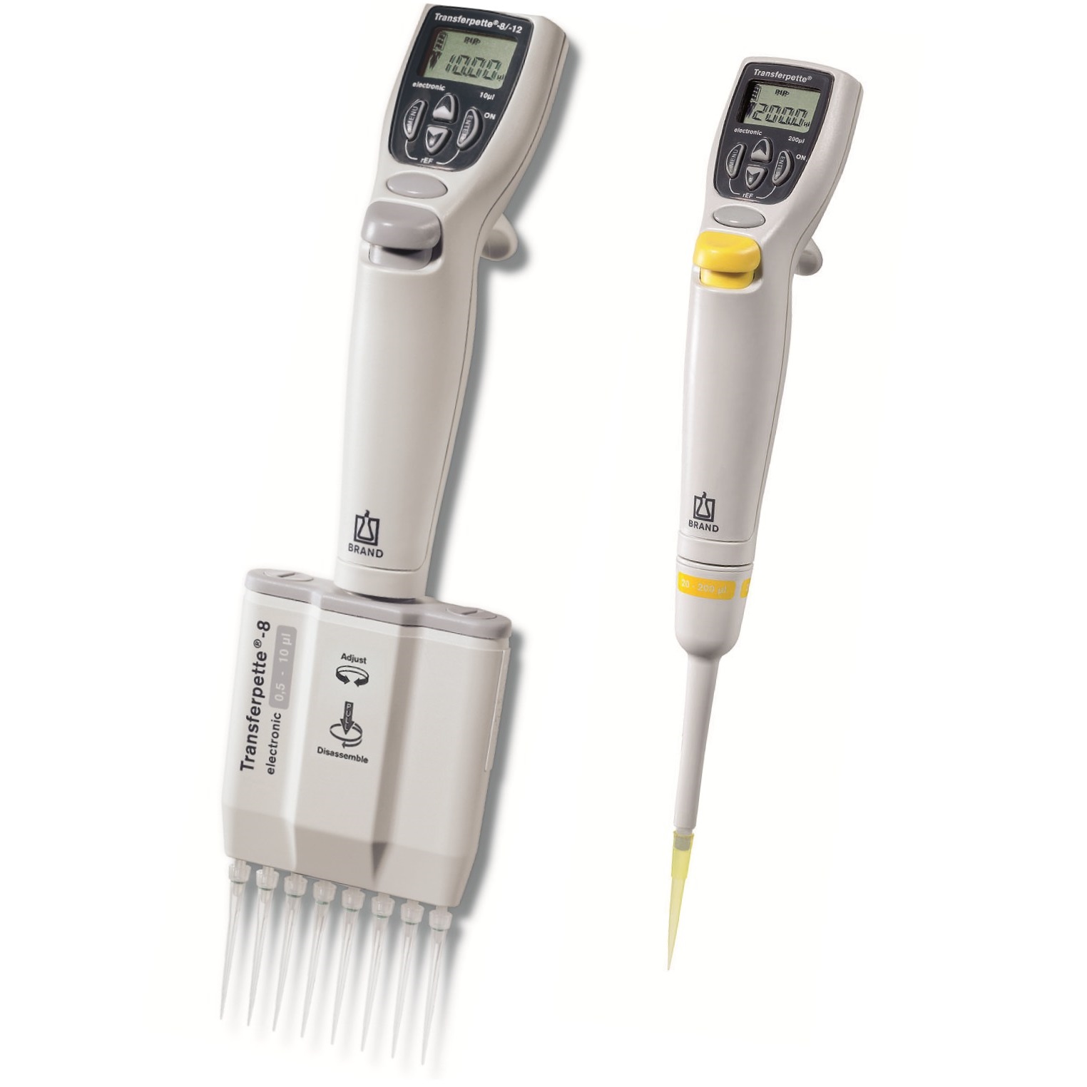
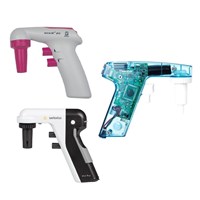
    Brandtech Transferpette pipettes

    Related Posts:
    Transferpette Adjustment Knob Installation, Item # BT 9481
    BrandTech Transferpette Nose Cone Part Numbers
    BrandTech Transferpette S Parts Decoded
    General Troubleshooting – Liquid Leak Test Testing & 12 Point Pipette Inspection

    Disclaimer: Any action you take using the information on this website is strictly at your own risk. The information herein does not constitute professional advice and is general in nature. We make no warranty that this information will meet your requirements, be safe, accurate, or error-free. Pipette Supplies, Inc. is not responsible for any errors or omissions, any results obtained from the use of this information, or any loss or damage arising out of the use of this information. This site is for educational purposes only.
    Fair Use: Copyright Disclaimer under section 107 of the Copyright Act of 1976, allows for “fair use” for purposes such as comments, criticism, teaching, scholarship, news reporting, and research.
    Fair use is permitted by copyright statute that might otherwise be infringing.