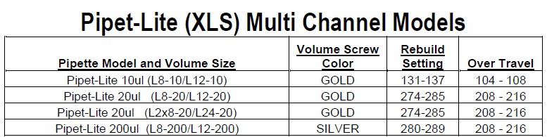
Disclaimer: Any action you take using the information on this website is strictly at your own risk. The information herein does not constitute professional advice and is general in nature. We make no warranty that this information will meet your requirements, be safe, accurate, or error-free. Pipette Supplies, Inc. is not responsible for any errors or omissions, any results obtained from the use of this information, or any loss or damage arising out of the use of this information. This site is for educational purposes only. Fair Use: Copyright Disclaimer under section 107 of the Copyright Act of 1976, allows for “fair use” for purposes such as comments, criticism, teaching, scholarship, news reporting, and research. Fair use is permitted by copyright statute that might otherwise be infringing.
The process of removing, replacing, and reinstalling the Pipet-Lite XLS push rod ejector assembly requires great care, a high attention to detail, patience, and steady hands. Please dedicate a good work area with good lighting and space where small parts can be located should they pop/fly out during disassembly. Pipette damage and lost parts may occur if attention to detail is not maintained. Please proceed at your own risk.
Recommended Service Tools
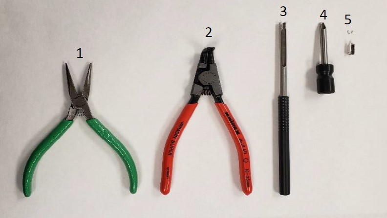
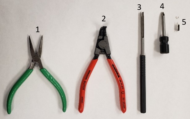
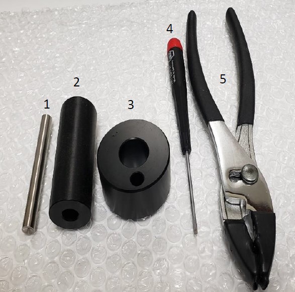
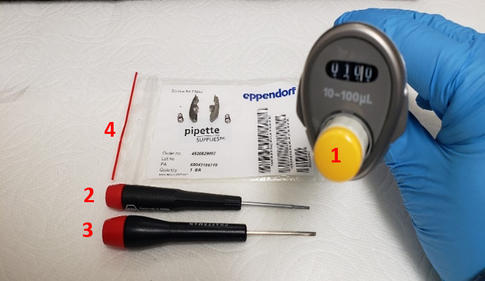
The following tools pictured here are highly recommended to properly service, repair, or replace the push rod ejector assembly, and/or internal volume assembly.
Pipet-Lite XLS / XLS+ Ejector Push Rod Assembly: Part # RA 17012080.
These instructions are only applicable for the Pipet-Lite XLS and XLS+. If you have a Pipet-Lite (not XLS) you can find similar instructions here.
Push Rod Ejector Disassembly Instructions: PIPET-LITE XLS/XLS+
Step 1:
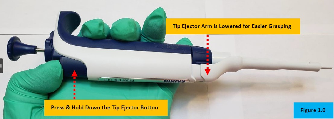
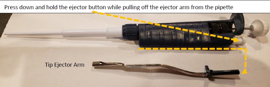
Press and hold down the tip ejector button for easier removal of tip ejector sleeve, as shown in Figure 1.0.
Step 2:
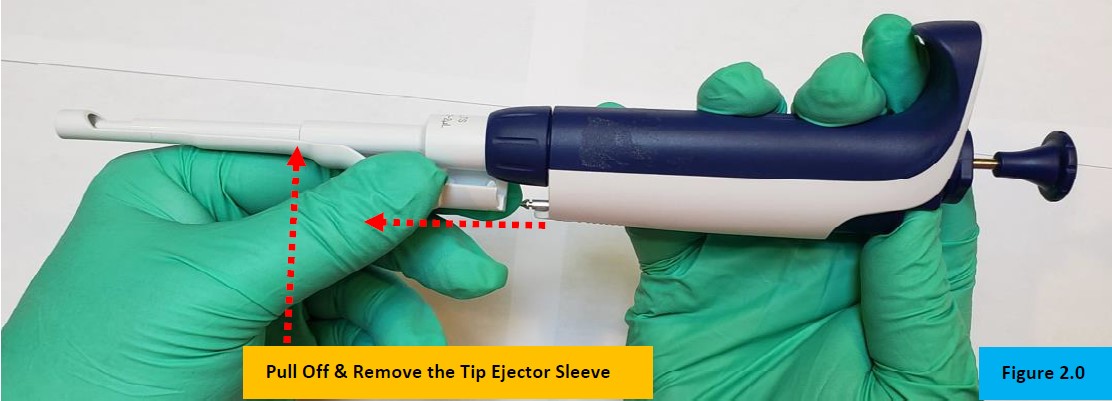
Firmly grasp the tip ejector sleeve and gently pull it in the opposite direction of the pipette handle/body, as shown in Figure 2.0. Lay a side for reassembly.
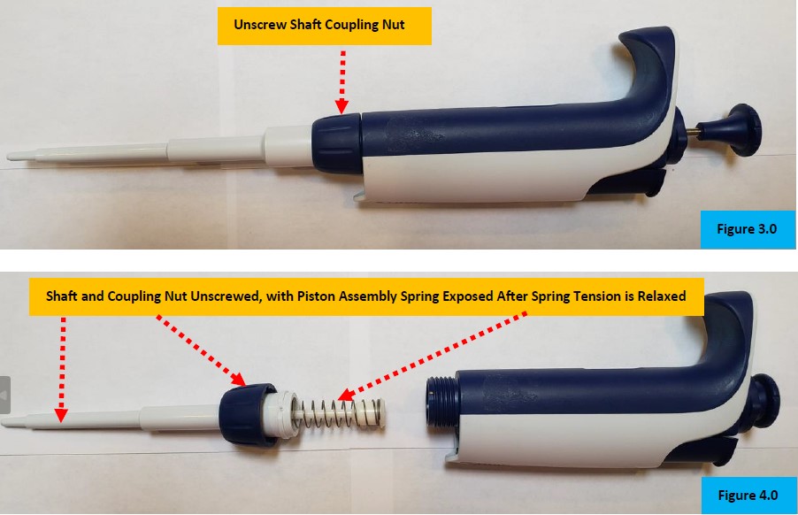
CAUTION: There is a spring and small parts under tension inside of the lower shaft assembly. Use caution as small parts may fly off when the lower shaft is separated from the pipette body.
Step 3:
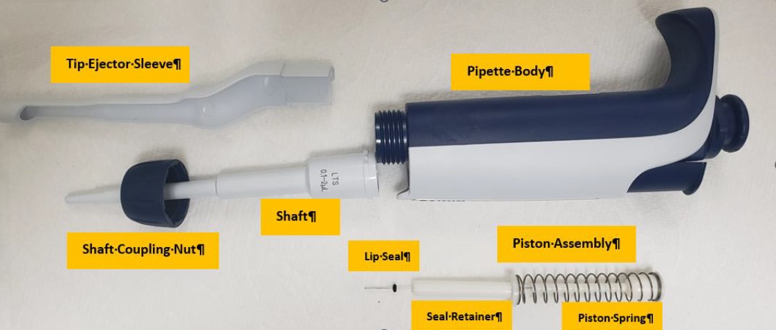
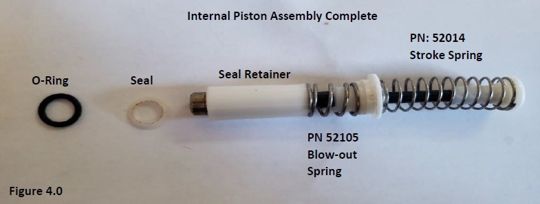
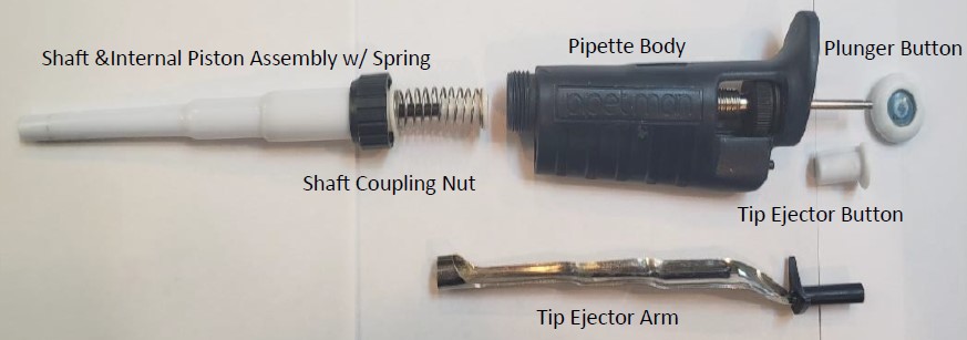
Gently unscrew the shaft coupling nut to separate the lower shaft assembly from the pipette body/handle. See Figure 3.0 & 4.0.
Lip Seal Lubricant Catalog # 2XLSGR55 used to lubricate piston assembly for pipettes with Lip Seals.
NOTE: At this point, routine preventative maintenance (PM) of the piston, spring, seal, o-ring, and shaft components can be performed, if desired.
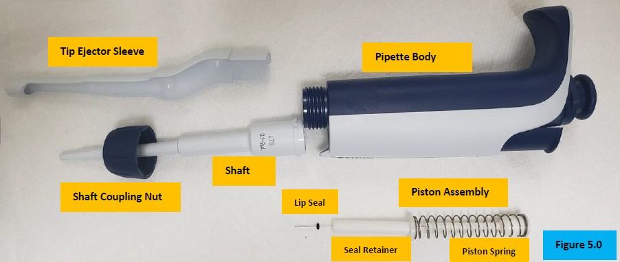
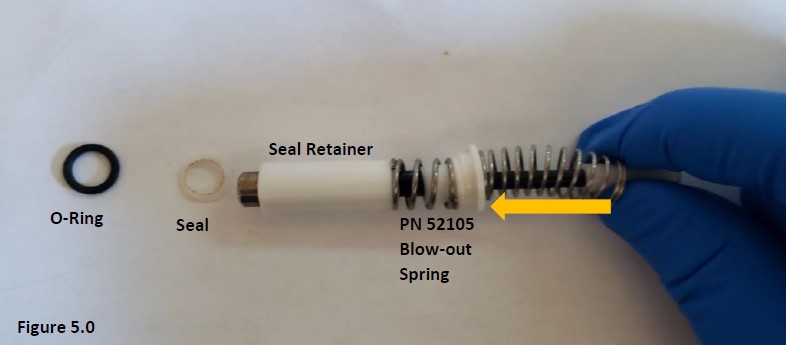
Inspect, clean, lubricate, and/or replace the piston assembly as needed. Examine and replace the seal and o-ring as part of the PM. Inspect and clean the inside of the shaft, and/or replace as needed. Figure 5.0.
Step 4:
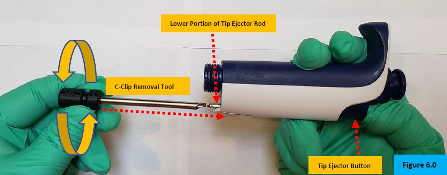
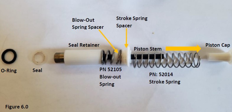
Press and hold down the tip ejector button to expose the lower point of the tip ejector rod, as shown in Figure 6.0.
Step 5:
Slide the C-Clip removal tool onto the ejector rod and firmly push it inward to contact the c-clip(s) that are attached to the ejector rod assembly. Push firmly and twist the tool to dislodge the c-clip(s). Figure 6.0. You may need to do this a couple of times before the clip comes off.
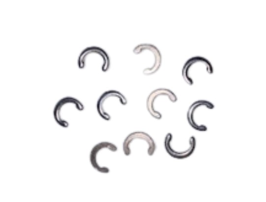
CAUTION: When the c-clips are removed, they may fly off and can easily be lost. Having extra c-clips on hand is highly recommended. Catalog #: PS 1555C (10pk)
Pipet-Lite XLS Push Rod Ejector Assembly – Removal & Access to the Volume/Counter Assembly
Step 6:
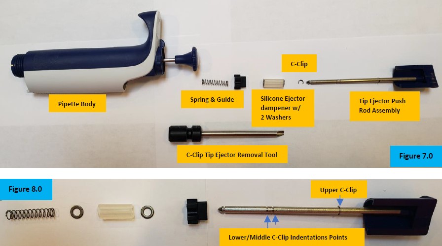
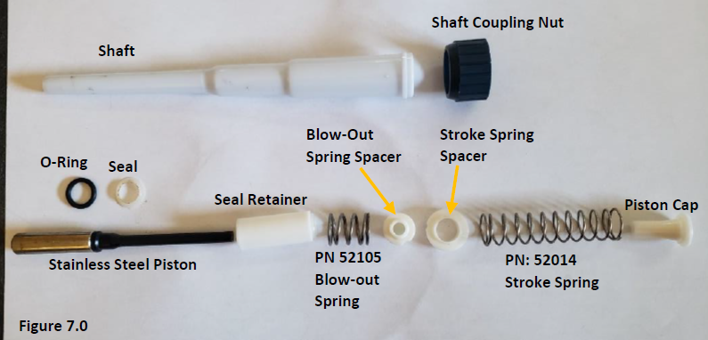
Grasp the tip ejector button and firmly pull upward to remove the tip ejector rod assembly from the top of the pipette body. Put aside for reassembly. Take notice of the parts and their orientation for reassembly. See Figure 7.0 & 8.0.
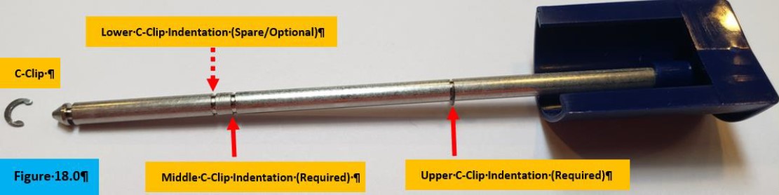
NOTE: Take notice of the lower, middle, & upper indentations where the c-clips will be re-installed later. Upper c-clip is installed for visual. Figure 8.0.
Step 7:
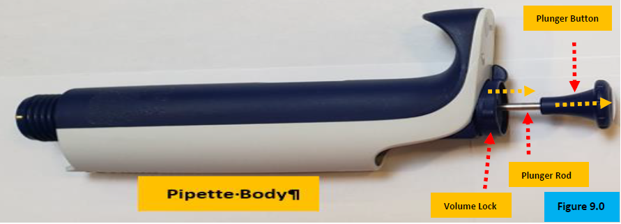
Grasp and firmly pull upward to remove the plunger button. Lay aside. Figure 9.0.
Step 8:
With a small-bladed, flathead screwdriver, gently pry up the volume lock wing to remove the volume lock. Lay it aside.
Step 9:
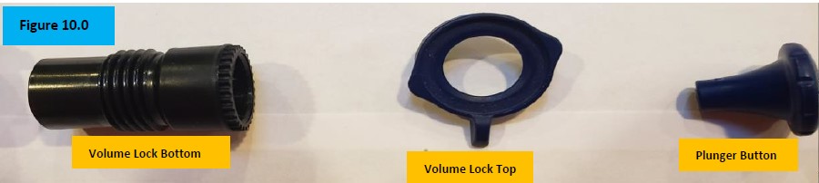
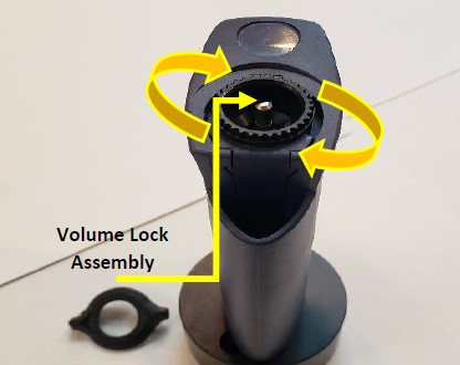
Unscrew fully and remove the volume lock bottom from inside the pipette body. Figure 10.0.
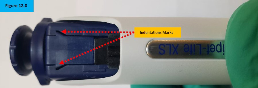
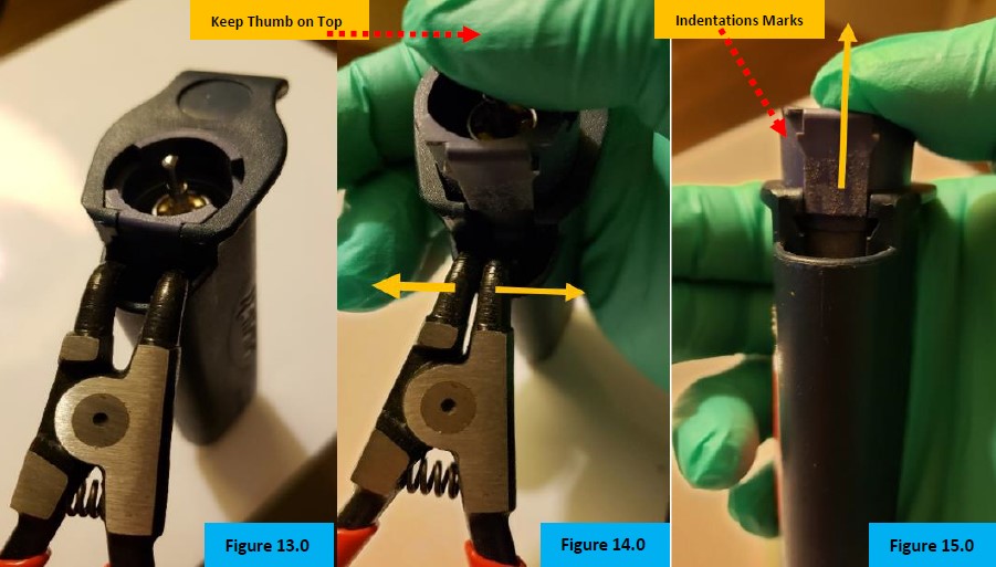
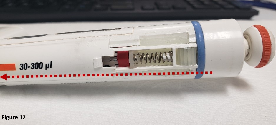
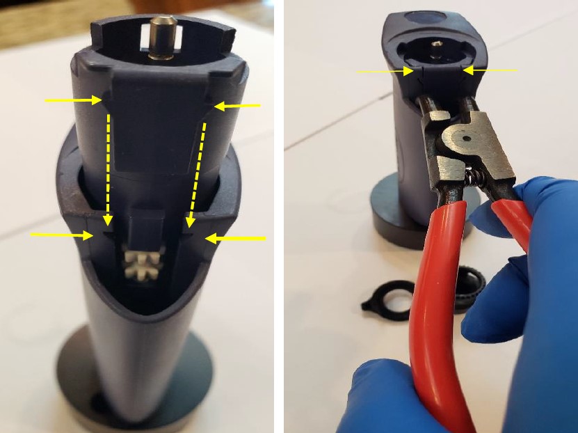
NOTE: Notice the points on the internal volume assembly. These indentations hold the internal volume assembly in place while under tension. These indentations will be spread apart with the bent nosed pliers to remove the internal volume/counter assembly from the pipette body. Figure 12.0.
Step 10:
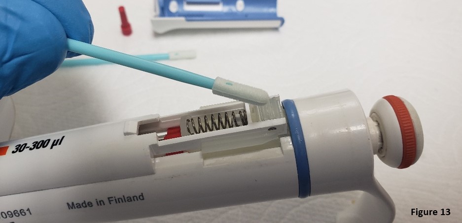
Insert the bent-nosed pliers into the opening vacated by the push rod tip ejector. See Figure 13.0.
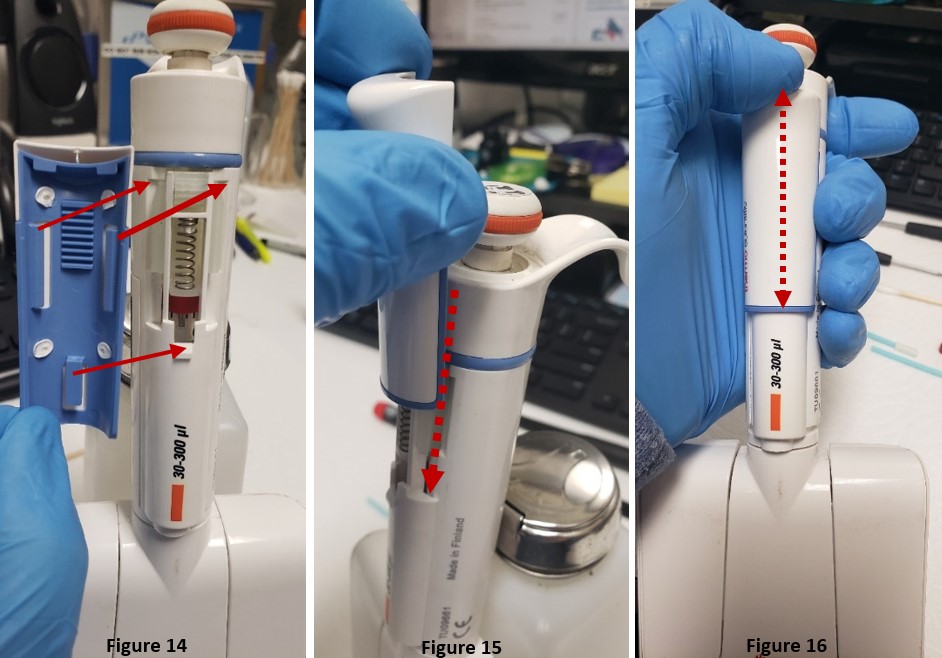
CAUTION: Place thumb on top of the volume assembly prior to step 11. DO NOT REMOVE thumb or internal contents will fly out when step 11 is performed. Figure 14.0.
Step 11:
Gently squeeze the handle of the bent-nosed pliers to have the internal volume assembly pop out of the pipette. Figure 14.0.
Step 12:
Remove the bent-nosed pliers from the pipette body. Ejected Internal volume assembly is now accessible. Figure 15.0.
Step 13:
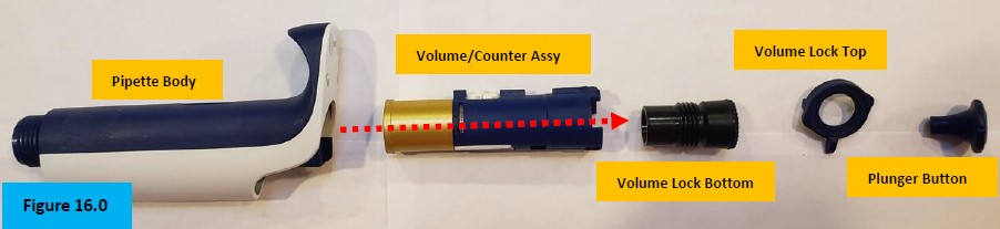
Slide the internal volume/counter assembly out of the pipette. Figure 16.0.
NOTE: The plunger button, volume lock, & volume lock bottom are shown for orientation purposes. The plunger rod and internal spring are not shown in Figure 16.0.
Step 14:
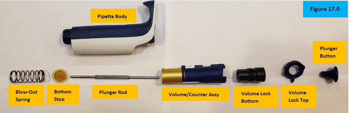
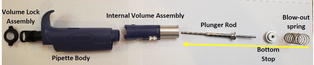
Slide out and remove the plunger rod, internal blowout spring, and bottom stop from the pipette body. Figure 17.0.
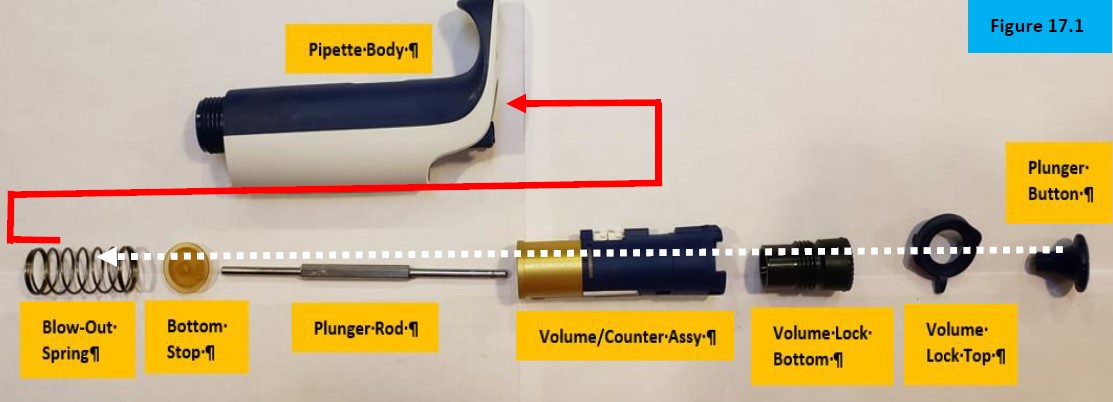
NOTE: Parts are displayed in their proper orientation for reassembly. Figure 17.0
(1) Insert and screw the volume lock bottom back into the volume assembly.
(2) Insert the plunger rod back into the bottom opening of the volume assembly.
(3) Install the bottom stop onto the plunger rod.
(4) Install the blow-out spring onto the bottom stop.
(5) Insert these components into the pipette body opening, spring first.
(6) Install the volume lock top. Wait to install the plunger button until the lower shaft is installed back onto the pipette. Figure 17.1.
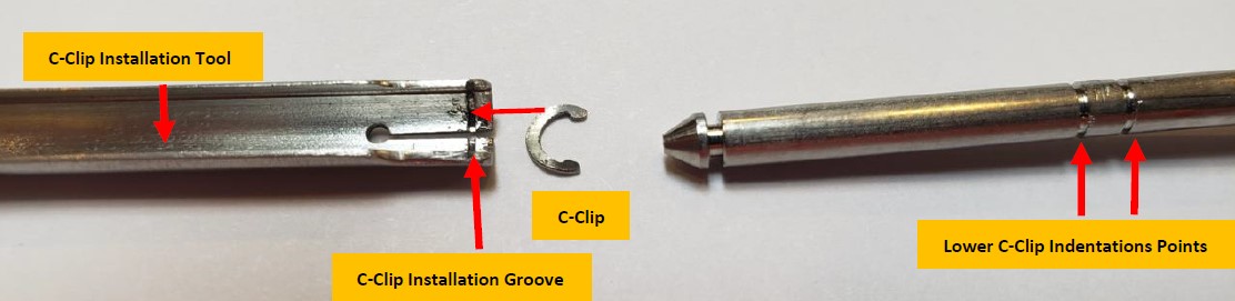
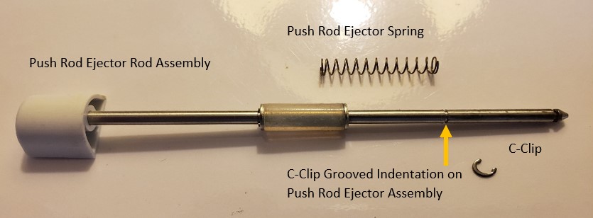
NOTE: Notice the c-clip and 3 indentation marks on the tip ejector rod. A minimum of 2 c-clips are needed for reassembly. The 3rd is optional and, on some occasions, is installed for additional support, or as a spare. Figure 18.0
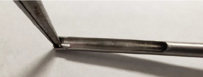
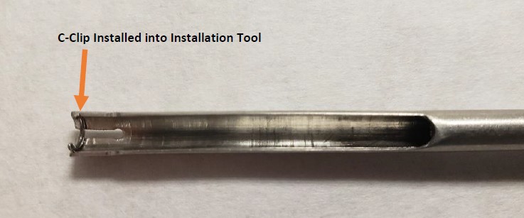
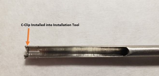
Notice the indentation on the C-Clip installation tool. This is where the c-clip must be installed into for reassembly back onto the push rod ejector assembly.
** Step 17-19B will be completed after Step 22. They are shown below to illustrate the process and allow you to practice. Review these steps first and then return after step 22.**
Step 17:
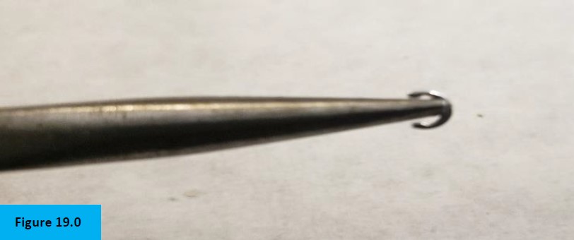
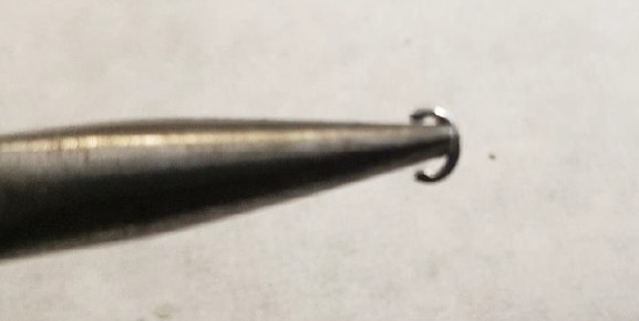
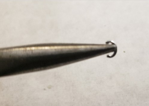
With your needle nose pliers, install the c-clip onto it as shown. Figure 19.0
Step 18:
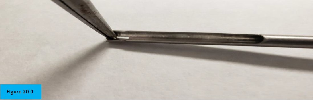
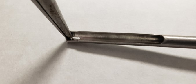
Insert the c-clip into the grooved indentation of the c-clip Installation Tool. Figure 20.0.
NOTE: This is being illustrated for easier viewing. Step would not occur until the push rod ejector assembly is reinstalled into the pipette body.
Step 19:
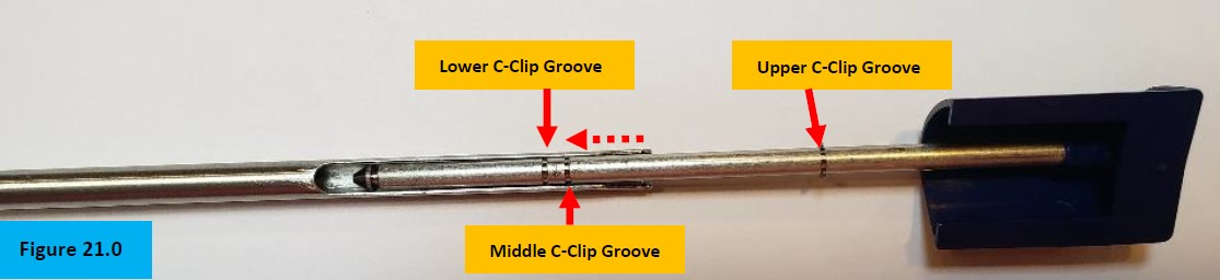
Slide the c-clip installation tool slightly past the middle c-clip insertion groove. Next, drag the tool gently backwards until the c-clip contacts the middle insertion groove. Snap the c-clip in place with the tool. Figure 21.0.
Step 19A:
Install another c-clip onto the c-clip installation tool as described in steps 17-18 above.
Step 19B:
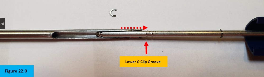
Slide the c-clip installation tool to the lower c-clip groove and snap the c-clip in place. Figure 22.0.
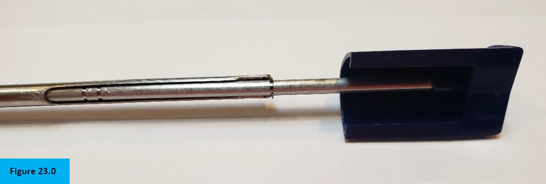
ONLY IF NEEDED: Figure 23.0, the upper c-clip can be re-installed only after the spring, 2 washers, silicone dampener, ejector guide, & lower/middle c-clips are removed. Figure 23.1.
Step 20:
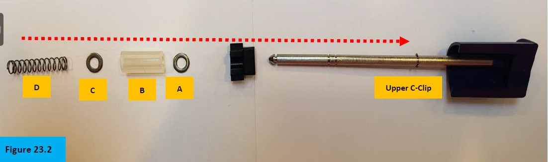
Figure 23.2, Install part (A) onto the Pipet-Lite XLS push rod ejector until butted up to the upper c-clip. Install part (B), followed by part (C) until butted up next to part A. Install part (D) until butted up next to part (C).
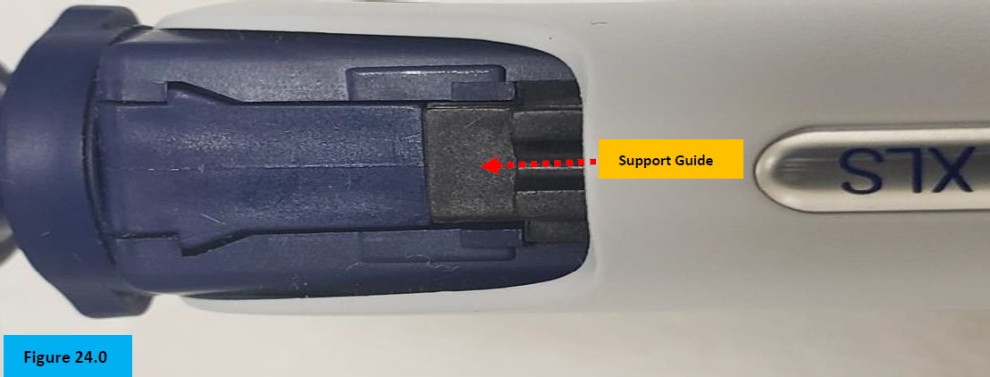
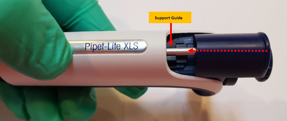
NOTE: The support guide will be installed just prior to inserting the ejector rod assembly back into the pipette body. Notice the orientation and how it sits in the body. Figure 24.0.
Step 21:
Install all components in order, as shown in Figure 23.2.
Step 22:
Just before inserting all components fully into the body, gently align and install the support guide to seat it, prior to pressing the tip ejector button down. When pressing the tip ejector button down, all parts will seat properly and then allow for the c-clips to be re-installed as stated in Steps 17 to Steps 19B. Figures 19.0 – 23.0.
Step 23:
Insert the piston assembly back into the shaft and screw the shaft coupling nut back onto the pipette body. Reattach the tip ejector arm back onto the pipette body. Reassemble the pipette liquid end assembly and allow to equilibrate for at least 60 minutes. Check functionality, accuracy, and precision performance on a 4-5 place balance. You have now completed the Pipet-Lite XLS Push Rod Ejector removal/installation instructions.
Disclaimer: Any action you take using the information on this website is strictly at your own risk. The information herein does not constitute professional advice and is general in nature. We make no warranty that this information will meet your requirements, be safe, accurate, or error-free. Pipette Supplies, Inc. is not responsible for any errors or omissions, any results obtained from the use of this information, or any loss or damage arising out of the use of this information. This site is for educational purposes only. Fair Use: Copyright Disclaimer under section 107 of the Copyright Act of 1976, allows for “fair use” for purposes such as comments, criticism, teaching, scholarship, news reporting, and research. Fair use is permitted by copyright statute that might otherwise be infringing.
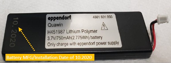
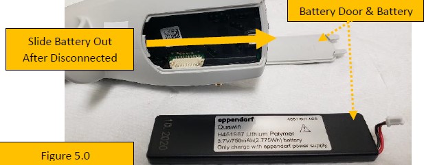
The Eppendorf Xplorer uses a 3.7V, 750mAh Lithium Polymer battery that provides many hours of reliable use and operation. In most cases, the battery will provide between 300-500 complete recharging cycles before replacement is needed. This equates to roughly 3-5 years with proper use. With this battery, the mfg./install date was 10.2020 meaning possible replacement could occur between October 2023-2025.
Of course, battery replacement depends on several factors including but not limited to:
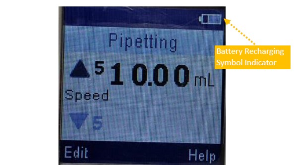
Will it recharge? What does the LCD battery logo show?
Are you using the manufacturer recommended wall power supply (WPS) and recharging stand? (strongly recommended)
Are you storing the pipette and battery in a cool, comfortable, and ambient-like conditions?
When not in use, is the battery being stored at 40%-50% of capacity to help prolong battery life?
Remember: DO NOT over charge or over discharge battery. Most pipettes have built in processes to regulate this from occurring, but it’s worth noting.
Xplorer Battery Replacement Instructions
Step 1:
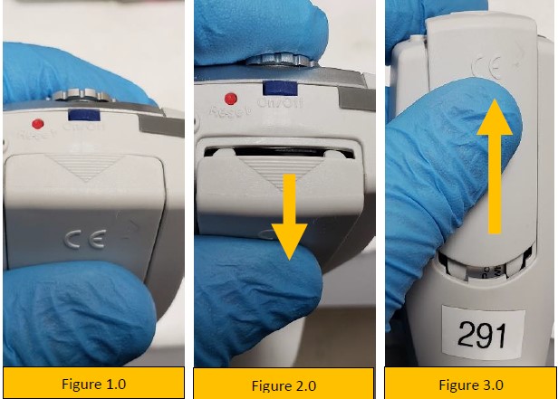
Gently pry open the battery door by lifting outward, as shown by the triangle logo on the battery door (figure 2.0).
Step 2:
Slide battery door upward (figure 3.0) and remove fully. Lay it aside.
Step 3:
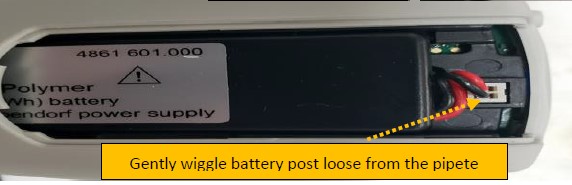
With the battery door removed, gently wiggle the white colored battery post until it unplugs from the pipette (figure 5.0).
Step 4:
After disconnecting the battery, slide it up and out of the battery compartment (figure 5.0).
Step 5:
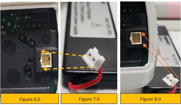
Notice the pin alignment of the battery port and the port itself (figures 6.0, 7.0, and 8.0). This is important for proper battery alignment and insertion.
Step 6:
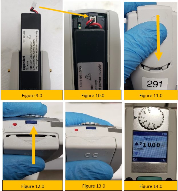
Slide the new battery into the pipette battery compartment (figure 9.0).
Step 7:
Align, connect, and plug-in the battery to the battery port (figures 6.0, 7.0, 8.0 and 10.0).
Step 8:
Slide the battery compartment door onto the pipette (figure 11.0).
Step 9:
As shown in figure 12.0, snap the battery door back into place with your thumb and index finger until it looks like figure 13.0.
Step 10:
Turn on the pipette and recharge the new battery until fully charged. Approximately 60-90 minutes.
Disclaimer: Any action you take using the information on this website is strictly at your own risk. The information herein does not constitute professional advice and is general in nature. We make no warranty that this information will meet your requirements, be safe, accurate, or error-free. Pipette Supplies, Inc. is not responsible for any errors or omissions, any results obtained from the use of this information, or any loss or damage arising out of the use of this information. This site is for educational purposes only. Fair Use: Copyright Disclaimer under section 107 of the Copyright Act of 1976, allows for “fair use” for purposes such as comments, criticism, teaching, scholarship, news reporting, and research. Fair use is permitted by copyright statute that might otherwise be infringing.
Gilson Pipetman Piston Return/Stroke Spring, Long: 52104 (The terms ‘return spring’ and ‘stroke spring’ refer to the same part)
Gilson Pipetman Piston Purge/Blow-out Spring, Short: 52105 (The terms ‘purge spring’ and ‘blow-out spring’ refer to the same part)
Pipetman Piston Assembly, P1000, P1000N, F250 to F1000: GI F123847
Step 1:
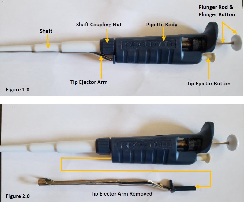
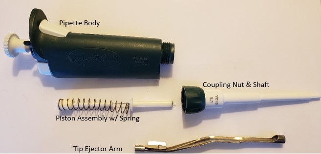
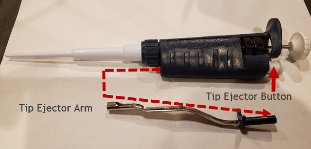
Press and hold the tip ejector button in the down position (figure 1.0) while detaching the tip ejector arm from the pipette body (figure 2.0). Figure 2.0 shows the tip ejector arm removed.
Step 2:
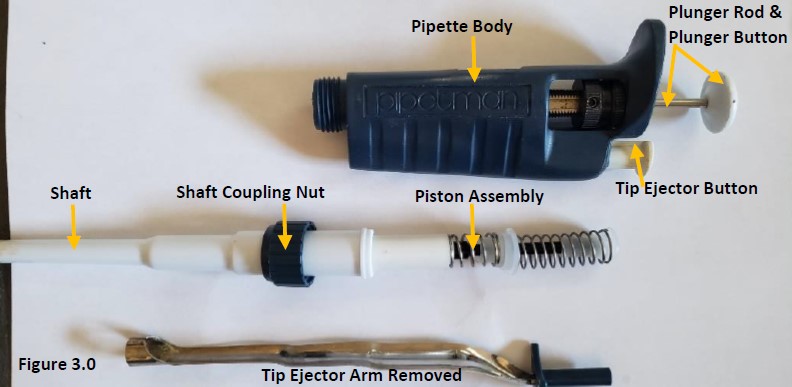
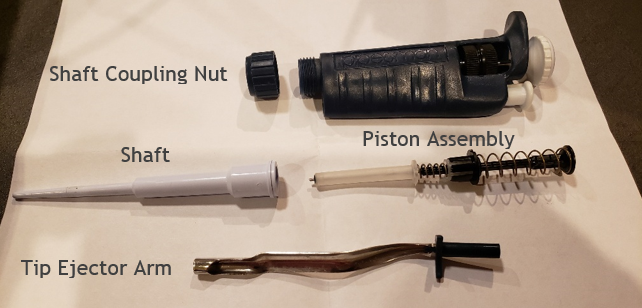
Carefully unscrew the coupling nut and shaft (figure 1.0) from the pipette body. There is an internal piston assembly and springs that may pop out when unscrewed and removed from the shaft (figure 3.0). Remove the piston assembly from the shaft and lay aside.
Step 3:
Remove the seal and o-ring from the piston and inspect for wear, dirt, and chemical splash. Lay them aside for replacement. Inspect the stainless-steel piston for wear, chemical splash, rust, pit mark or scratches. Replace piston assembly if needed. NOTE: A new piston assembly (GI F123847) includes a return spring.
Step 4:
To replace the return spring (52104), press in and hold to collapse the spring (figure 5.0).
Step 5:
With the return spring still collapsed, firmly pull off and remove the piston cap from the piston stem and lay aside. Allow the return spring to relax and return to normal length (figure 6.0).
Step 6:
In figure 7.0, the piston cap, return spring, return spring spacer, purge/blow-out spring spacer, purge spring (52105), seal retainer, stainless steel piston, seal, and o-ring are shown in order and orientation for reassembly.
Step 7:
Install and slide the stainless-steel piston into the seal retainer.
Step 8:
Re-install or install a new blow-out/purge spring (52105) onto the seal retainer.
Step 9:
Install a new purge spring spacer onto the purge spring, then install & seal the new return/stroke spring spacer onto the purge spring spacer & return spring.
Step 10:
Install the piston cap back onto the piston stem. See figure 4.0 for correct assembly.
Step 11:
Insert piston assembly into the shaft (figure 3.0).
Step 12:
Screw the shaft with the shaft coupling nut back onto the pipette body (figure 2.0). Final assembly should look like figure 1.0.
Step 13:
After reassembly, allow the pipette to equilibrate for at least 60 minutes then confirm accuracy and precision on a 4-place balance. Re-check work if needed.
Disclaimer: Any action you take using the information on this website is strictly at your own risk. The information herein does not constitute professional advice and is general in nature. We make no warranty that this information will meet your requirements, be safe, accurate, or error-free. Pipette Supplies, Inc. is not responsible for any errors or omissions, any results obtained from the use of this information, or any loss or damage arising out of the use of this information. This site is for educational purposes only. Fair Use: Copyright Disclaimer under section 107 of the Copyright Act of 1976, allows for “fair use” for purposes such as comments, criticism, teaching, scholarship, news reporting, and research. Fair use is permitted by copyright statute that might otherwise be infringing.
The process of removing, replacing, and reinstalling the F1 tip ejector pusher upper and lower slide mechanisms require great care, a high attention to detail, patience, and steady hands. Please dedicate a good work area with good lighting and space where small parts can be located should they pop/fly out during disassembly. Pipette damage and lost parts may occur if attention to detail is not maintained. Please proceed at your own risk.
Finnpipette F1 and F2 Tip Ejector Mechanism Replacement – Pusher Upper Part and Lower Slide.
These instructions are applicable for both single channel and multichannel Finnpipette F1, F1 ClipTip, and F2 pipettes.
Disassembly Process:
Step 1:
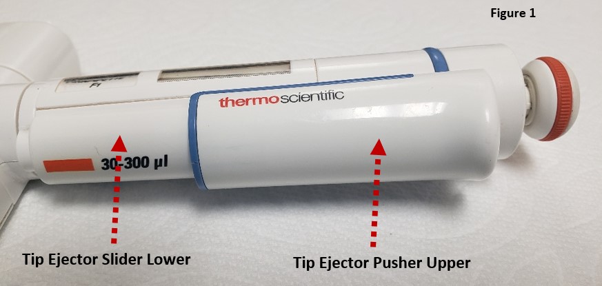
The ejector mechanism is made up of two components: the tip ejector pusher upper part and the tip ejector slider lower part. Check and become familiar with these parts.
Step 2:
Press the ejector button down and hold.
Step 3:
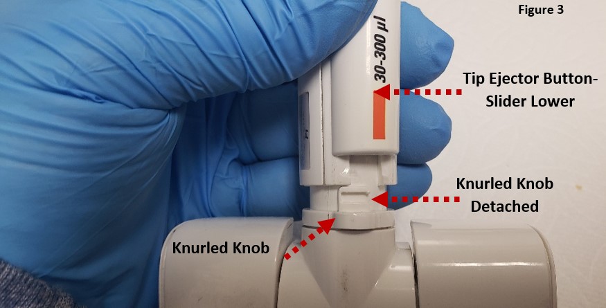
Gently rotate the white colored knurled knob clockwise to detach it from the tip ejector slider lower part.
Step 4:
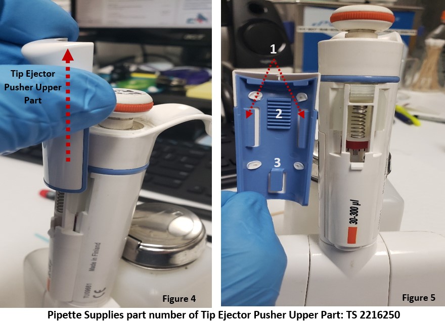
With your thumb, gently push upward on the tip ejector pusher upper part to separate it from the tip ejector slider lower piece, per figure 4.
Note: You may need to use a small-bladed tool like a screwdriver to gently pry up one side of the tip ejector upper part if it does not come detached when pressing upward with your thumb. See figure 4.
Notice: The blue colored backside of the tip ejector pusher upper part contains:
Left & Right-side rail tabs.
Grooved cog wheel lines.
Lower locking tab
Ensure none are broken off or missing. If so, replace.
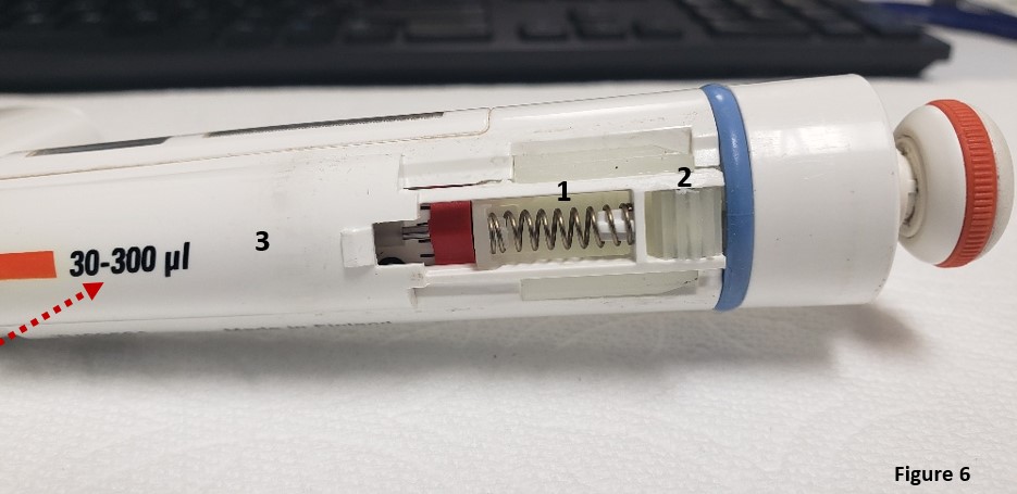
Observation: With the tip ejector pusher upper part removed, notice the components of the tip ejector slider lower part:
Tip ejector slider lower part: (varies based on imprinted volume size [F1, F2])
These parts may pop off and get lost, be careful.
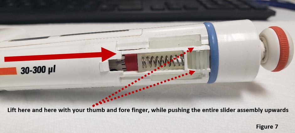
Step 5:
Gently lift outwards the cog wheel assembly, while pushing the entire tip ejector slider assembly lower part upward.
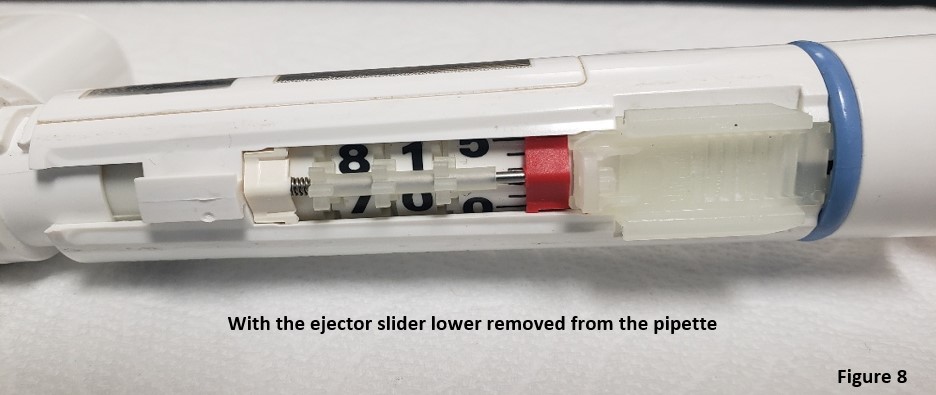
With the ejector slider lower part removed, the pipette will look as pictured in figure 8.
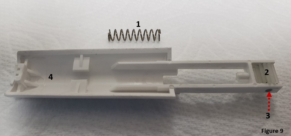
Step 6: Remove and replace parts (F1, F2) as needed:
Tip ejector slider spring
Cog Wheel
Cog Wheel Pin
Tip ejector slider lower assembly
Reassembly Process:
Step 7:
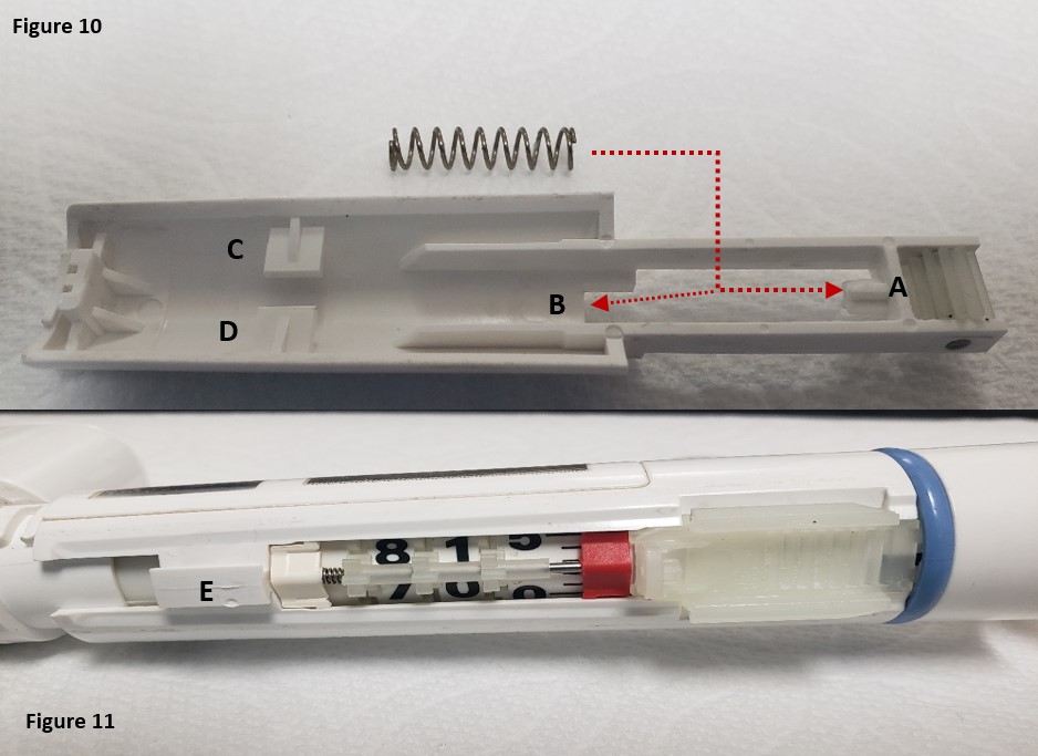
Insert new or existing spring back onto the upper (A) and lower (B) posts as shown in figure 10. Replace the pin in the cog wheel and then the cog wheel itself, as needed.
Notice: Support tabs C and D in figure 10 will be fitted into post E on the pipette body.
Step 8: Align tabs C & D into post E from figures 10 and 11. Fully slide the Finnpipette F1 / F2 tip ejector slider lower part back onto the pipette body as shown in figure 12.
Step 9:
As recommended by ThermoScientific Technical Support, place a “minute” amount of TS 3300200 1g grease onto a foam swab or lint-free towel. Very lightly grease the cog wheel with a very small of grease.
Step 10:
Refer to step 4, figure 5 by aligning the left and right-side tabs with the pipette ejector slider lower part, as in figure 14.
Step 11:
Slide the ejector pusher upper part back onto the pipette, as shown in figure 15. It should snap/click back into place once seated properly.
Step 12:
Lastly, press the tip ejector button a few times to ensure it is seated and working properly (Figure 16). Then test by loading and ejecting tips. Recheck your work, if needed.
Disclaimer: Any action you take using the information on this website is strictly at your own risk. The information herein does not constitute professional advice and is general in nature. We make no warranty that this information will meet your requirements, be safe, accurate, or error-free. Pipette Supplies, Inc. is not responsible for any errors or omissions, any results obtained from the use of this information, or any loss or damage arising out of the use of this information. This site is for educational purposes only. Fair Use: Copyright Disclaimer under section 107 of the Copyright Act of 1976, allows for “fair use” for purposes such as comments, criticism, teaching, scholarship, news reporting, and research. Fair use is permitted by copyright statute that might otherwise be infringing.
The process of removing, replacing, and reinstalling the Rainin Pipet-Lite/Pipet-Lite XLS/PIpet-Lite XLS+ Counter Assembly requires great care, a high attention to detail, patience, and steady hands. Please dedicate a good work area with good lighting and space where small parts can be located should they pop/fly out during disassembly. Pipette damage and lost parts may occur if attention to detail is not maintained. Please proceed at your own risk.
Recommended Service Tools
The following tools are strongly recommended to properly service, repair, or replace the Rainin push rod ejector assembly and/or the internal volume assembly.
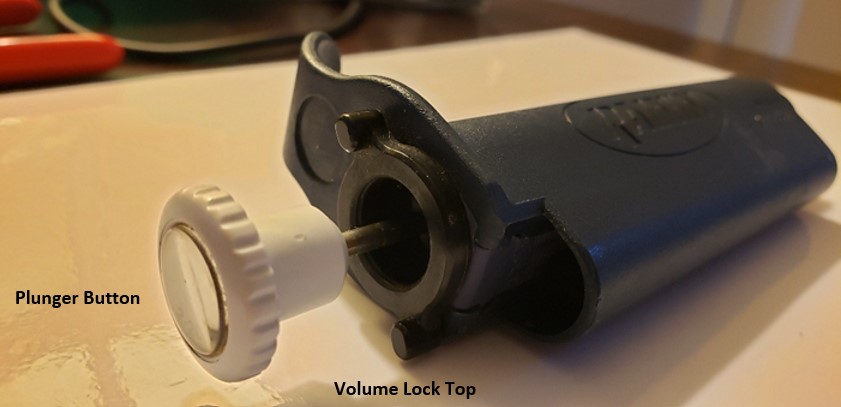
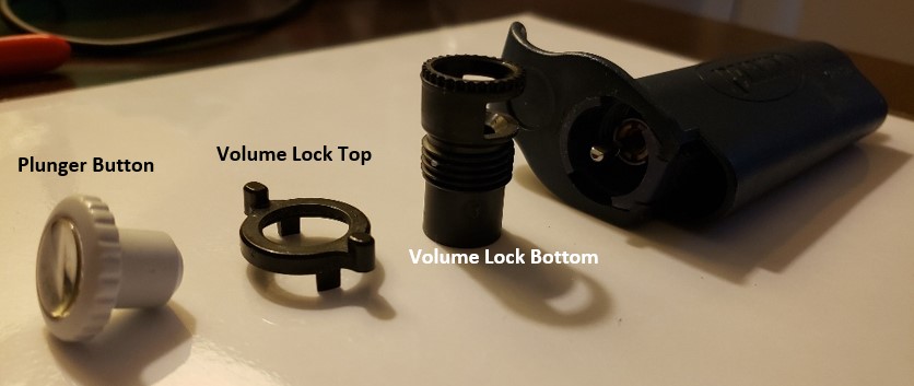
Remove the plunger button, volume lock top, and volume lock bottom from the pipette handle. The plunger button and volume lock top can be pulled directly off the pipette.
Step 3:
Unscrew the volume lock bottom and remove it from the pipette body.
Step 4:
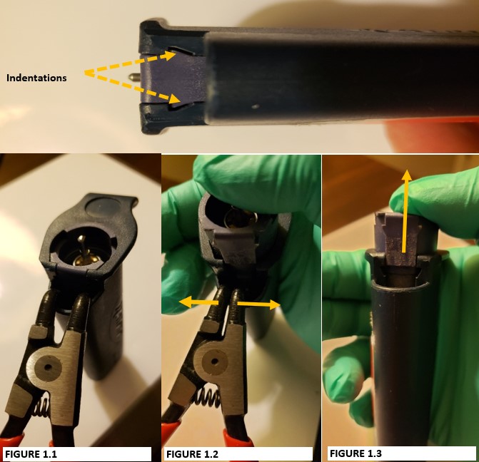
Notice the indentations on the internal volume assembly. These indentations will be spread apart with the bent-nosed pliers to remove the internal volume assembly from the pipette body.
CAUTION: Place your thumb on top of the volume assembly prior to step 5. DO NOT remove your thumb or internal contents will fly out when step 5 is performed.
Step 5:
Insert the bent-nosed pliers into the opening that is vacated by the tip ejector button (Figure 1.1). Gently squeeze the handle of the bent-nosed pliers to have the internal volume assembly pop out of the pipette (Figure 1.2).
Step 6:
Remove the bent-nosed pliers from the pipette body. Internal volume assembly is now accessible as in figure 1.3
Step 7:
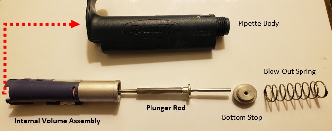
With the internal volume assembly removed from the pipette, remove the:
Blow-out spring from the pipette body
Bottom stop
Plunger rod
Step 8:
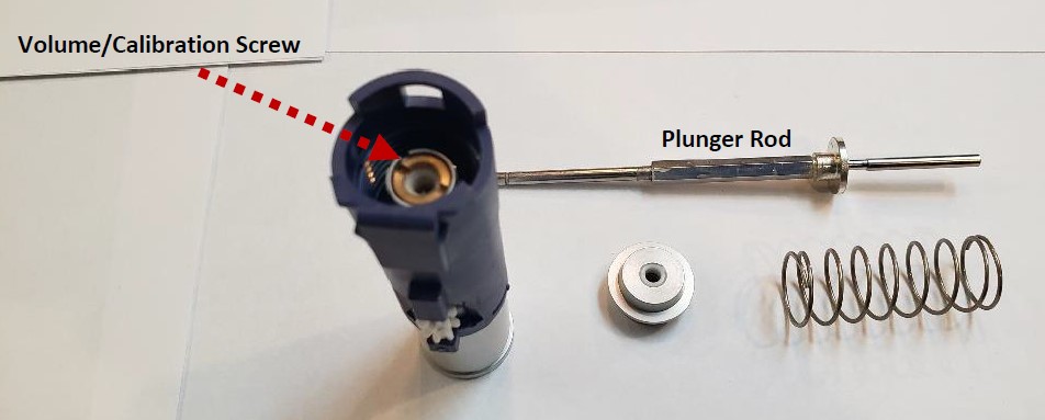
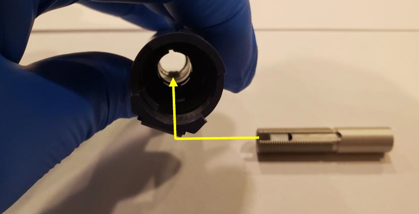
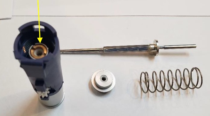
Notice the volume/calibration screw seated in the volume assembly. This will be removed next with the plunger rod.
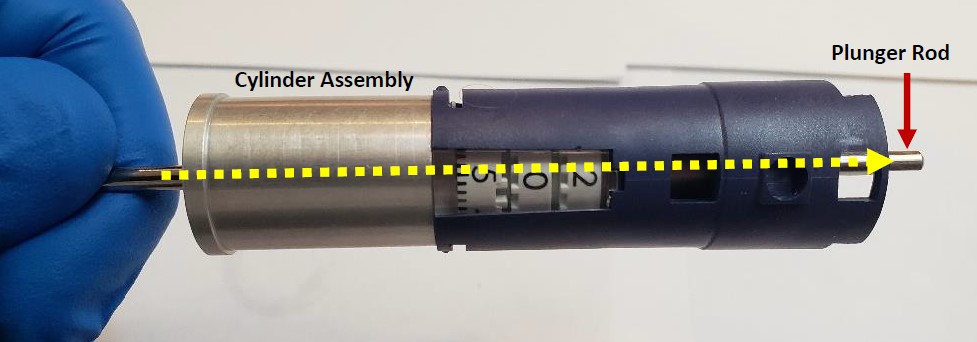
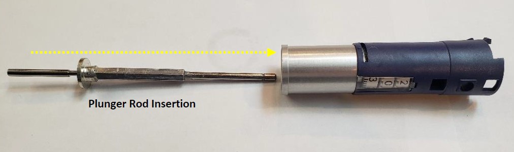
Insert the plunger rod fully into the bottom (silver colored) cylinder assembly until the plunger rod is visible from the top of the volume assembly as shown below.
Step 9:
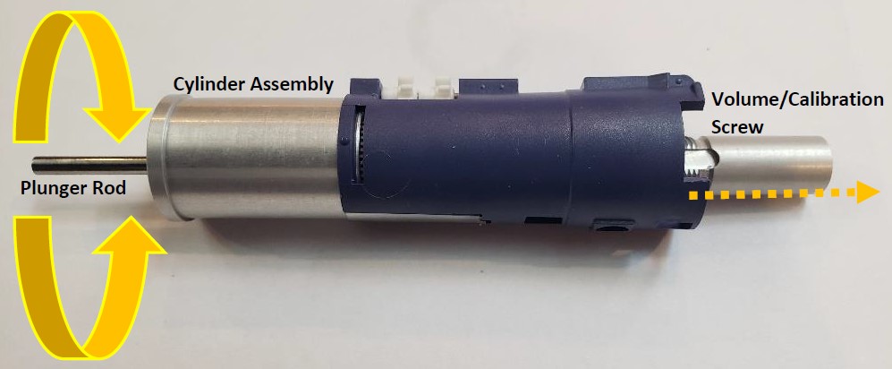
Rotate the plunger rod (the display digits will wind upwards) until the silver/brass colored volume/calibration screw disconnects and can be removed by hand.
NOTE: Remember to write down the digits of the Pipet-Lite counter assembly once the volume/calibration screw is removed. This information will be useful during reassembly.
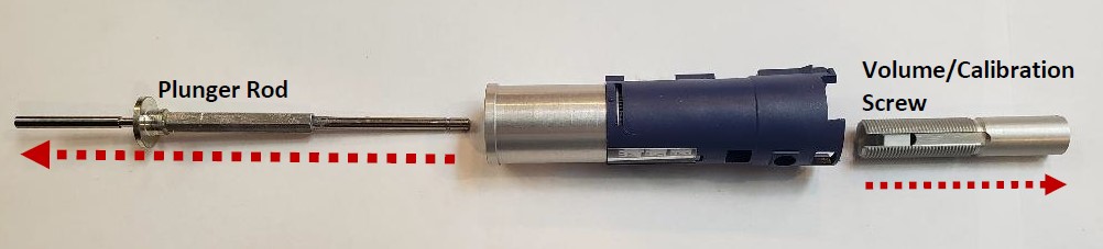
The picture below shows the volume calibration screw fully removed from the top of the pipette, and plunger rod removed from the bottom of the pipette.
Step 10:
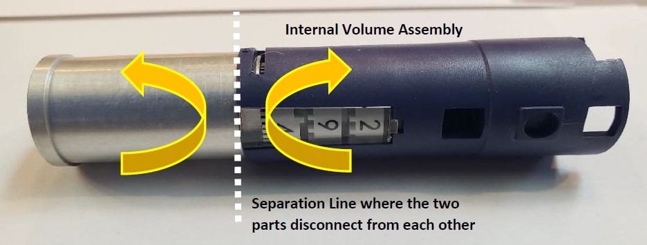
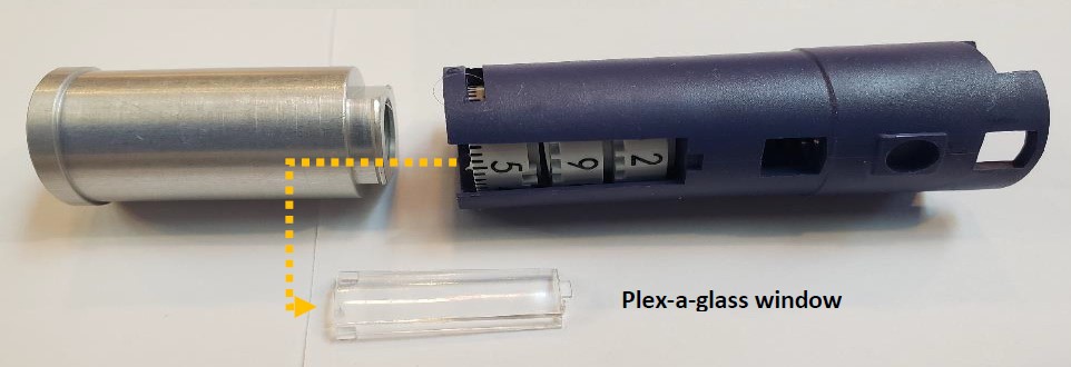
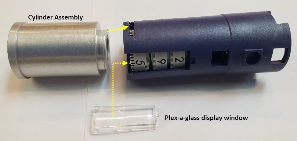
In this step, the silver cylinder assembly will be separated and removed from the volume assembly. Place the cylinder assembly in the left hand and the volume assembly in the right hand. With your thumbs, gently push upward to separate these two parts from each other
Step 11:
Slide the display plex-a-glass window out.
Step 12:
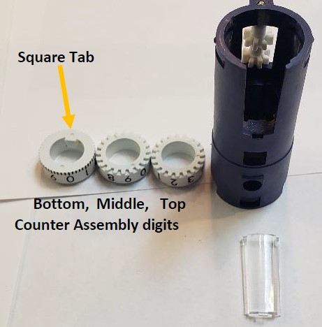
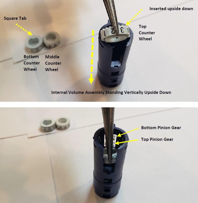
Turn the volume assembly vertically and remove the three (3) white colored digits.
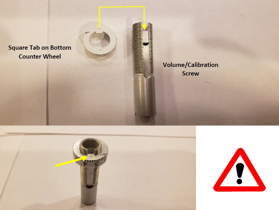
NOTE: Notice the square tab on the bottom digit. This will be important for reassembly of the volume/calibration screw.
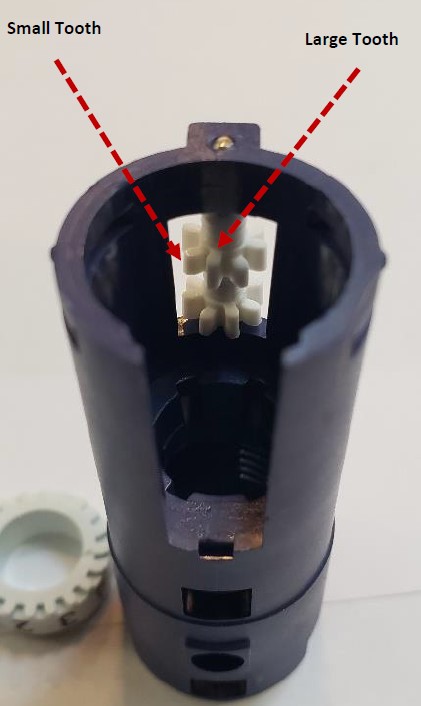
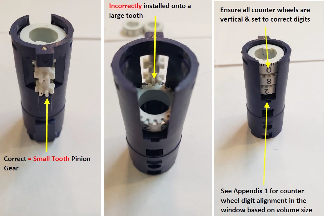
NOTE: During reassembly of the Pipet-Lite counter assembly digits, the top and middle digits will need to be placed on a “small tooth”. DO NOT align them on a “large tooth” as this could lead to the digits not aligning fully in a straight line.
Step 13:
With the counter assembly standing vertically upside down, use a pair of needle nose pliers to insert:
The top counter wheel first onto the top pinion gear “small tooth”
insert the middle counter wheel onto the bottom pinion gear “small tooth”
insert/lay the bottom counter wheel on top of the middle counter wheel
IMPORTANT: The top and middle counter wheels must be inserted into the volume assembly upside down and seat onto a “small pinion gear tooth,” as shown.
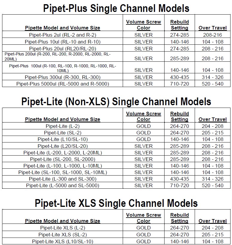
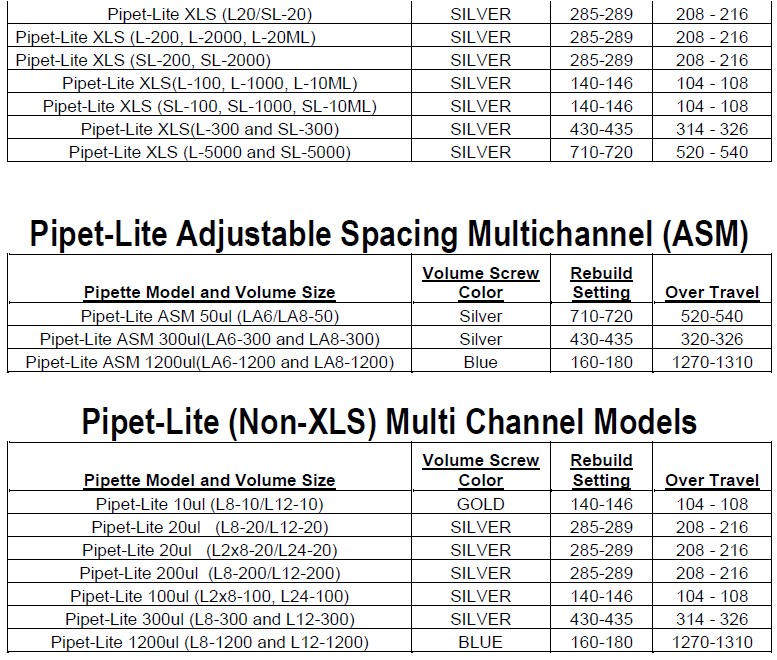
IMPORTANT: when inserting the counter wheels, ensure the correct digits are visible in the window based on pipette volume size. See Appendix 1
Step 14:
Insert the display window back into the volume assembly. Install and snap the silver cylinder assembly back onto the volume assembly.
Step 15:
Notice the volume/calibration screw and the square tab on the bottom counter wheel. The square tab must align with the slot track on the volume/calibration screw.
Step 16:
In this step, the volume/calibration screw will be re-inserted into the internal volume assembly.
IMPORTANT: Look down inside the volume assembly and align the volume/calibration screw with the square tab on the bottom counter wheel.
Fully insert the volume/calibration screw into the internal volume assembly. Make sure it is inserted fully.
Step 17:
Insert the plunger rod fully into the bottom of the pipette through the silver cylinder assembly.
Once fully inserted, wind the plunger so the volume of the counter wheels wind down to the 10% of nominal.
It’s strongly recommended the internal volume assembly be rotated vertically so the calibration screw is threaded fully into the unit.
Step 18:
Place the bottom stop onto the plunger rod. Insert the blow-out spring down inside the empty pipette body. Install the plunger rod into the internal volume assembly.
Step 19:
Notice the pointed edges of the internal volume assembly. Using the bent nosed pliers, gently spread and enlarge the body opening, while pushing down on the internal volume assembly to align and lock it in the pipette body.
Step 20:
Insert the volume lock bottom into the pipette body and screw it only finger tight. DO NOT over tighten or it will take much more force to lock and unlock the volume lock. Next, snap the volume lock top back onto the pipette.
Place the plunger button back on the pipette.
Screw the shaft assembly back onto the pipette body.
Step 21:
With the needle-nosed pliers, gently grab and hold a c-clip onto the nubs of the pliers as shown in the photo below.
Step 22:
Insert the c-clip into the grooved indentation on the c-clip installation tool.
Step 23:
Notice the c-clip inserted into the grooved indentation on the c-clip installation tool.
Step 24:
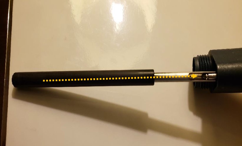
Push and hold the ejector button. Gently slide the installation tool fully into the pointed end of push rod ejector rod assembly until the c-clip catches with the c-clip grooved indentation on the push rod ejector assembly as shown in the picture on step 8 of Rainin Push Rod Ejector Assembly Replacement.
Step 25:
Push the c-clip tool upward to snap the c-clip back in place until you hear a slight click.
Step 26:
Reattach the tip ejector arm back onto the pipette body.
Disclaimer: Any action you take using the information on this website is strictly at your own risk. The information herein does not constitute professional advice and is general in nature. We make no warranty that this information will meet your requirements, be safe, accurate, or error-free. Pipette Supplies, Inc. is not responsible for any errors or omissions, any results obtained from the use of this information, or any loss or damage arising out of the use of this information. This site is for educational purposes only. Fair Use: Copyright Disclaimer under section 107 of the Copyright Act of 1976, allows for “fair use” for purposes such as comments, criticism, teaching, scholarship, news reporting, and research. Fair use is permitted by copyright statute that might otherwise be infringing.
The process of removing, replacing, and reinstalling the Pipetman Push Rod Ejector Assembly requires great care, a high attention to detail, patience, and steady hands. Please dedicate a good work area with good lighting and space where small parts can be located should they pop/fly out during disassembly. Pipette damage and lost parts may occur if attention to detail is not maintained. Please proceed at your own risk.
These instructions are ONLY applicable for Gilson Pipetman Single Channel and Multichannel Pipettes that use this ejector rod system: GI F144872. This includes Pipetman pipettes with tip ejectors that have the blue plastic piece.
Recommended Service Tools
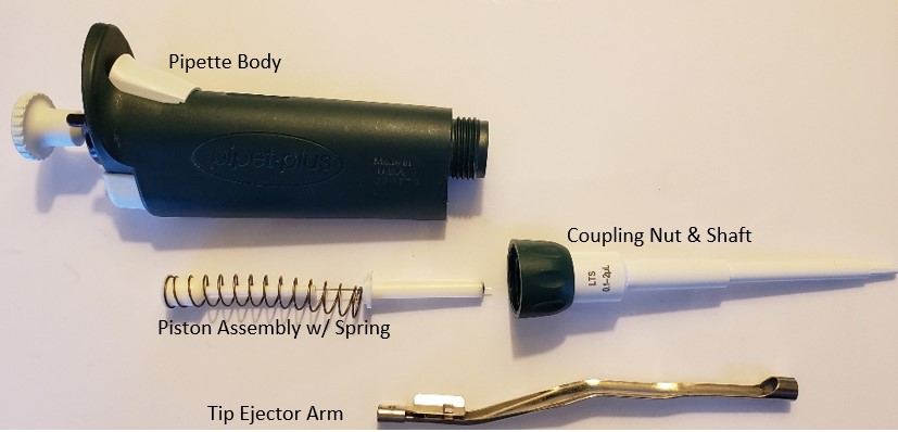
The following tools pictured here are strongly recommended to properly service, repair, or replace the Gilson Pipetman push rod ejector assembly.
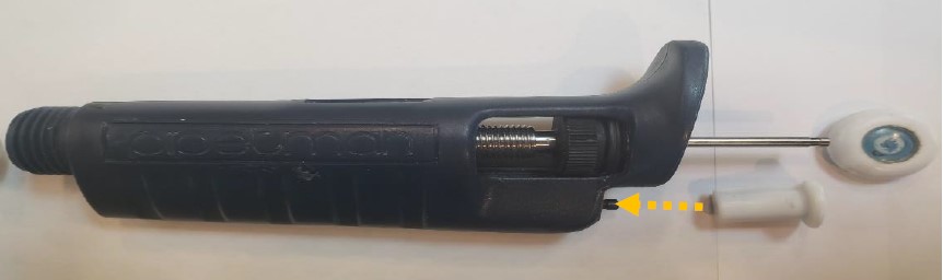
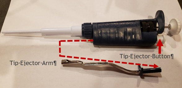
Remove the tip ejector arm from the pipette by pressing and holding down the white colored ejector button. With the button held down, pull off the tip ejector arm and lay aside for reassembly.
Step 2:
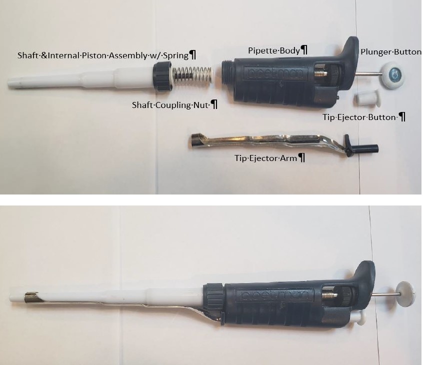
Unscrew the shaft coupling nut. Remove the shaft and internal piston assembly.
CAUTION: Be careful when unscrewing the coupling nut. The piston spring is under tension and may fly out with the piston assembly parts. Lay the piston assembly, shaft, and shaft coupling nut next to the tip ejector arm for reassembly later.
Step 2A:
Pull off the plunger button and use the pliers with rubber nibs to remove the ejector button.
Step 3:
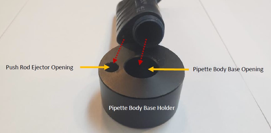
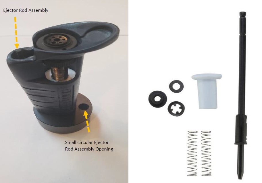
Notice the two circular openings of the platen holder, pictured below. The large circular opening is used to hold the pipette vertically in the holder The small circular opening is for the push rod ejector. Stand the pipette body in the platen holder.
Step 4:
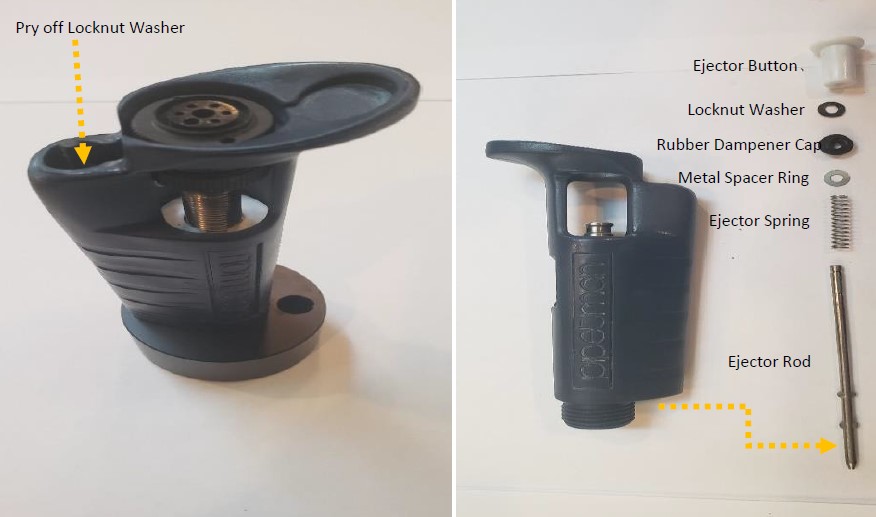
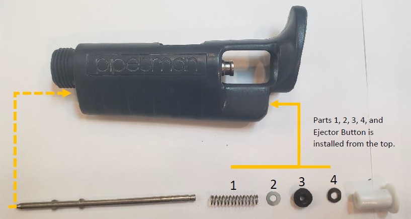
With a small-bladed flat head screwdriver, pry off the lock nut washer from the push rod ejector assembly. It may become damaged and will need to be replaced. Slide and remove all the ejector rod components from the bottom of the pipette body, as shown below.
NOTE: Based on the era of your Pipetman, some components may look slightly different.
Step 5:
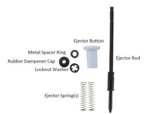
Based on the era of your Pipetman, the replacement push rod ejector assembly part number is likely GI F144872 and contains the parts as shown in the picture below.
Step 6:
Place the replacement locknut washer onto the clip removal (locking ring) tool.
Step 7:
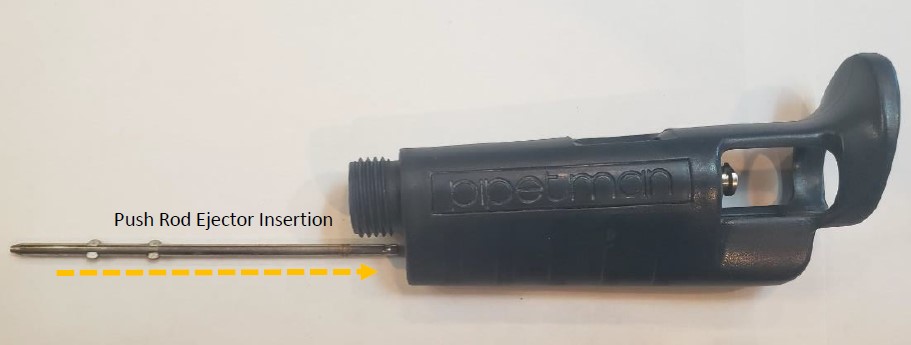
Fully Insert and hold the metal ejector rod assembly back into the pipette body through the bottom opening.
Step 8:
With the ejector rod inserted and held inside the body, place the pipette body onto the base holder as shown in the picture to the right. If done correctly, you will see the top of the ejector rod assembly sticking slightly out of the top of the pipette.
NOTE: Keep the small circular hole opening on the right side of the base and away from the ejector rod assembly for this process.
Step 9:
Install the replacement push rod ejector components onto the top portion of the push rod assembly in the order as shown in the picture below.
NOTE: #4 locknut washer will be installed onto the clip removal (locking ring) tool for installation.
Step 10:
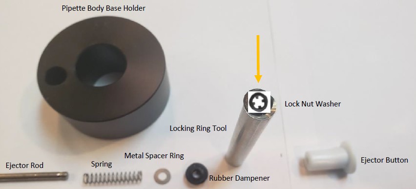
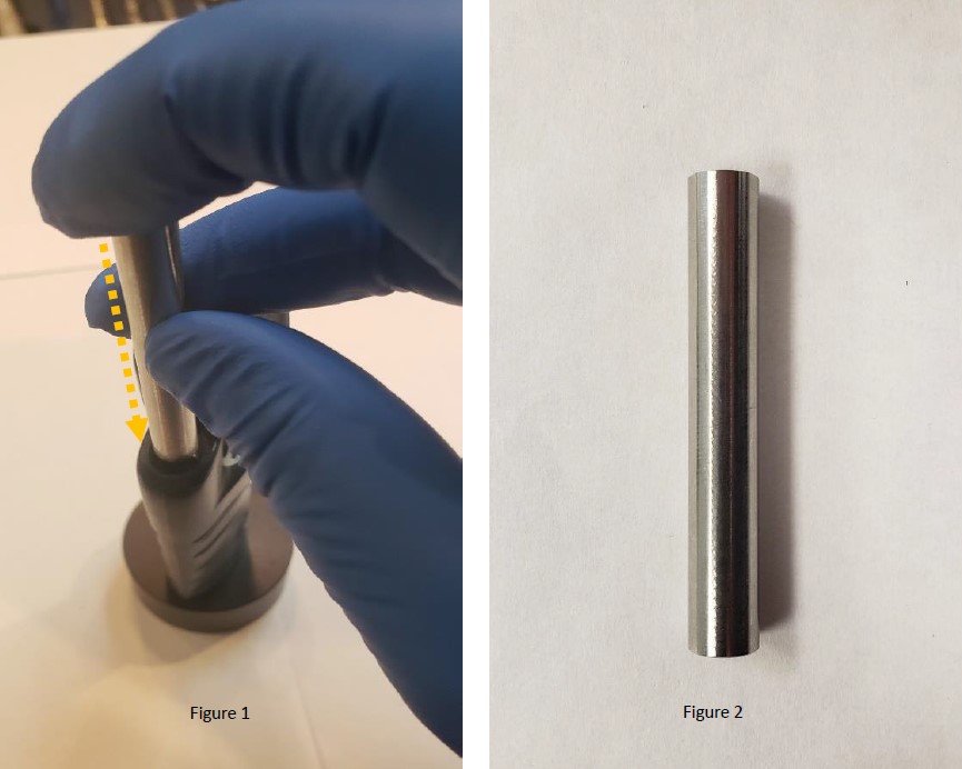
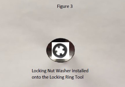
With the ejector rod inserted through the bottom of the pipette, and the spring, metal spacer ring, and rubber dampener inserted through the top of the pipette, place the locknut washer onto the locking ring tool. Figure 3.
Step 11:
As shown in figure 1, insert the clip removal (locking ring) tool face down into the push rod ejector rod, push the tool down to seat, and lock the locking ring onto the push rod ejector rod. If needed, tap the end of the locking ring tool with a rubber mallet to seat the locking ring into place. Remove the tool.
Step 12:
Install the tip ejector button back onto the ejector rod. Tap with a rubber mallet if needed.
Step 13:
Install the shaft and internal piston assembly back into the pipette body. Reattach the tip ejector arm to the pipette body. Test and recheck work if needed.
Disclaimer: Any action you take using the information on this website is strictly at your own risk. The information herein does not constitute professional advice and is general in nature. We make no warranty that this information will meet your requirements, be safe, accurate, or error-free. Pipette Supplies, Inc. is not responsible for any errors or omissions, any results obtained from the use of this information, or any loss or damage arising out of the use of this information. This site is for educational purposes only. Fair Use: Copyright Disclaimer under section 107 of the Copyright Act of 1976, allows for “fair use” for purposes such as comments, criticism, teaching, scholarship, news reporting, and research. Fair use is permitted by copyright statute that might otherwise be infringing.
The process of removing, replacing, and reinstalling the Rainin Push Rod Ejector Assembly requires great care, a high attention to detail, patience, and steady hands. Please dedicate a good work area with good lighting and space where small parts can be located should they pop/fly out during disassembly. Pipette damage and lost parts may occur if attention to detail is not maintained. Please proceed at your own risk.
These instructions are applicable for the following pipettes (single and multichannel):
Pipet-Lite (NOT APPLICABLE FOR PIPET-LITE XLS/XLS+. For Pipet-Lite XLS instructions, click here) (Ejector button not sold by Pipette Supplies)
Pipet-Plus (Different ejector button, not sold by Pipette Supplies)
EDP1 (Different ejector button, not sold by Pipette Supplies)
EDP3 (Different ejector button, not sold by Pipette Supplies)
RAININ Classic (Different ejector button, not sold by Pipette Supplies)
Recommended Service Tools
The following tools pictured here are strongly recommended to properly service, repair, or replace the Rainin push rod ejector assembly and/or the internal volume assembly.
Needle Nose Pliers
Bent Nosed Pliers: PS 10007 (Only required if completing the optional counter assembly replacement instructions)
Pipette Supplies does not current sell replacement Rainin Pipet-Lite (NON-XLS) Push Rod Ejector Assemblies.
Rainin Push Rod Ejector Disassembly Instructions
Step 1:
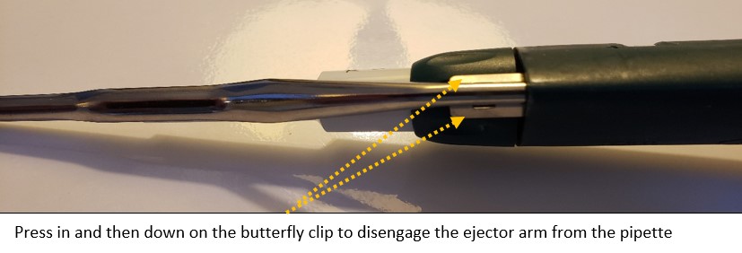
Remove the tip ejector arm from the pipette by pressing in and down on the butterfly clips. Once removed, lay the tip ejector arm aside for reassembly later.
Step 2:
Unscrew the shaft coupling nut. Remove the shaft and internal piston assembly.
CAUTION: Be careful when unscrewing the coupling nut. The piston spring is under tension and may fly out with the piston assembly parts.
Lay the piston assembly, shaft, and shaft coupling nut next to the tip ejector arm for reassembly later.
Step 3:
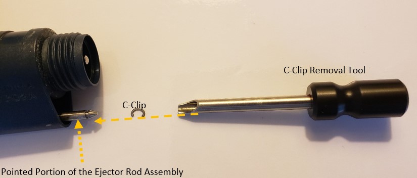
Locate the C-Clip removal tool. The C-Clip is the part that will be removed by the removal tool in step 4. Be careful to not lose the c-clip when removed, it can easily fly out of the pipette.
Step 4:
Press and hold down the tip ejector button to partially expose the pointed portion of the push rod assembly from the pipette body.
Step 5:
Fully insert the c-clip removal tool into the pointed portion of the push rod ejector assembly.
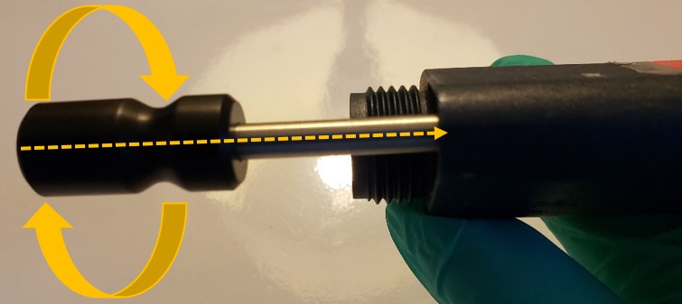
Step 6:
Once the c-clip removal tool is fully inserted into the Rainin push rod ejector assembly, twist the c-clip removal tool handle to dislodge the c-clip from the push rod ejector assembly. Begin by turning gently and then gradually apply more pressure as needed.
Note: Be prepared to lose the c-clip. Replace the c-clip as needed.
Step 7:
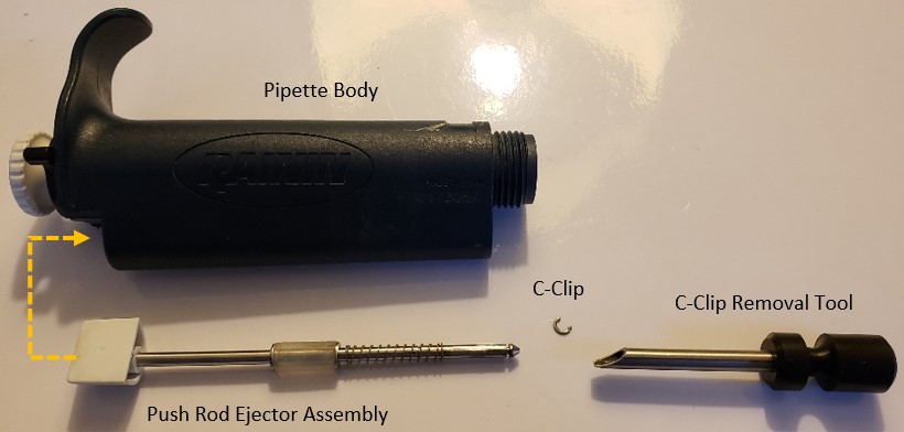
With the c-clip removed from the push rod ejector assembly, slide the push rod ejector upward to remove it from the top of the pipette body.
Step 8:
Examine the Rainin push rod ejector assembly components with a special emphasis on the grooved indentation on the push rod.
Note: The grooved indentation is the location where the c-clip will attach to during reassembly. The c-clip provides tension to the ejector spring, as well as keep the push rod ejector assembly in the pipette body.
With the needle-nosed pliers, gently grab and hold a c-clip as shown below.
Step 10:
Insert the c-clip into the grooved indentation on the c-clip installation tool, as shown below.
Step 11:
Notice the c-clip inserted into the grooved indentation on the c-clip installation tool.
Step 12:
Push and hold the ejector button. Gently slide the installation tool fully into the pointed end of push rod ejector rod assembly until the c-clip catches with the c-clip grooved indentation on the push rod ejector assembly. Shown in the picture on step 8.
Step 13:
Push the c-clip tool upward until you hear a slight click of the c-clip snapping back into place.
Step 14:
Insert the piston assembly back into the shaft and screw the shaft coupling nut back onto the pipette body.
Step 15:
Reattach the tip ejector arm back onto the pipette body.
Disclaimer: Any action you take using the information on this website is strictly at your own risk. The information herein does not constitute professional advice and is general in nature. We make no warranty that this information will meet your requirements, be safe, accurate, or error-free. Pipette Supplies, Inc. is not responsible for any errors or omissions, any results obtained from the use of this information, or any loss or damage arising out of the use of this information. This site is for educational purposes only. Fair Use: Copyright Disclaimer under section 107 of the Copyright Act of 1976, allows for “fair use” for purposes such as comments, criticism, teaching, scholarship, news reporting, and research. Fair use is permitted by copyright statute that might otherwise be infringing.
NOTE: These instructions are not recommended for the Pipetman L.You can find Pipetman L Counter Assembly instructions here.
Disassembly
Step 1:
Press and hold down the white colored tip ejector button. This will slightly lower the stainless-steel tip ejector arm and make it easier to remove. With a little force, carefully pull down on the tip ejector arm to detach and remove it from the pipette body. Lay aside for reassembly later.
Step 2:
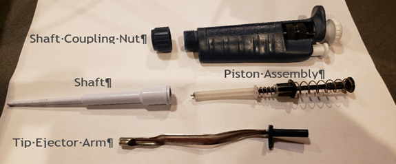
Carefully unscrew the shaft coupling nut from the pipette body.
CAUTION: When the shaft coupling nut is removed from the pipette body, the internal piston assembly might forcefully pop out from inside the white colored shaft. Take great care so the internal piston assembly and components do not pop and fly out of the shaft, or you may be forced to locate and or replace the seal, O-ring, seal retainer, stroke spring, blowout spring, or piston, if lost. Internal piston assembly components may vary slightly based on pipette nominal volume size. Lay aside for later.
Step 3:
Turn the to adjust the pipette plunger button and volume display to nominal volume (i.e., 100% of the pipette volume)
Step 3A:
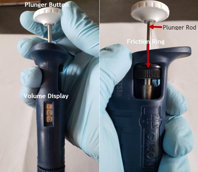
Then gently rotate the volume increasingly past nominal volume until the plunger button and volume display will not rotate further. STOP and do not force the volume turning further. Usually this occurs when the friction ring contacts the top portion of the pipette body.
Step 3B:
Remove the plunger button from the pipette by pulling upward and away from the plunger rod. Lay aside for later.
Step 4:
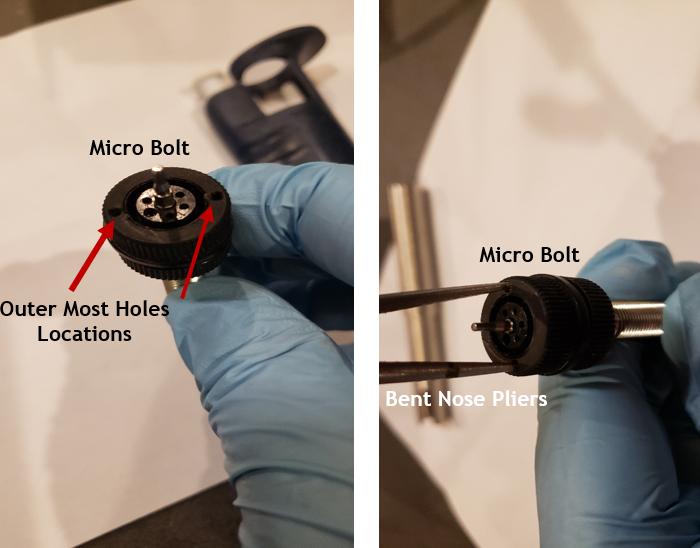
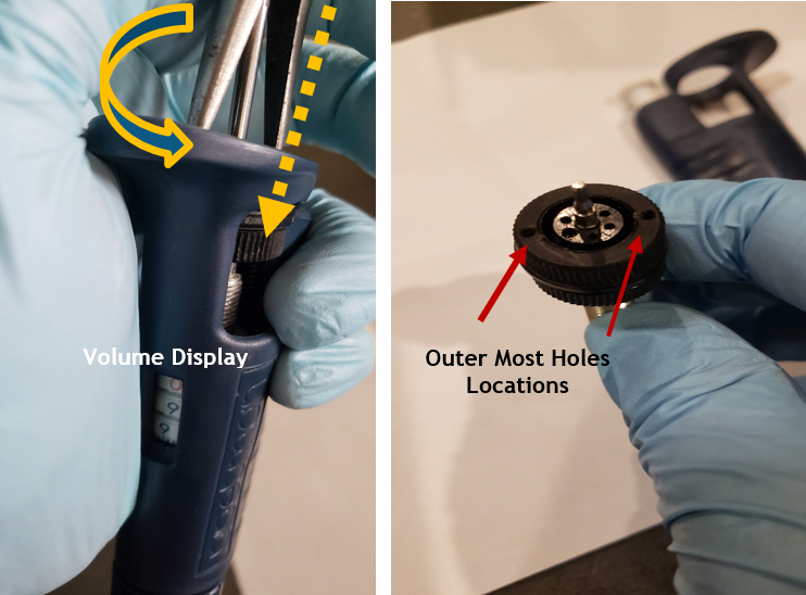
Insert bent nose pliers into the two outer most holes on the black colored micro bolt and continue to rotate the micro bolt in an increasing manner until it can be removed and pulled out from the pipette body. Lay aside for reassembly later.
NOTE: the bent nose pliers will provide the extra torque needed to allow the micro bolt and friction ring to be removed from the pipette body.
COMMENT: If desired, you may cut off the plastic or rubber friction ring from the micro bolt with a razor blade prior to Step 3A. This means you will need to replace the friction ring with a new one, prior to reassembly. If the friction ring is not cracked or brittle, replacement is usually not needed.
Photo Comments (below): The micro bolt was already removed from the pipette body to show the outer most holes easier for viewing purposes.
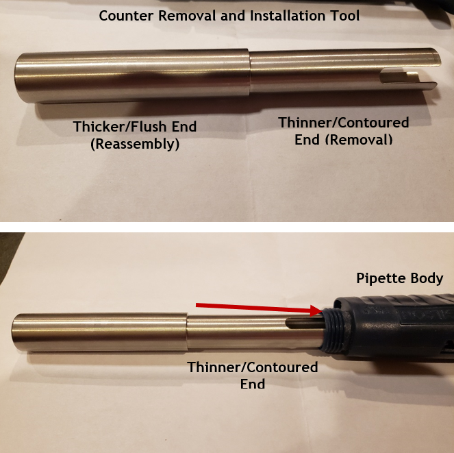
Counter Removal Tool Illustration (PS 10002): Shown to identify each end for intended use during removal and installation
Step 5:
Insert the slightly thinner and contoured end of the counter removal tool into the pipette body opening.
CAUTION: if the counter removal tool does not insert easily into the body opening and feels like it is being forced into the body, stop! Please do not force the tool into the body or it may get stuck, damage the pipette body, and require excessive force to remove the tool. Based on the age of the pipette, there is a possibility that the body opening may have shrunk slightly due to properties of the materials, environmental, age of the instrument, etc.
Step 6:
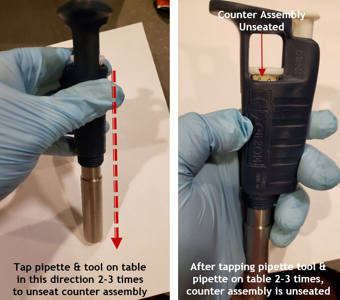
With the thinner contoured end fully inserted into the pipette body opening, gently tap or bang the end of the counter removal tool vertically onto a hard surface such as a table or bench top 2-3 times to unseat the counter assembly from the pipette body. This should be done vertically as shown.
Step 7:
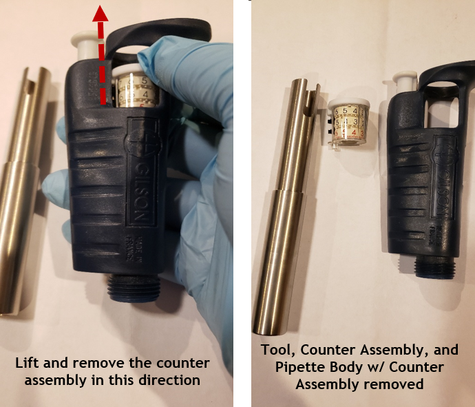
Remove the counter assembly tool from the pipette body and lay aside. Then, lift and remove the counter assembly out of the top of the pipette body.
New Counter Assembly, Installation, and Pipette Reassembly
Step 8 REASSEMBLY:
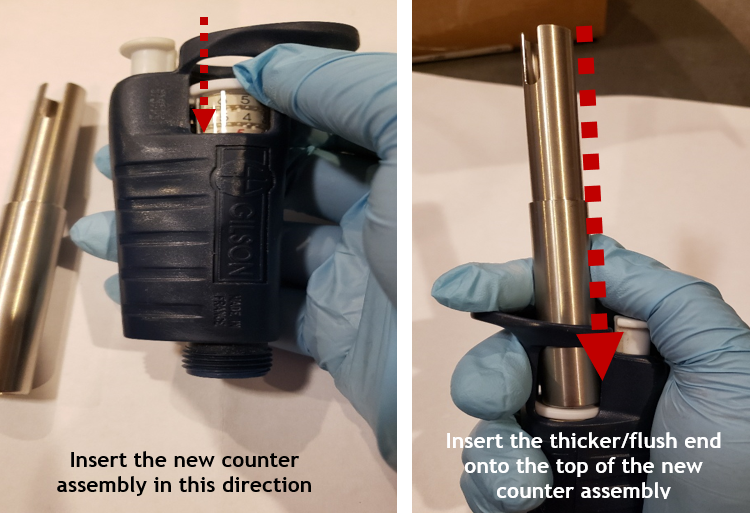
Carefully align and gently insert the new counter assembly into the top of the pipette body.
Step 8A:
Insert the thicker/flush end of the counter assembly tool on top of the new counter assembly and gently push the new counter assembly until it is seated properly and fully into the pipette body. Once the counter assembly is properly seated, remove the counter assembly tool.
Step 9:
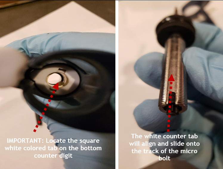
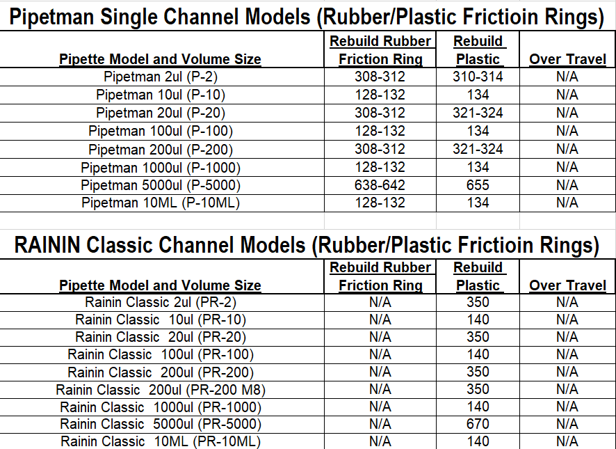
Refer to Appendix 1 and obtain the proper counter assembly digits needed for insertion of the micro bolt assembly back into the pipette body based on the nominal size of the pipette (i.e., 200uL, 1000uL, etc.). Loosely insert the micro bolt into the counter assembly and gently rotate until the desired counter assembly digits appear in the volume display window.
IMPORTANT: DO NOT ALLOW the micro bolt to seat into the pipette body until the desired digits are visible in the volume display window. This can be achieved by rotating the micro bolt and lifting it back out of the pipette and re-inserting it until the desired volume digits are visible in the volume display window.
Example: If the desired digits are 134 for a 1000uL pipette, loosely insert the micro bolt, rotate the micro bolt without it catching in the body, and remove/repeat until the micro bolt displays 134 in the volume display window.
Step 10:
Align the micro bolt assembly with the white colored notched tab on the counter assembly. Once aligned, insert and push the micro bolt into the body fully until it stops/seated.
Step 11:
Insert the bent nosed pliers into the two outer most holes on the micro-bolt.
Step 11A:
After insertion, press down and maintain force while turning the bent nosed pliers to seat the counter assembly fully back into the pipette body. Provide sufficient torque to allow the friction ring to seat back in place.
Step 11B:
When rotating the bent nosed pliers, the volume display digits will decrease as the micro bolt is seated back into place. Continue until the friction ring is below the top portion of the pipette body and the micro bolt can be rotated by hand and no longer with the pliers.
Step 11C:
Wind the pipette to the 10% volume.
Step 12:
Insert the piston assembly back into the shaft and place the coupling nut back on the shaft. Fully screw the shaft coupling nut back onto the pipette body.
Step 13:
Press down on the tip ejector button and reattach the tip ejector arm to the pipette body.
Step 14:
Verify the desired accuracy and precision of the pipette is obtained on an appropriate balance. Calibration adjustments may be needed.
Disclaimer: Any action you take using the information on this website is strictly at your own risk. The information herein does not constitute professional advice and is general in nature. We make no warranty that this information will meet your requirements, be safe, accurate, or error-free. Pipette Supplies, Inc. is not responsible for any errors or omissions, any results obtained from the use of this information, or any loss or damage arising out of the use of this information. This site is for educational purposes only. Fair Use: Copyright Disclaimer under section 107 of the Copyright Act of 1976, allows for “fair use” for purposes such as comments, criticism, teaching, scholarship, news reporting, and research. Fair use is permitted by copyright statute that might otherwise be infringing.
How to Replace the Volume Catch on an Eppendorf Reference 2 Pipette
The process of replacing the left and right-side volume catch, internal springs, and tab levers is a careful process that could damage the pipette if attention to detail is not maintained. Volume catch replacement requires a high level of patience and steady hands. Please dedicate a good work area with good lighting and space where small parts can be located should they pop/fly out during disassembly. Please proceed at your own risk.
Equipment and Supplies Needed:
Eppendorf Reference 2 Pipette
A primary small-bladed tool such as a flat-head screwdriver
A secondary small-bladed tool such as a flat-head screwdriver (as a back-up if needed)
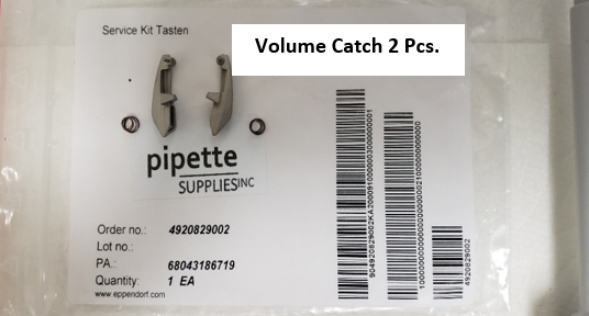
Volume Catch replacement parts, 2 pcs, Part # EP 4920829002
Step 1:
Verify and ensure that you have the PipetteSupplies.com Reference 2 Volume Catch replacement parts, 2 pcs, Part # EP 4920829002.
A set of two (2) volume tabs
A set of two (2) springs
Step 2:
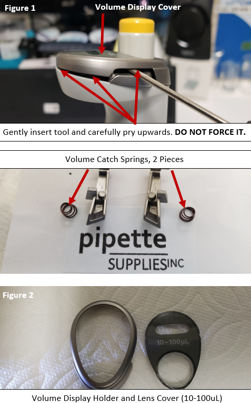
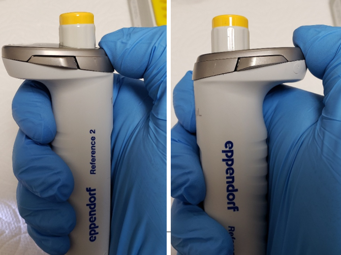
With the small-bladed tool, very carefully and very gently, insert the tool into the left side catch lever, as shown in figure 1.
Gently pry the volume display cover up. DO NOT force it.
Remove and re-insert your small-bladed tool in the right side catch lever and gently pry up. DO NOT force it.
CAUTION: When prying up the volume display cover, be aware that the volume catch springs may pop off and fly out of the pipette when the cover is removed.
Remove and re-insert your small-bladed tool into different areas just underneath the volume display cover and gently pry upward.
Keep repeating gently, as you would to pry off the lid on a can of paint, until the volume display cover comes off. As shown in figure 2.
Step 3:
With the display cover removed, locate and lay aside the following parts:
Volume Display Holder
Lens Cover
Left Volume Catch & Spring
Right Volume Catch & Spring
Step 4:
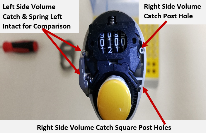
With the right-side volume catch & spring removed, notice the volume catch post hole that the volume catch will sit in when reassembled.
Secondly, notice the two (2) somewhat square post holes that the other end of the volume catch will sit on and spring location/position.
Double check all work. Ensure all parts are accounted for and/or new parts are available for installation before progressing to reassembly.
Observations of New Volume Catch & Preparations for Reassembly
Step 5:
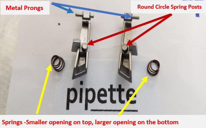
Inspect your new replacement volume catch and pay special attention to the following:
Springs – smaller end and larger end (if applicable)
Round circle spring post mounts on the volume catch
The metal prongs protruding from the top of the volume catch.
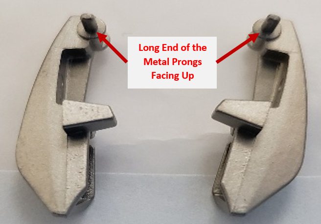
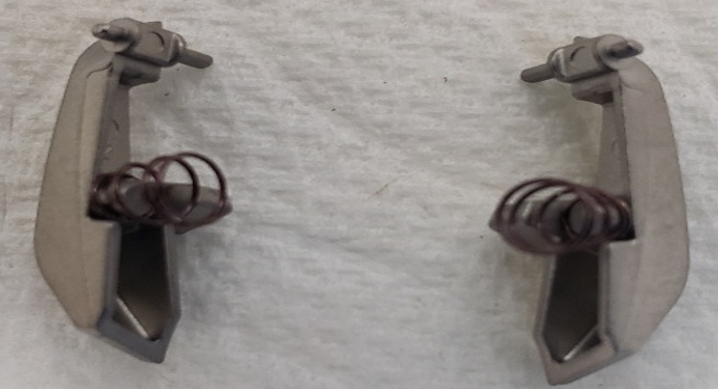
Observation 1:
The volume catches pictured here are positioned in the orientation of how they would look if you were looking up from inside the counter assembly. Notice the metal prongs have the short end of the post facing down and the longer end of the metal post is facing up.
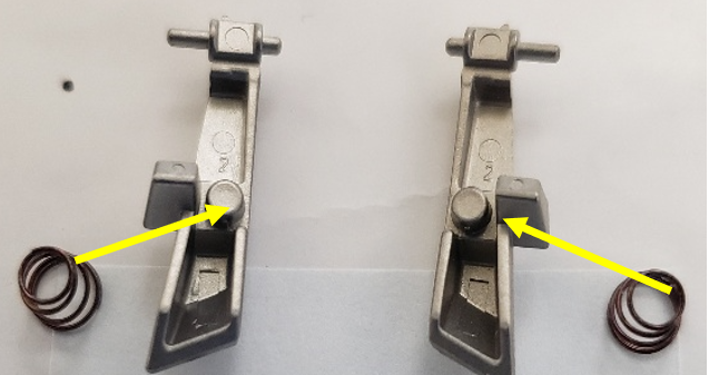
Observation 2:
The volume catches pictured below are rotated with the underneath side facing up. Practice installing the small end of the spring onto the round circle spring posts. Note: Be aware during installation of the volume catch onto the pipette. The spring(s) my pop or fly off a few times until you masterthe installation process. Maintain keen eyes during this process.
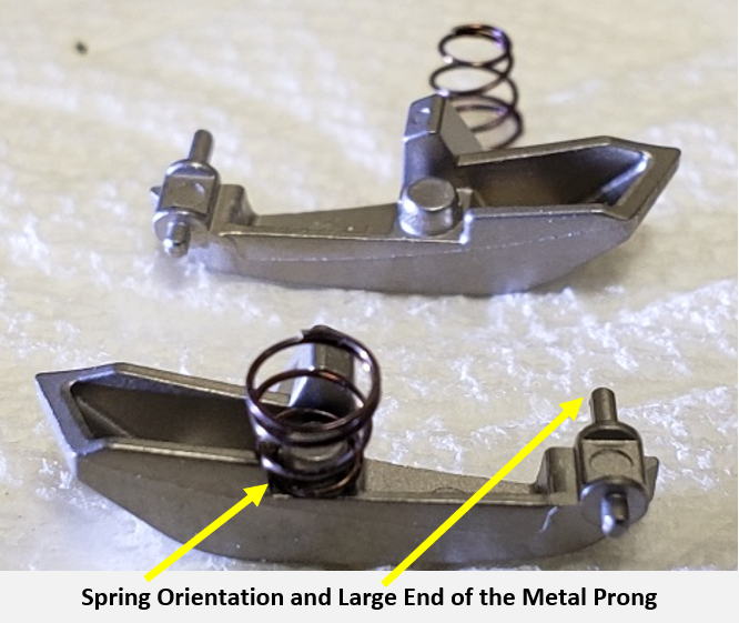
Observation 3:
Close-up photo of the spring installed onto the volume catch. The other spring is positioned small side up for better visualization.
Notice the orientation of the longer end of the metal prong. This is the portion that is installed into the pipette body
The shorter prong is what is attached to the volume display cover.
Observation 4:
Close-up photo of the springs installed onto the volume catch. The small end of the spring is installed first.
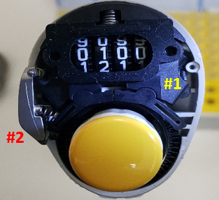
Observation 5:
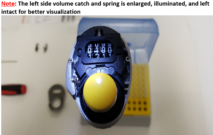
Enlarged photo of the right-side volume catch removed. (#1 below)
Left Side volume catch already installed for better visualization. (#2 below)
Volume Catch Installation and Re-Assembly
Step 6:
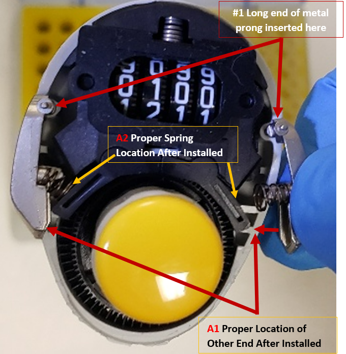
With the small end of the spring already inserted onto the volume catch:
(1) Insert the long end of the metal prong into the round hole in the pipette body, as shown.
(2) Place the other end of the volume catch on top of the square holes, A1 until secure.
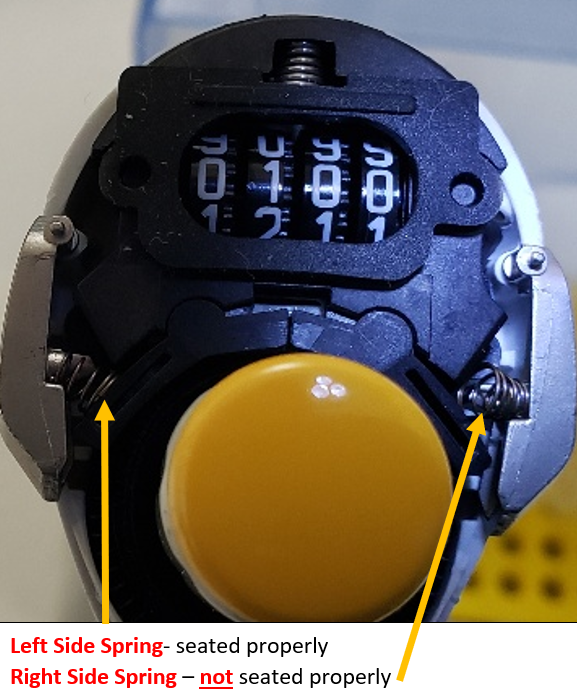
Note: When the lower end of the volume catch is properly installed, the spring will now be resting against “A2” and will be under tension. Do not bump or it will fly off and you will need to repeat the process.
This is the most tedious process and make take 3-5 times before mastered and the volume catch is properly installed.
Step 7:
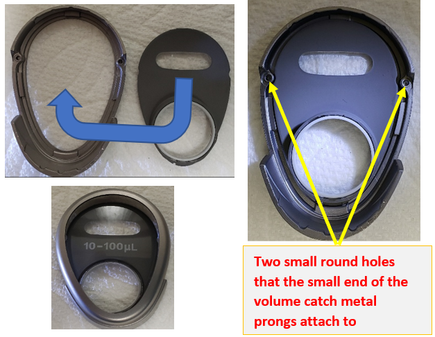
Insert the lens cover into the volume display holder.
Notice the two small round holes on the inside of the volume display holder. These are the posts that the short end of the metal prongs of the volume catch insert into when the volume display cover is installed back onto the pipette.
Step 8:
Double check that the volume catch and springs are still properly seated and in place, as shown here. If YES got to Step 9. If NO, re-install properly.
Step 9:
Once the volume catch and springs are properly positioned, install the volume display cover back onto the Reference 2 pipette until it snaps in place. Ensure there are no gaps, and that everything is snug.
Test the levers by pushing in on them and adjusting the volume. Recheck work as necessary. In some cases, calibration of the pipette may be required to ensure accuracy and precision is maintained.
Disclaimer: Any action you take using the information on this website is strictly at your own risk. The information herein does not constitute professional advice and is general in nature. We make no warranty that this information will meet your requirements, be safe, accurate, or error-free. Pipette Supplies, Inc. is not responsible for any errors or omissions, any results obtained from the use of this information, or any loss or damage arising out of the use of this information. This site is for educational purposes only. Fair Use: Copyright Disclaimer under section 107 of the Copyright Act of 1976, allows for “fair use” for purposes such as comments, criticism, teaching, scholarship, news reporting, and research. Fair use is permitted by copyright statute that might otherwise be infringing.