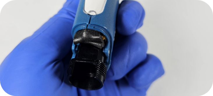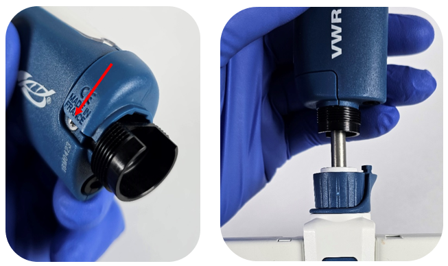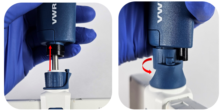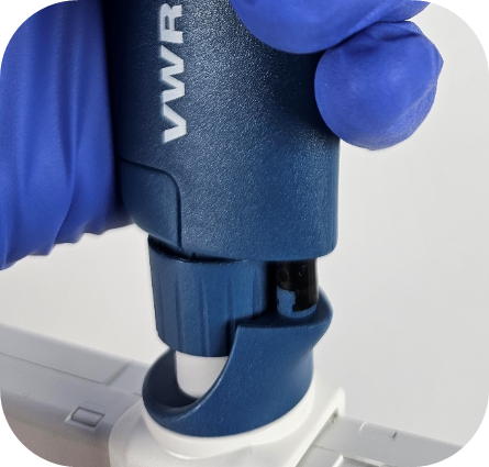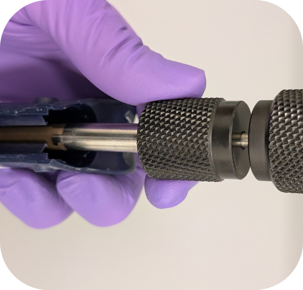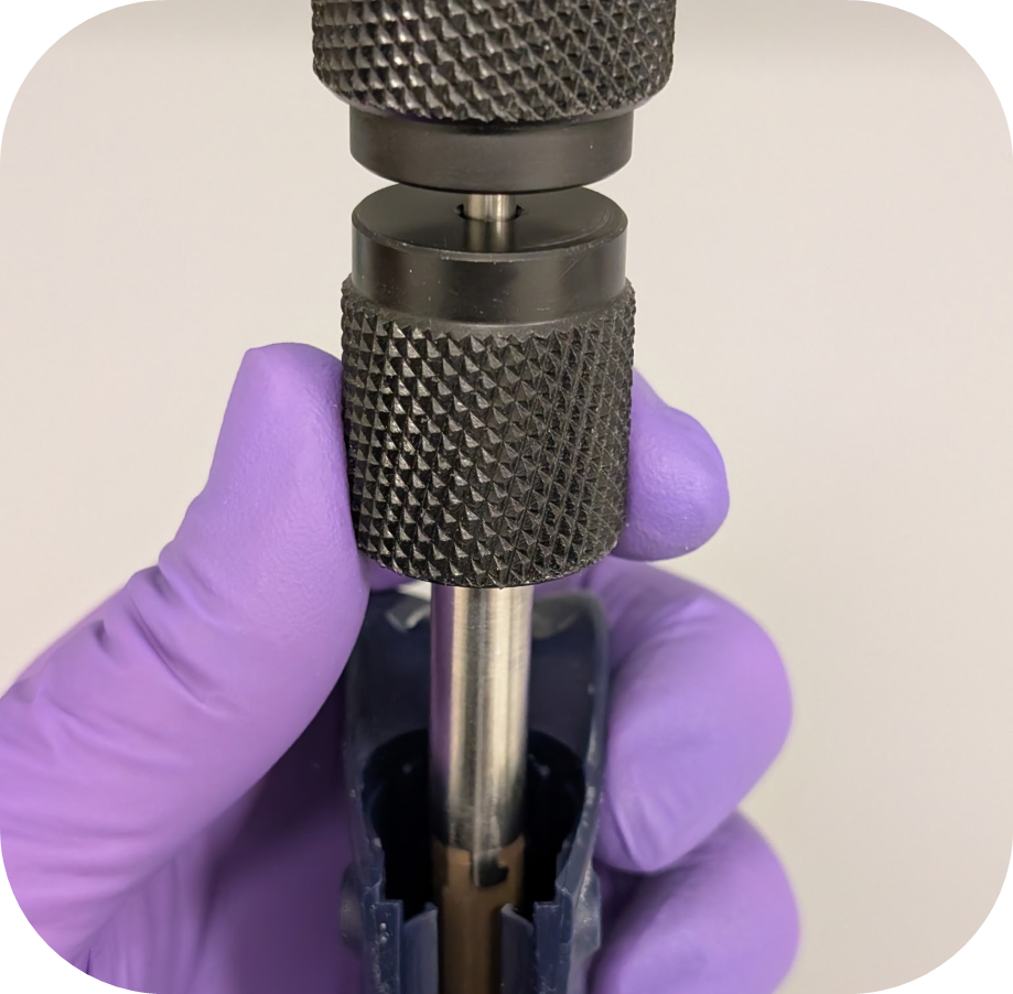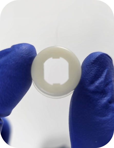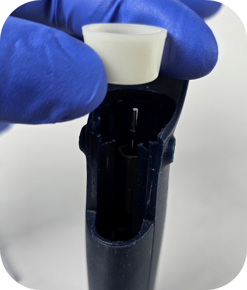
Author: Pipette Supplies Team

  • Sartorius / Biohit mLINE, eLINE, Proline Plus, Tacta, Picus, and Picus NxT Single Channel Pipette – Piston Replacement

    The process of removing, replacing, and reinstalling the piston assembly for the Biohit/Sartorius mLINE, eLINE, Proline Plus, Tacta, Picus, and Picus NxT single channel pipettes requires great care, a high attention to detail, patience, and steady hands. Please dedicate a good work area with good lighting and space where small parts can be located should they pop/fly out during disassembly. Pipette damage and lost parts may occur if attention to detail is not maintained. Please proceed at your own risk.

    Replacement Parts:
    1. Pistons
    2. Replacement Seals

    Note: Not all seals are available, but they can be purchased with the full lower assembly or the individual pistons.

    Recommend Supplies:
    1. Gloves
    2. KimWipes
    3. Coated Needle Nose Pliers(non-marring)

    Preliminary Note:
    This disassembly process applies to the single-channel variants of each listed model. It is also recommended to inspect and replace the seal and any damaged components of the lower assembly during this procedure.

    Step 1:

    Adjust the pipette to its lowest volume setting. This allows for easier removal and installation of the piston.
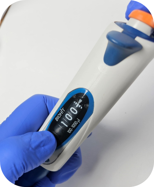
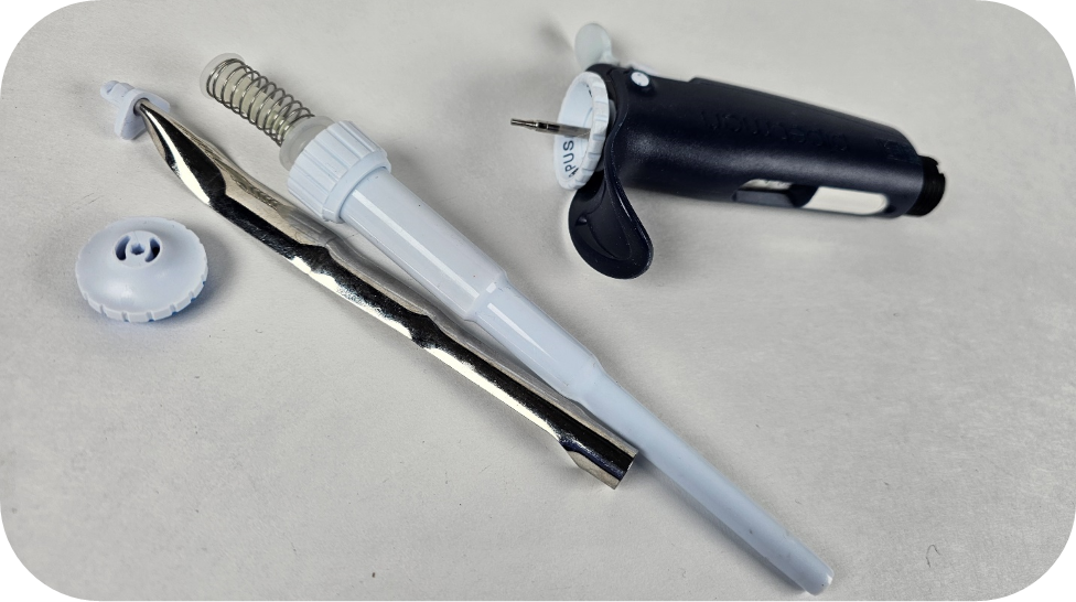
    Biohit pipette
    Step 2:

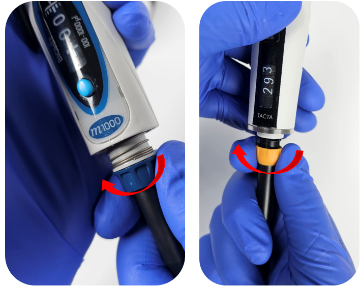
    Unscrew the tip ejector sleeve in a counter-clockwise direction from the lower half of the pipette body.

    Note: When removing the tip ejector for the Tacta, make sure to unscrew the ejector on the beveled edge below the silver ring on the body of the pipette.
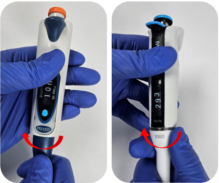
    Remove the tip cone
    Step 3:

    Unscrew the connecting nut counter-clockwise from the tip cone.
    Once disengaged, gently pull down on the tip cone to remove it from the pipette.
    removing piston
    Step 4:

    To remove the piston, use a pair of coated needle-nose pliers to grip the operating rod.

    Note: Use pliers with a rubber or plastic coating to prevent damage to the plastic operating rod. If coated pliers are unavailable, wrap two layers of a nitrile glove around the operating rod to minimize the risk of damage while using pliers.
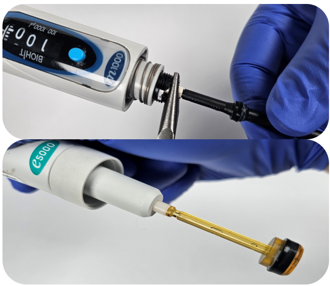
    removing the Sartorius piston
    Step 5:

    While holding the operating rod with the pliers, rotate the piston counter-clockwise to loosen it. The piston is usually hand-tightened, but you may need an extra set of coated pliers to remove it.
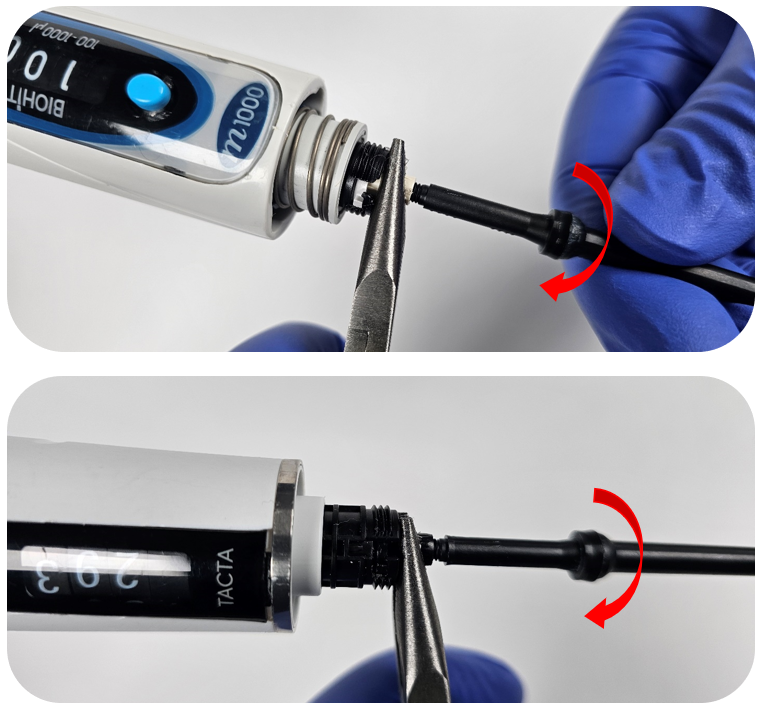
    rotating the sartorius piston
    Step 6:

    Inspect the seal before reassembly. If it appears cracked, deformed, or worn, it should be replaced.
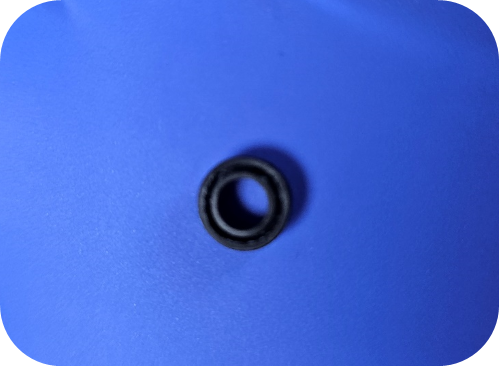
    Sartorius piston seal
    Step 7:

    Install the new Sartorius piston by threading the threaded end into the operating rod clockwise.
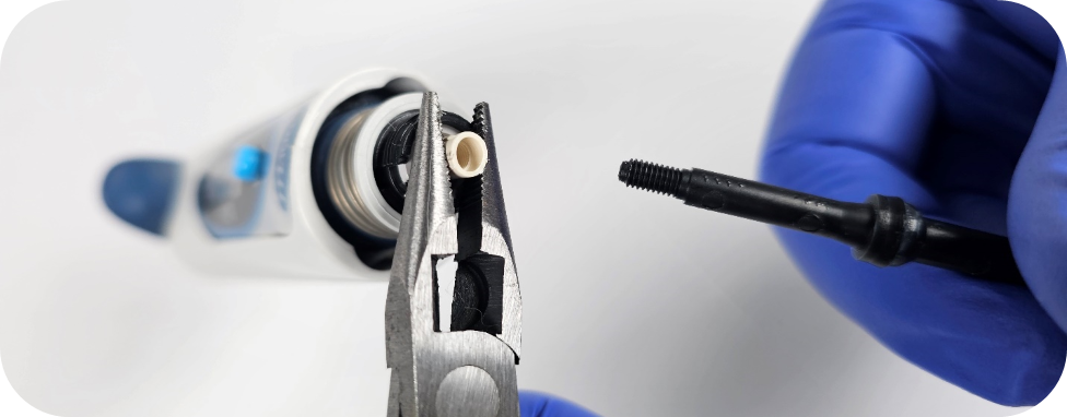
    Reinstalling the piston

    After tightening by hand, an additional pair of coated needle-nose pliers can be used to snug up the piston if needed.

    Caution: Do not overtighten. Overtightening may cause damage to the threaded operating rod.
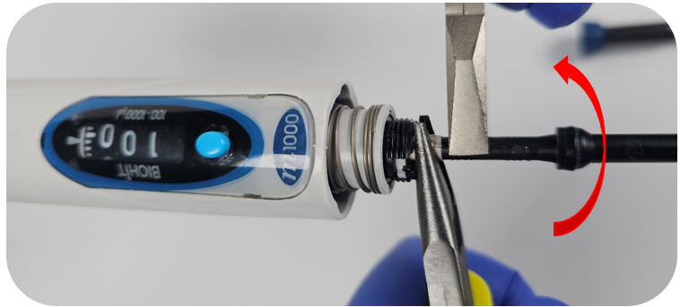
    turning the piston snug
    Step 8:

    After confirming the seal is in good condition, reattach the tip holder and secure it with the connecting nut.
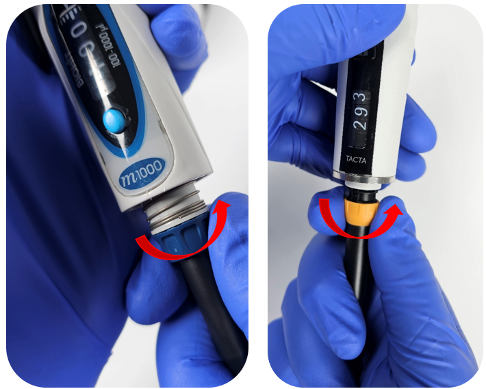
    reattaching the tip cone
    Step 9:

    Reattach the ejector sleeve by threading it back onto the ejector assembly.
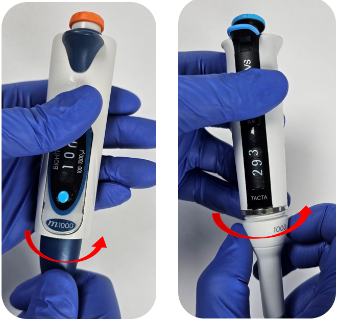
    Reassembling the ejector sleeve

    Step 10:

    After replacement of the piston, it is a good idea to check the pipette to ensure it is operating within manufacturers specifications.

    Disclaimer: Any action you take using the information on this website is strictly at your own risk. The information herein does not constitute professional advice and is general in nature. We make no warranty that this information will meet your requirements, be safe, accurate, or error-free. Pipette Supplies, Inc. is not responsible for any errors or omissions, any results obtained from the use of this information, or any loss or damage arising out of the use of this information. This site is for educational purposes only.
    Fair Use: Copyright Disclaimer under section 107 of the Copyright Act of 1976, allows for “fair use” for purposes such as comments, criticism, teaching, scholarship, news reporting, and research.
    Fair use is permitted by copyright statute that might otherwise be infringing.

    Related Posts:
    Sartorius Picus: Handle Assembly/Disassembly
    How to Adjust the Calibration for a Sartorius mLINE Single Channel Pipette
    How to Replace the Tip Ejector Mechanism on a Sartorius mLINE Single Channel Pipette
    Sartorius mLINE 5000uL Single Channel Piston Cleaning & Preventive Maintenance
    Replacing a Damaged or Missing Sartorius mLINE Volume Display Window
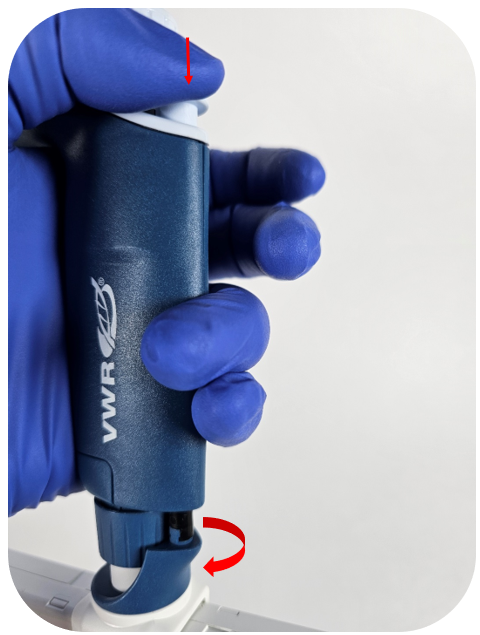
  • Gilson Pipetman M & VWR Electronic – Battery Replacement

    The process of removing, replacing, and reinstalling the battery for the Gilson Pipetman M & VWR Electronic(after market version of Pipetman M) requires great care, a high attention to detail, patience, and steady hands. Please dedicate a good work area with good lighting and space where small parts can be located should they pop/fly out during disassembly. Pipette damage and lost parts may occur if attention to detail is not maintained. Please proceed at your own risk.

    Replacement Parts:

    1. Batteries: Serial Number range specific
      • GI F807007 – For newer Pipetman M pipettes with serial numbers from GD14021 (battery batch code 10-2010 / 11-2010 or later)
      • GI F807113 – For older Pipetman M pipettes with serial numbers from DL80001 to GD14020 (battery batch code 08-2009 and 05-2010)
      • The VWR Electronic models utilize the same battery as the newer style battery (GI F807007).

    Recommend Supplies:

    1. Flat-Head Screwdriver
    2. Thin Needle nose pliers

    Preliminary note: This disassembly process applies to both single and multichannel models, as they have an identical upper half of the pipette and attach to the ejector assembly in the same fashion.

    Step #1:

    Start by pushing down on the Pipetman M / VWR Electronic ejector button and unclip the tip ejector from the ejector assembly.

    Pipetman M ejector removal
    Step #2:

    Unthread the connecting nut from the pipette body.

    connecting thread removal
    Step #3:

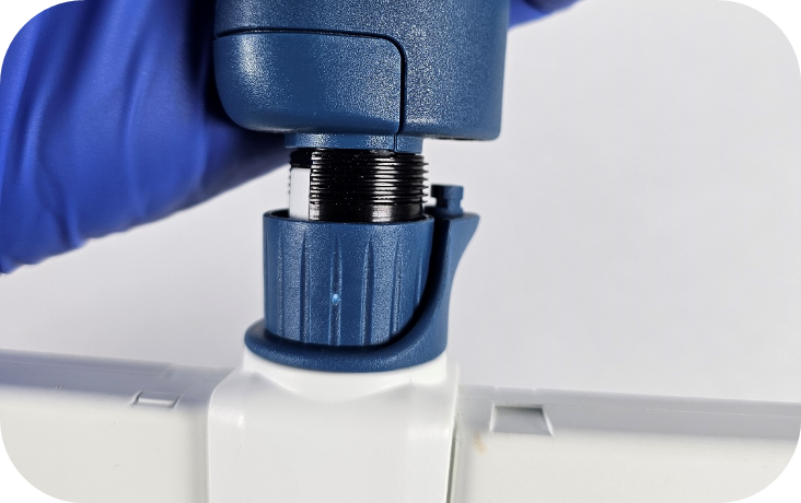
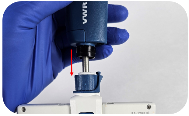
    Gently pull down on the lower assembly to disconnect the lower assembly from the upper handle.

    Note: The piston assemblies are magnetically attached to the spindle. In some cases —particularly with single channel models—the piston may not detach with the removal of the lower assembly. If this occurs, gently pull down on the piston assembly to remove it. To prevent damage, it is recommended to remove the piston/operating system before proceeding.

    removing Pipetman M / VWR Electronic lower part
    Step #4:

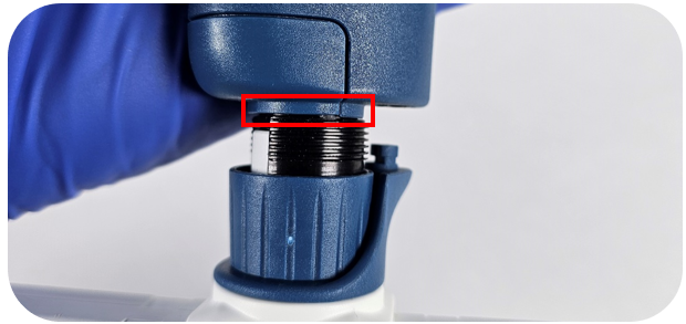
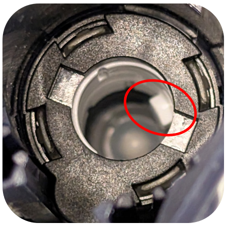
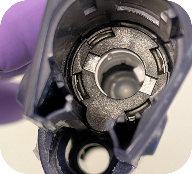
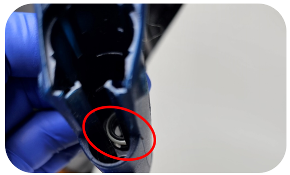
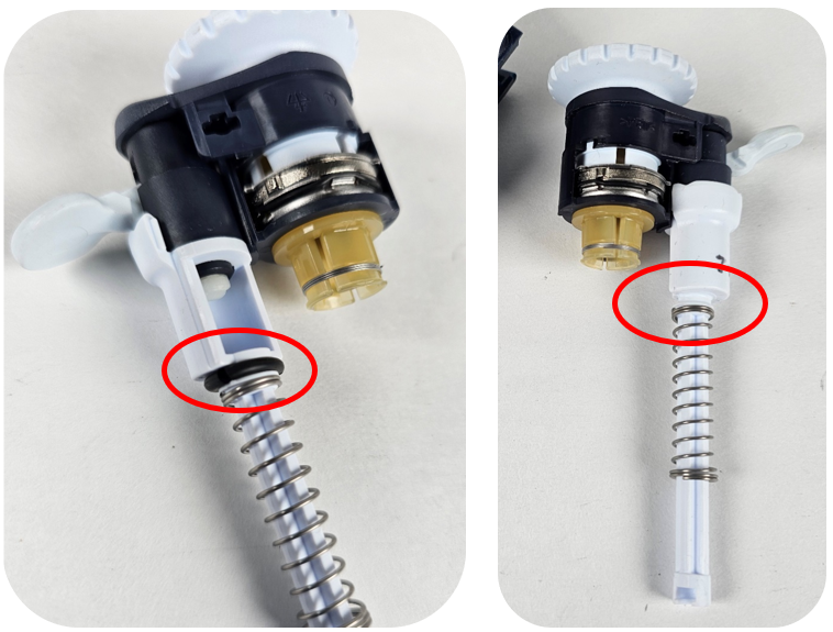
    Some Pipetman M / VWR Electronic multichannel models have an O-ring located above the threads on the pipette body (see picture below for reference). The O-ring tend to dry out and crack over time. It is recommended to remove the O-ring as part of this repair process.

    Note: Gilson does not replace these O-rings as part of their standard service.

    o-ring location (Pipetman M / VWR Electronic)
    Step #5:

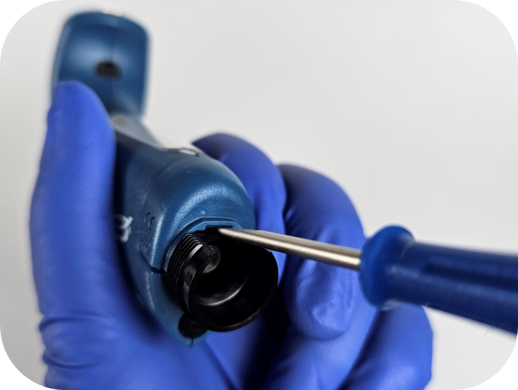
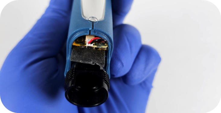
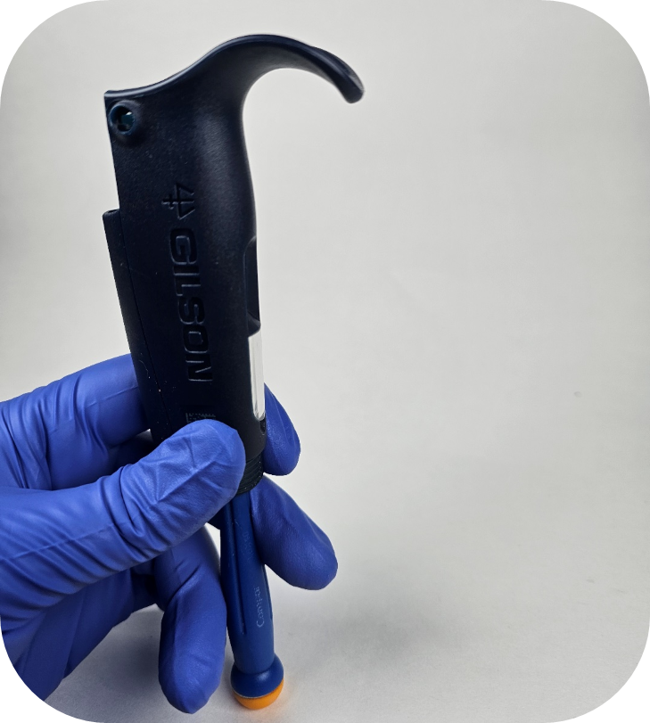
    Using the flat-head screwdriver, pry up the battery door on the bottom of the handle (see picture below for reference).

    removing battery door
    Step #6:

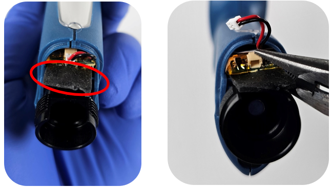
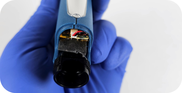
    Once the battery door is removed, carefully unplug the connector from the socket on the battery’s circuit board.

    Note: It’s a good idea to connect the new battery first to confirm it resolves the issue before attempting to remove the old battery, as the new battery could be damaged during removal.

    battery position in Pipetman M / VWR Electronic
    Step #7:

    After the plug is disconnected, locate the tab on the back of the battery and slowly pull the battery out of the compartment.

    Note: It’s common for the battery removal tab to break during this process. Needle-nose pliers can be helpful, as space in the battery compartment is limited. To remove the battery using pliers, position the two sides of the pliers around the socket on the circuit board and carefully pull the battery out.

    battery removal
    Step #8:

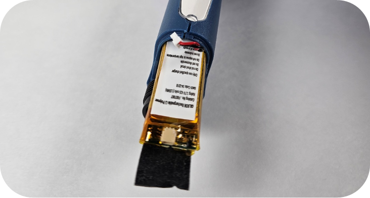
    Install the new battery, ensuring that the side with the tab and socket is oriented correctly. Refer to the image below for the proper orientation of the battery.

    battery orientation in the Pipetman M / VWR Electronic
    Step #9:

    Push the battery fully into the battery compartment, then reinsert the plug into the socket on the circuit board.

    battery secured
    Step #10:

    Before securing the battery door, make sure to lift the tab to ensure the door sits flat. In some cases, the flap can be tucked over the circuit board and into the top edge of the battery compartment, as shown in the image below.

    battery flap
    Step #11:

    Reattach the Pipetman M / VWR Electronic battery door, then reconnect the spindle to the piston (or to the operating system for multichannel pipettes).

    reassembling the Pipetman M / VWR Electronic
    Step# 12:

    Slowly push the lower assembly toward the pipette body/handle. Once it is fully seated, tighten the connecting nut securely around it.

    connecting the lower part
    Step# 13:

    Push down on the ejector button and reattach the tip ejector clip.

    Note: When reattaching the lower assemblies of single channel pipettes, leaks can occur. It is important to ensure that all lower assembly parts are tightly secured.

    reattach the tip ejector clip on the Pipetman M / VWR Electronic

    Disclaimer: Any action you take using the information on this website is strictly at your own risk. The information herein does not constitute professional advice and is general in nature. We make no warranty that this information will meet your requirements, be safe, accurate, or error-free. Pipette Supplies, Inc. is not responsible for any errors or omissions, any results obtained from the use of this information, or any loss or damage arising out of the use of this information. This site is for educational purposes only.
    Fair Use: Copyright Disclaimer under section 107 of the Copyright Act of 1976, allows for “fair use” for purposes such as comments, criticism, teaching, scholarship, news reporting, and research.
    Fair use is permitted by copyright statute that might otherwise be infringing.

  • Gilson Pipetman L – Counter Assembly Replacement

    The process of removing, replacing, and reinstalling the Gilson Pipetman L counter assembly requires great care, high attention to detail, patience, and steady hands. Please dedicate a work area with good lighting and space where small parts can be located should they pop/fly out during disassembly. Pipette damage and lost parts may occur if attention to detail is not maintained. Please proceed at your own risk.

    Replacement Parts:

    1. Cap Screws
    2. Counter Assemblies: Volume Specific
      • Pay special attention to the description as there are autoclavable and non-autoclavable parts in the counter link above. If a non-autoclavable counter is used in an autoclavable pipette, the counter will shrink around the adjustment screw if the pipette is autoclaved. The counter will become fused making it nearly impossible to disassemble/repair the pipette.
      • The autoclavable models can be identified by the following symbol on the pipette body:

    Recommend Supplies:

    1. Cap screw removal tool
    2. Pipetman L calibration tool
    3. Xacto Knife
    4. Needle nose pliers

    Preliminary note: It is recommended to use the Pipetman L-specific tools, as they make repairs easier. We will provide instructions for completing the counter replacement without these tools. Please note that improper execution can cause marring or damage to the pipette, as all parts are made of plastic.

    Step #1:

    Start by removing the lower assembly, tip ejector, and button from the operating rod.

    Note: If you do not have the Pipetman L calibration tool, it is recommended to adjust the pipette to the nominal volume prior to starting step #2.

    Pipetman L disassembled
    Step #2:

    While pushing down on the blue part of the lock/unlock assembly, use the cap screw removal tool to turn the cap screw counterclockwise a quarter turn.

    removing cap screws

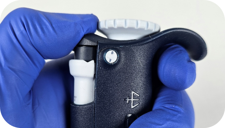
    Ensure the cap screws are in the unlocked position as it is easy to turn them too far. Make sure the two indents make a vertical line as seen below:

    removing cap screws

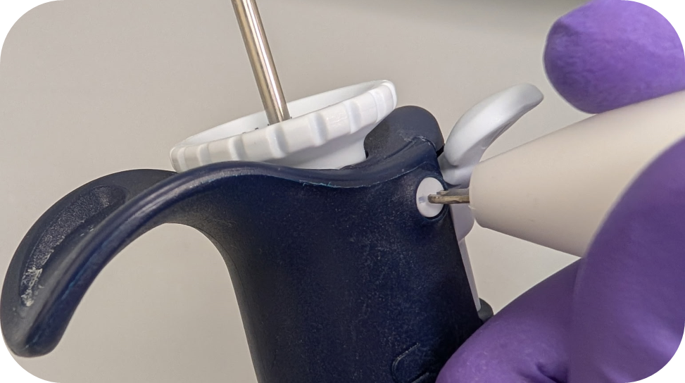
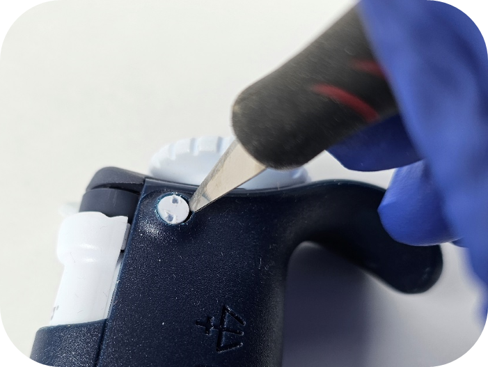
    Note: If you have trouble getting the cap screws out, an Xacto knife can be used to flick/pry the cap screw out of the hole.

    using xacto knife
    Step #3:

    The lock/unlock assembly should be easily removed by pulling up on the assembly.

    removing Pipetman L assembly
    Step #4:

    Now that the assembly is removed, invert the pipette. The bushing/collar around the adjustment screw should fall out.

    Pipetman L collar
    Step #5:

    Utilizing the Pipetman L calibration tool, secure the outer teeth of the tool to the flat sides of the adjustment screw.

    Note: If you do not have a calibration tool you can re-seat the lock/unlock assembly and adjust the pipette beyond the nominal volume until there is enough of the adjustment screw exposed to turn it with your fingers.

    Pipetman L calibration tool
    Step #6:

    Turn the Pipetman L calibration tool counterclockwise to remove the adjustment screw from the pipette. Once the adjustment screw disengages, pull the calibration tool straight out to remove the adjustment screw.

    Step #7:

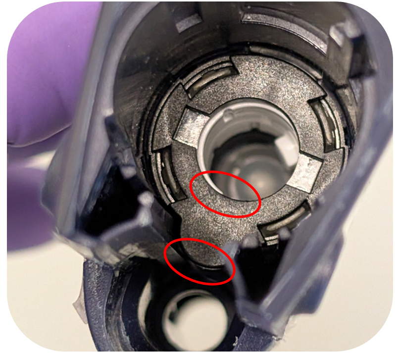
    To remove the Pipetman L counter, insert the needle nose pliers into the adjustment screw hole in the counter and on the side containing the counter gears (circled in red below). It is important to have thin needle nose pliers to ensure you only grab the counter and not the two fins on either side of the counter gear assembly.

    Note: The Gilson counter removal tool does not work for the Pipetman L and unfortunately, an updated tool is not available.

    placement for pliers

    If you’re having trouble removing the counter with needle-nose pliers, you can also try using a flat-head screwdriver. After removing the adjustment screw, insert the flat-head screwdriver from the bottom of the pipette and secure it against the bottom part of the tab, pictured below. Once the screwdriver is in place, we recommend looking through the top to ensure the screwdriver is properly seated on the bottom of the counter’s tab.

    bottom tab

    While holding the screwdriver in place, gently tap or push the handle end against a flat surface. This process may take a few attempts, as the screwdriver can slip off the plastic tab. Take extra care to avoid damaging the internal threads of the pipette body when performing this variation.

    tap the handle on flat surface
    Step #8:

    Install the new counter by applying downward pressure using your thumb or a screwdriver. A tactile click will confirm that the counter is properly seated.

    Pipetman L counter seating

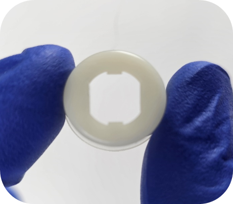
    Note: On the very early non-autoclavable models of the Pipetman L, the spacer (opaque white ring) below the counter was not secured in by plastic tabs. If you are working on this model, the spacer will seat once the counter is snapped into place. For the autoclavable models, the spacer stays in place and should not be removed.

    Pipetman L counter spacer
    Step #9:

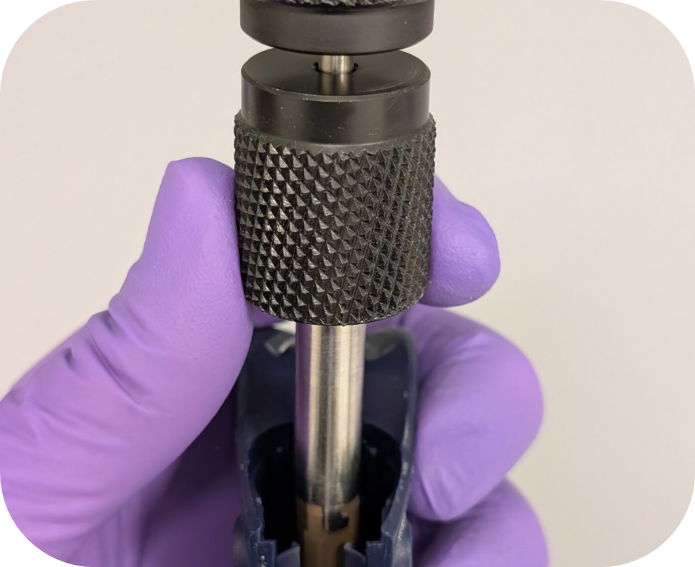
    Attach the adjustment screw to the calibration tool and line up the tooth in the counter with the channel in the adjustment screw. To ensure the correct index value is set, it is important to not engage the adjustment screw in the threads below the counter until step #10 is completed.

    Pipetman L calibration tool
    Step #10:

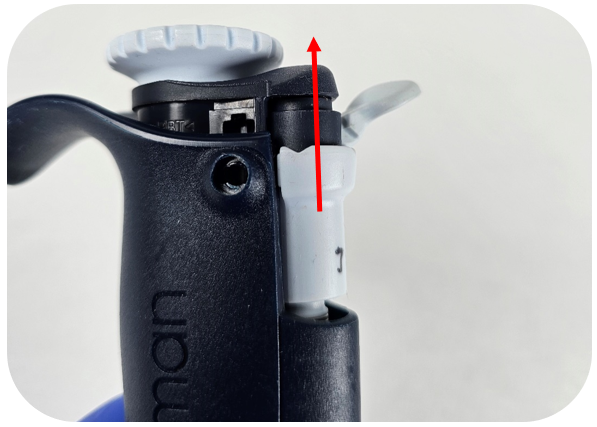
    Utilize the table below to set the index value of the Pipetman L counter. It is important to ensure the adjustment screw does not engage with the thread in body below the counter when setting the index.

    VolumesIndex Value
    10μL, 100μL, 1000μL, 10mL135
    2μL, 20μL, 200μL235
    5mL670
    Step #11:

    Once the counter reads the value listed above, apply firm downward pressure and turn the adjustment screw/calibration tool clockwise.

    adjusting
    Step# 12:

    Reinstall the spacer, paying special attention to the orientation (flared side faces up) and alignment of the grooves on the adjustment screw. The spacer will slide down the adjustment screw to the counter when seated properly.

    white spacer
    spacer placement
    Step# 13:

    Advice from our technical experts: Before installing the lock/unlock assembly, we recommend fully removing the ejector assembly O-ring. It tends to break down and breaks into pieces. These pieces can cause the ejector button to stick and potentially lead to counter damage.

    Pipetman L assembly
    Step# 14:

    Install the lock/unlock assembly utilizing slight downward pressure. Note: Ensure the lock/unlock assembly sits flush with the top of the pipette body.

    Note: If the lock/unlock assembly is not flush with the top edge of the pipette body it could be caused by two things. The lock/unlock assembly is not fully seated on the adjustment screw, and/or the adjustment screw needs to be lowered further into the body of the pipette.

    assembly installation
    Step #15:

    While pushing down on the lock/unlock assembly, install the new cap screws and turn them clockwise a quarter turn. It is recommended by the manufacture to use new cap screws each time the pipette body is opened. It is possible to reuse cap screws, but it can be difficult to remove the cap screws multiple times.

    Pipetman L cap screw reinstallment
    Step #16:

    Reattach the tip holder assembly, tip ejector, and button that was removed in step #1.

    Step #17:

    It is important to calibrate and verify the pipette is operating within manufacturer or customer-specific specifications before returning the pipette to service.

    Related Posts:

    Counter Assembly Instructions for Gilson Pipetman / Rainin Classic
    Pipetman L Ejector Maintenance
    Gilson Pipetman L Calibration Tool, Item # 28888
    Gilson Pipetman Teflon vs. Polyethylene Seals

    Disclaimer: Any action you take using the information on this website is strictly at your own risk. The information herein does not constitute professional advice and is general in nature. We make no warranty that this information will meet your requirements, be safe, accurate, or error-free. Pipette Supplies, Inc. is not responsible for any errors or omissions, any results obtained from the use of this information, or any loss or damage arising out of the use of this information. This site is for educational purposes only.
    Fair Use: Copyright Disclaimer under section 107 of the Copyright Act of 1976, allows for “fair use” for purposes such as comments, criticism, teaching, scholarship, news reporting, and research.
    Fair use is permitted by copyright statute that might otherwise be infringing.

  • ThermoFisher/Finnpipette – Window Replacement
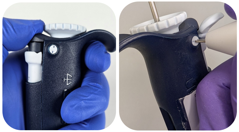
    The process of removing, replacing, and reinstalling the windows for ThermoFisher / Finnpipette pipettes requires great care, a high attention to detail, patience, and steady hands. Please dedicate a good work area with good lighting and space where small parts can be located should they pop/fly out during disassembly. Pipette damage and lost parts may occur if attention to detail is not maintained. Please proceed at your own risk.

    These instructions are intended for the following pipette models: Finnpipette I, II, Digital, Focus, Novus, F-Series

    Replacement Parts:

    1. Digital/Finnpipette II Windows: Volume Specific
    2. Focus Windows: Volume Specific
    3. Novus Window/Lens: Universal

    Recommend Supplies:

    1. Pair of gloves
    2. Bottle of 70% IPA
    3. Cotton Swabs
    4. Flat-head screwdriver
    5. Phillips-head screwdriver(Novus)

    Digital/Finnpipette II Window Replacement Steps:
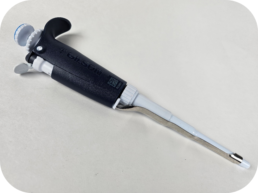
    Step 1:

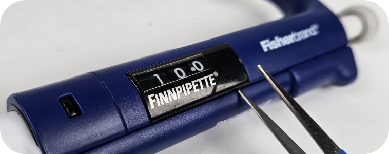
    Start with the pipette on a flat surface, with the window/counter facing up. Insert a flat-head screwdriver or shim at the bottom of the window, where the Finnpipette name is printed. Ensure that the screwdriver or shim is positioned at the bottom of the window. Apply upward pressure to disengage the two tabs on either side of the window.

    Finnpipette window
    Step 2:

    It is a good idea to clean any debris from the inside edge of the window before reinstalling or replacing it. Use a cotton swab soaked in 70% isopropyl alcohol to clean these internal areas.
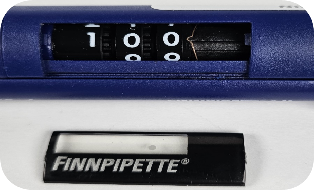
    Finnpipette window removal

    Step 3:

    To install the replacement window, line up the tab on the left side of the window with the side closest to the lower assembly. Once it is in place, push down on the window until the tab on the right side clicks into the other channel on the pipette body.
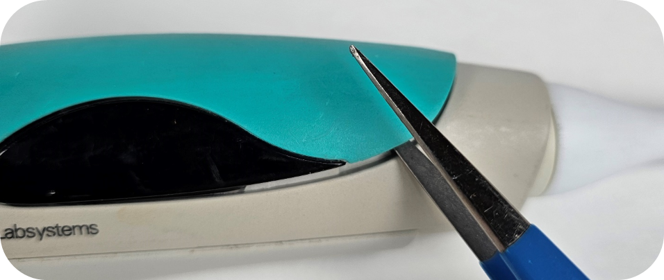
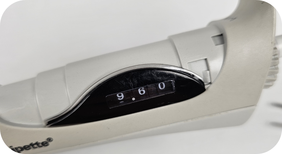
    Note: The window will not be flush with the pipette body when installed correctly (see picture below).

    Window not flush
    Focus Window Replacement Steps:
    Step 1:

    Using a flat-head screwdriver, pry up the soft grip cover on the finger hook side of the pipette. This grip is secured with a set of tabs on the top and bottom, along with a channel that holds the window/panel in place on both sides.

    Removing old window
    Step 2:

    Remove the old window and replace it with a new one. The window can be easily removed by inverting the pipette or lifting the window up.
    window removed
    Step 3:

    Aligning the window/panel with the soft grip handle can be tricky. The picture below shows the channel on the soft grip that interacts with the top clear edge of the window (see picture above).

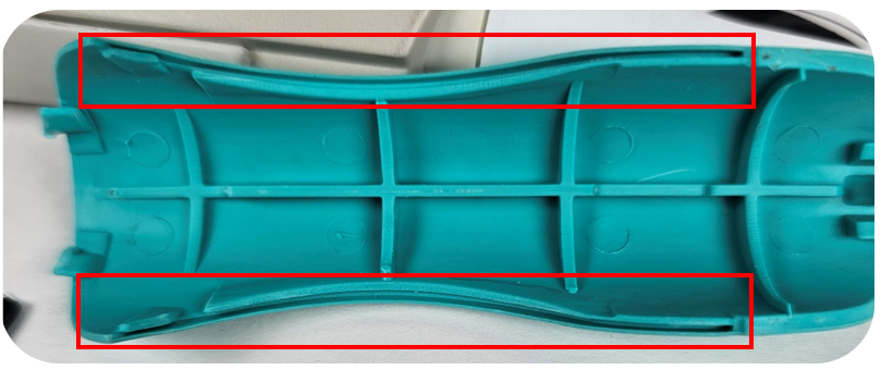
    Tabs and groves from soft grip
    Step 4:

    After installing the new window(s), you are ready to reassemble the pipette. Start near the finger hook by inserting the two tabs from the soft grip (shown in the picture above, far left) into their respective slots on the pipette body.

    tab slots

    Note: Picture below indicates where the tabs are located that interact with the two slots on the pipette body.

    inner tabs
    Step 5:

    It may take a few tries to align the windows with the channels outlined in Step 3. If you have trouble, you can use a flat-head screwdriver to make adjustments once the soft grip is flat.

    Note: The grip does not fit tightly against the pipette body. There may be some space or slightly flared corners on the soft grip after securing the window correctly.

    Novus Window Replacement Steps:

    Step 1:

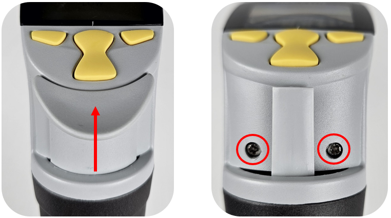
    Remove the ejector button by pulling up on the ejector. This will expose two phillips-head screws.

    Remove the ejector button
    Step 2:

    Remove both screws and set them aside.

    Step 3:

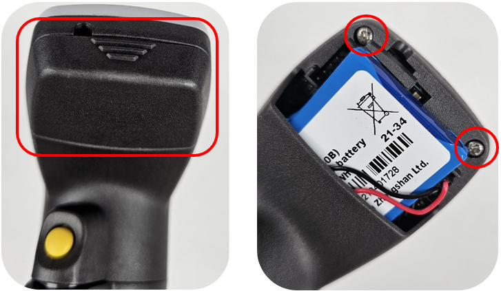
    Flip the pipette around and remove the battery door. Afterward, remove or disconnect the battery to prevent any potential damage while working on the unit. Additionally, remove the last two screws securing the frame in place.

    Remove battery cover
    Step 4:

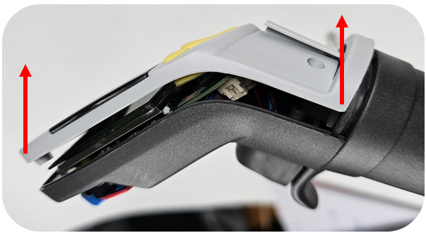
    Carefully lift the top edge away from the battery compartment. Once some space is created, use a flat-head screwdriver to pry the lower part away from the back of the pipette.

    remove Finnpipette window
    Step 5:

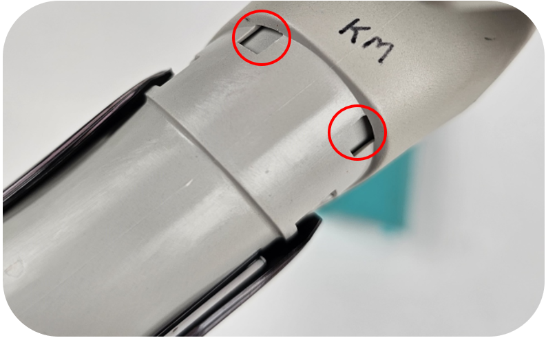
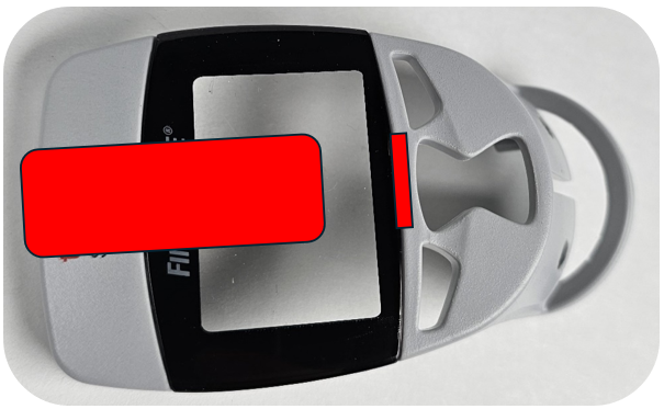
    After removing the light gray part/window from the pipette, hold the window with your left thumb over the red location marked in the picture below. With your right hand, gently bend the gray frame downward to create space at the bottom edge of the window.

    Note: The frame is fragile, so it is important to use your left hand to push up on the underside of the window to release the bottom tab (small rectangle outlined in the image below).

    thumb placement on Finnpipette window
    Step 6:

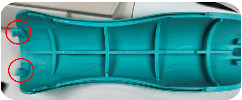
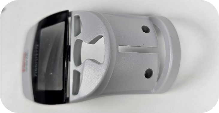
    Once the window is free at the bottom (see picture below), slide it away from the top edge. This step is important, as there is a thin plastic piece at the top of the frame that can easily break if you’re not careful.

    Finnpipette window
    Step 7:

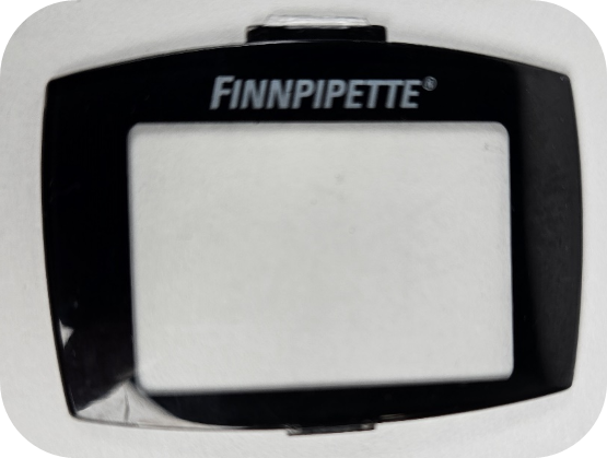
    Take the new window and insert the tab into the top of the frame. It’s important to gently bend the frame downward with your right hand to create space for the second tab. This is the same step we performed in Step 6. See the picture below that outlines the tabs on the top and bottom of the window.

    Finnpipette window
    Step 8:

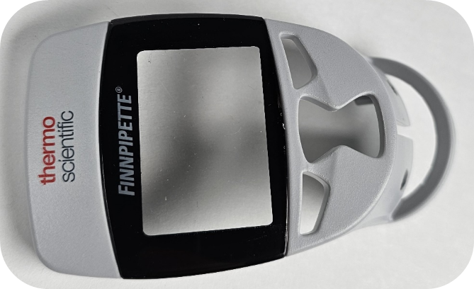
    Insert the silicone keypad into the frame. This is a good time to ensure there is no debris or fingerprints inside the window before reassembling the pipette. A cotton swab with some 70% isopropyl alcohol can be used to clean these internal surfaces.

    Note: Make sure the part is dry before reinstalling, as alcohol can damage electronic components.

    replaced Finnpipette window
    Step 9:

    Note the channel at the bottom of the frame. This lines up with a corresponding channel on the pipette. When reattaching the frame, it’s easier to slide the frame over the ejector.

    reattaching frame
    Step 10:

    Once the frame is partially in place, focus on aligning the two channels. The best approach is to angle the frame at a 30–45-degree angle and gently push the bottom of the frame into position.

    reassembling window
    Step 11:

    Press down on the frame to ensure it is fully seated, with no gap present between the frame (light gray) and the back clamshell (dark gray). Reinstall the long screws on either side of the ejector (refer to Step 1) and the short screws above the battery in the battery compartment (refer to Step 3).

    reassembled
    Step 12:

    Reattach the battery connector and battery door (refer to Step 3). Check to ensure the ejector and aspirate/dispense buttons are working properly.

    reattach battery cover

    Note: The F2, F3, and Fisherbrand Elite pipettes do not have a replacement window available. While it is possible to use a window from the same model, it is not advised, as the window has a very thin and fragile border edge that can easily be damaged during installation. If needed, you can use a flat-head screwdriver to pry out the window. If you attempt this, make sure the screwdriver is inserted far enough into the window to ensure it comes out as one piece. We have provided a picture below to demonstrate the correct position for the screwdriver/shim to limit damage to the window.

    removing window

    The following ThermoFisher Models have a machined/glued in window and can’t be replaced, see list below:

    1. Finnpipette Colour
    2. Finnpipette I
    3. Finnpipette F1 & F1 ClipTip
    Related Posts:

    Preventive Maintenance: Fisherbrand Elite Single Channel (2uL-1000uL)
    Finnpipette Novus Error Codes
    Finnpipette Digital (Model 4500) Single Channel: How to Service and Replace the Tip Ejector Assembly
    Finnpipette F1 and F2 Tip Ejector Mechanism Replacement

    Disclaimer: Any action you take using the information on this website is strictly at your own risk. The information herein does not constitute professional advice and is general in nature. We make no warranty that this information will meet your requirements, be safe, accurate, or error-free. Pipette Supplies, Inc. is not responsible for any errors or omissions, any results obtained from the use of this information, or any loss or damage arising out of the use of this information. This site is for educational purposes only.
    Fair Use: Copyright Disclaimer under section 107 of the Copyright Act of 1976, allows for “fair use” for purposes such as comments, criticism, teaching, scholarship, news reporting, and research.
    Fair use is permitted by copyright statute that might otherwise be infringing.

  • Eppendorf Xplorer Injection Molded Ring

    The Xplorer has a clear ring that is injection molded into the pipette to attach the upper and lower parts during manufacturing. Unfortunately, there is no way to replace the ring once it is broken. Users will need to replace the entire pipette.

    Disclaimer: Any action you take using the information on this website is strictly at your own risk. The information herein does not constitute professional advice and is general in nature. We make no warranty that this information will meet your requirements, be safe, accurate, or error-free. Pipette Supplies, Inc. is not responsible for any errors or omissions, any results obtained from the use of this information, or any loss or damage arising out of the use of this information. This site is for educational purposes only.
    Fair Use: Copyright Disclaimer under section 107 of the Copyright Act of 1976, allows for “fair use” for purposes such as comments, criticism, teaching, scholarship, news reporting, and research.
    Fair use is permitted by copyright statute that might otherwise be infringing.

  • VWR Ergonomic High-Performance Adjustment Knob Kit Repair

    The process of removing, replacing, and reinstalling the VWR Ergonomic High-Performance Adjustment Knob requires great care, a high attention to detail, patience, and steady hands. Please dedicate a good work area with good lighting and space where small parts can be located should they pop/fly out during disassembly. Pipette damage and lost parts may occur if attention to detail is not maintained. Please proceed at your own risk.

    Replacement Parts:

    LN SP29327 – Adjustment Knob Kit

    Recommended Supplies:
    1. Pair of gloves
    2. Bottle of 70% IPA
    3. Cotton Swabs
    4. Flat-head screwdriver
    Step 1:

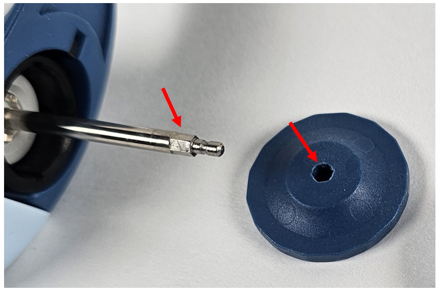
    Hold the VWR Ergonomic High-Performance pipette in one hand with the button facing towards you. With the other hand, pull the button away from the pipette body. Please note that the button has two parts. The blue lower has a hex hole that interacts with the operating rod and the top half snaps onto the top of the operating rod to secure both button parts in place.

    VWR Ergonomic High-Performance plunger button removal
    Step 2:

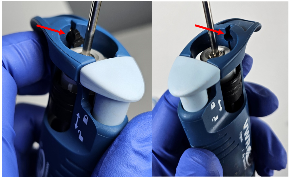
    Using a flat-head screwdriver, depress the tab of the bolt by pushing it towards the finger hook.

    tab removal

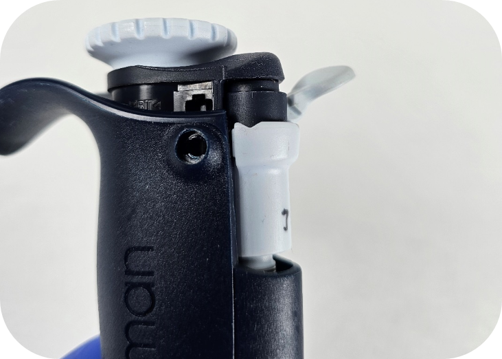
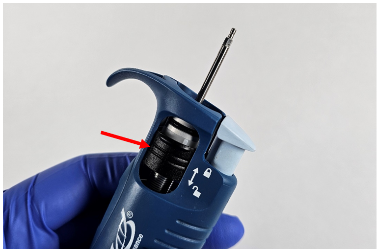
    While holding down the bolt (black tab retaining the knob), slide the knob (black cylinder) towards the top of the pipette.

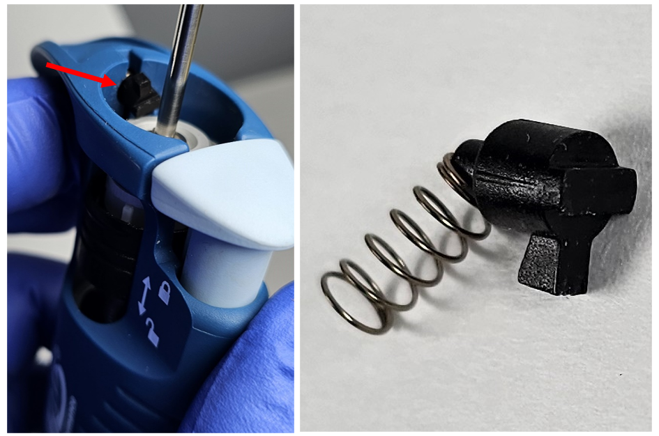
    Note: As you remove the knob from the pipette body, be careful not to lose the bolt and spring. The bolt and spring are under a decent amount of spring tension, and it is very easy to lose them.

    knob removal
    Step 3:

    Remove the bolt & spring from the keyed hole in the pipette body.

    removal of bolt and spring
    Step 4:

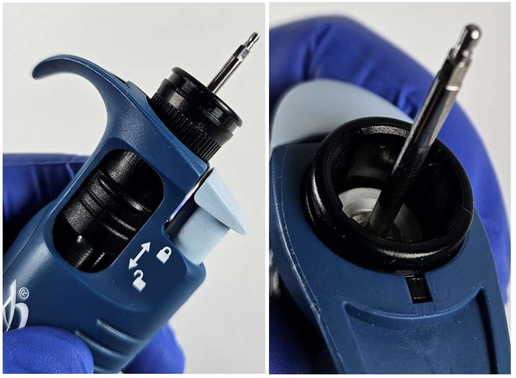
    Remove the locking ring by sliding it out the top of the pipette.

    VWR Ergonomic High-Performance locking ring

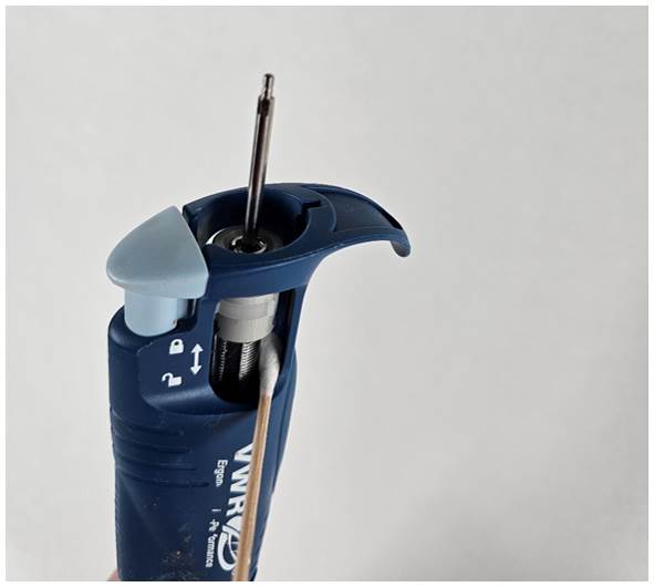
    Using a cotton swab (soaked in 70% isopropyl alcohol) to clean the surfaces in the pipette body that interacts with the adjustment knob assembly.

    cleaning
    Step 5:

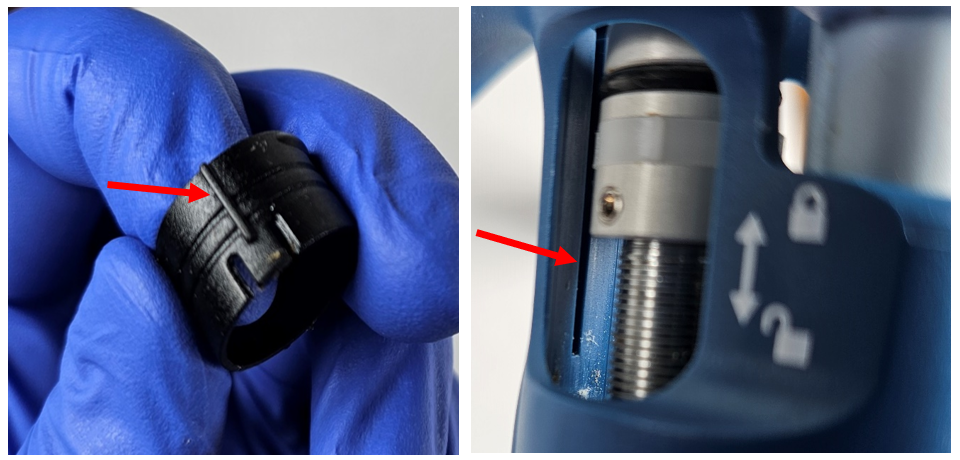
    Reinsert the locking ring. It is important to have it in the right orientation for a proper fit. The locking ring has a side with one fin on it. This side matches up with the channel on the counter side.

    Note: The tab on the locking ring faces down when it is inserted into the channel on the top of the pipette. The locking ring should fully seat in the pipette body.

    locking ring tab placement
    Step 6:

    Insert the spring and bolt into the designated hole in the body. Make sure to line up the bolt in the correct orientation (tab toward the top) to provide the clearance to seat the knob.

    seating the knob
    Step 7:

    Reinsert the knob (black cylinder), paying special attention to depressing the knob. After the knob is fully seated, the bolt will click into the channel on the top edge of the cylinder.

    VWR Ergonomic High-Performance knob insertion

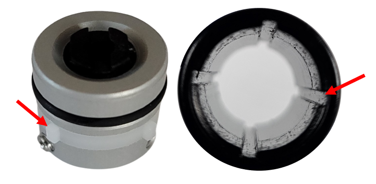
    Note: The knob is keyed to the calibration knob, line up the four fins with the channels in the knob. See the fins on the calibration knob and the channels in the knob (black cylinder) that interact with one another.

    calibration knob fins and channels
    Step 8:

    Fit the blue half of the button on the hex-shaped part of the operating rod.

    reassembling the plunger button

    Reattach the upper half of the button onto the end of the operating rod. You should feel a tactile click when the button is properly attached.

    VWR Ergonomic High-Performance plunger button fit

    Related Posts:
    Preventative Maintenance: VWR Ergonomic High-Performance (EHP) Single Channel Pipette
    How to Calibrate a VWR Ergonomic High Performance (EHP) Pipette
    Pipette Parts – Life Span, Life Cycle, and Performance
    Top 10 Crimes Committed Against Pipettes

    Disclaimer: Any action you take using the information on this website is strictly at your own risk. The information herein does not constitute professional advice and is general in nature. We make no warranty that this information will meet your requirements, be safe, accurate, or error-free. Pipette Supplies, Inc. is not responsible for any errors or omissions, any results obtained from the use of this information, or any loss or damage arising out of the use of this information. This site is for educational purposes only.
    Fair Use: Copyright Disclaimer under section 107 of the Copyright Act of 1976, allows for “fair use” for purposes such as comments, criticism, teaching, scholarship, news reporting, and research.
    Fair use is permitted by copyright statute that might otherwise be infringing.

  • Adjustment for Nichiryo Pipettes – Hex Key Tool

    These adjustment instructions cover the following Nichiryo models:

    • Nichiryo Oxford Benchmate I
    • Nichiryo Oxford Benchmate II
    • Nichiryo Nichipet
    • Nichiryo Nichipet EX
    • Nichiryo Nichipet EX II

    Notes:

    • Nominal Volume – The max volume a pipette can measure.
    • Before attempting calibration/adjustment, please make sure the sealing system(piston, tip holder and seal/o-ring) is functioning properly and is leak-free.

    Tool Needed:

    – Nichiryo/Oxford Hex Head Wrench Calibration Tool; Item#: NI 5G2-HEX

    Step #1:

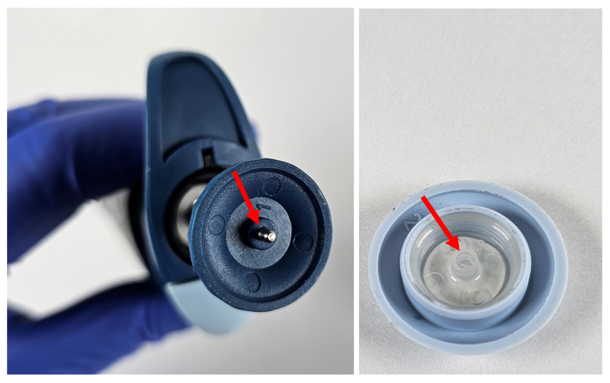
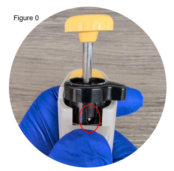
    Hold down the ejector button of the pipette and turn the locking lever/collar to expose the adjustment screw channel (figure #0).

    Step #2:

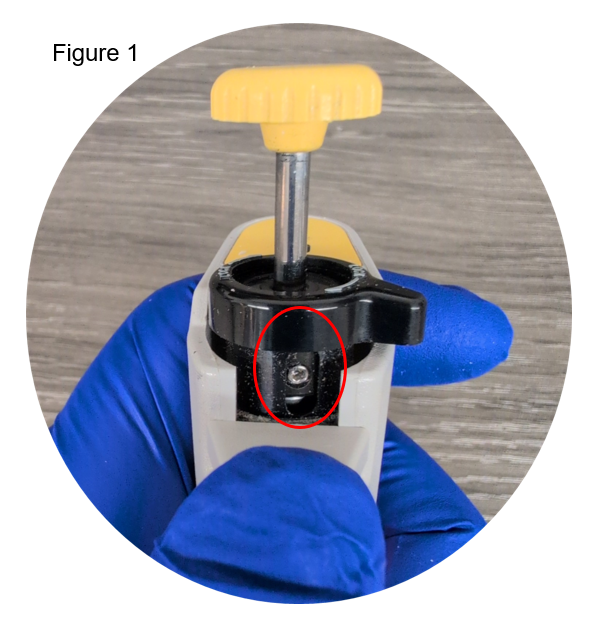
    Adjust the pipette to 75-80% of the nominal volume to get access to the set screws. See figure #1 below for the set screw location.

    Step #3:

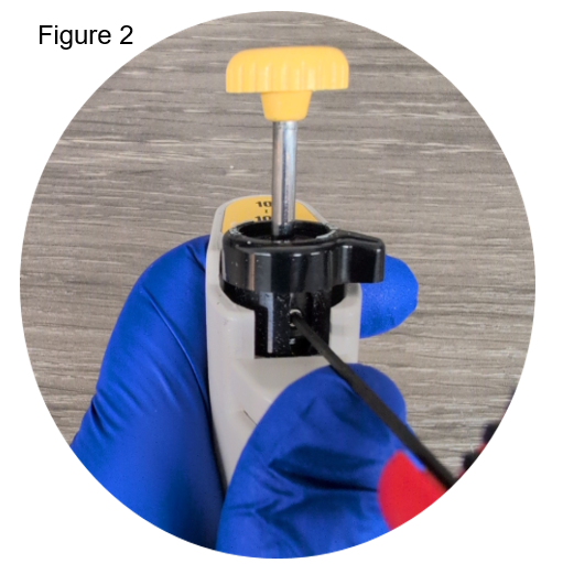
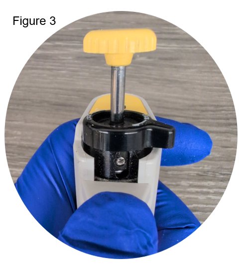
    Using the hex key, turn the first set screw counterclockwise one turn (see figure #2). Rotate the button a half turn(in either direction) to expose the second set screw on the opposite side of the adjustment screw (see figure #3).

    Step #4:

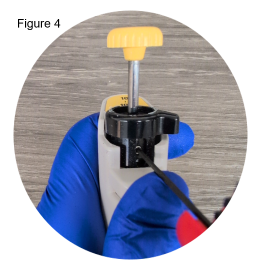
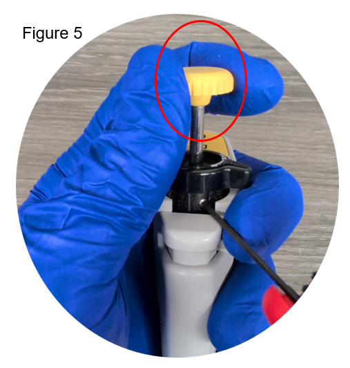
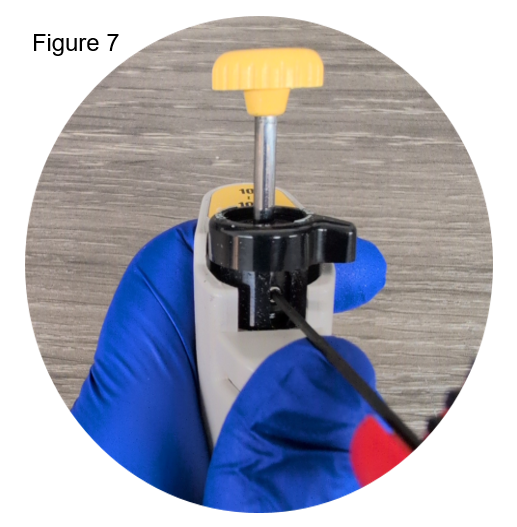
    Using the hex key, turn the second set screw counterclockwise one turn (see figure #4). With the hex key still in the second set screw, turn the button to adjust the volume (figure #5).

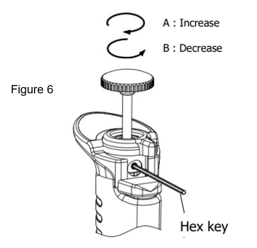
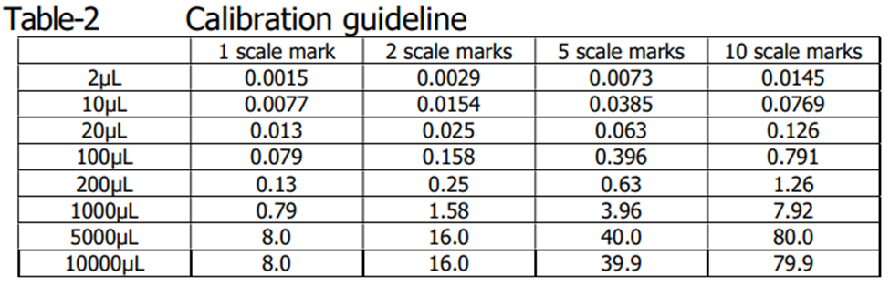
    To increase the volume, turn the button clockwise, and to degrease volume, turn the button counterclockwise (see figure #6). Note: Table-2 provides suggested adjustment values based on the nominal volume of a given pipette.

    The table below provides suggested adjustment values in microliters based on the nominal volume of the pipette. It is important to use a calibrated balance when adjusting and calibrating pipettes.

    Step #5:

    After adjusting the pipette, turn the hex key clockwise to tighten the set screw. It is important to only tighten one set screw at step #5, as it can take a few adjustments to get the desired value. Check the pipette at the 10% volume to ensure it is operating within specification and repeat steps 2-5 if additional adjustments are required.

    Step #6:

    After you have completed an adjustment, make sure both set screws are tight before returning the Nichiryo pipette to service (figure #7).

    Related Posts:

    Nichiryo Maintenance Videos
    Frequency of Pipette Preventative Maintenance and Calibration
    Pipette Parts – Life Span, Life Cycle, and Performance
    Do I need to verify the accuracy of all channels? (Multichannel Pipettes)

    Disclaimer: Any action you take using the information on this website is strictly at your own risk. The information herein does not constitute professional advice and is general in nature. We make no warranty that this information will meet your requirements, be safe, accurate, or error-free. Pipette Supplies, Inc. is not responsible for any errors or omissions, any results obtained from the use of this information, or any loss or damage arising out of the use of this information. This site is for educational purposes only.
    Fair Use: Copyright Disclaimer under section 107 of the Copyright Act of 1976, allows for “fair use” for purposes such as comments, criticism, teaching, scholarship, news reporting, and research.
    Fair use is permitted by copyright statute that might otherwise be infringing.

  • Preventive Maintenance: Fisherbrand Elite Single Channel (2uL-1000uL)

    The process of disassembly, removing, replacing, and reinstalling parts, as well as, performing preventive maintenance (PM) on the Fisherbrand Elite single channel pipette requires great care. A high attention to detail, patience, and steady hands are required. Please dedicate a good work area with good lighting and space where small parts can be located should they fly out during disassembly. Pipette damage and lost parts may occur if attention to detail is not maintained. Please proceed at your own risk.

    Recommended Tools:
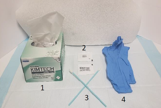
    1. Box of Kim Wipes
    2. Thermo Scientific Lubricant (Part#: TS 3300200)
    3. 2-3 Foam Swabs (applying new lubricant)
    4. Pair of latex gloves
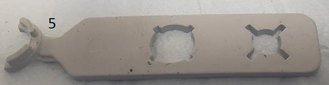
    5. PM/Calibration Tool (Part#: TS 1062800)
    6. Fisherbrand Elite Replacement Parts
    recommended tools
    PM/Calibration Tool (Part#: TS 1062800)
    Disassembly Process for PM and Part Replacement
    Step 1:

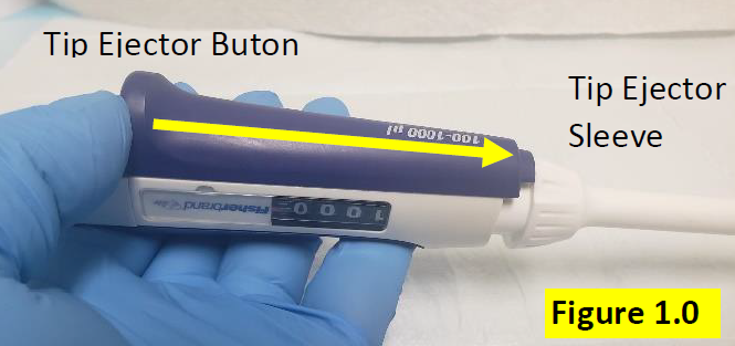
    Press and hold down the tip ejector button, in order to lower the white colored tip ejector sleeve. Figure 1.0.

    Remove Fisherbrand Elite tip ejector button
    Step 2:

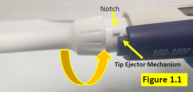
    Twist and turn the tip ejector sleeve to disengage it from the pipette body. Notice the square notch will become visible when properly disengaged from the pipette body, tip ejector mechanism. Figure 1.1.

    Notch on tip ejector
    Step 3:

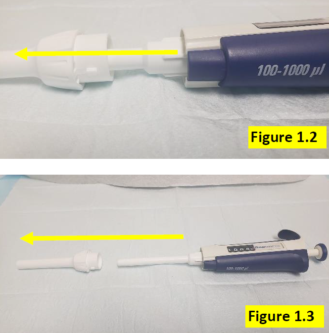
    Once tip ejector sleeve is disengaged, slide it down and off of the pipette shaft, as shown in Figure 1.2 and 1.3.

    Removing the ejector
    Step 4:

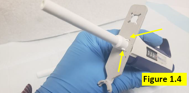
    With the tip ejector sleeve removed, insert the PM portion of the calibration tool over the shaft until it aligns with the slit marks on the upper portion of the shaft. Figure 1.4.

     Using the Fisherbrand Elite PM tool
    Step 5:

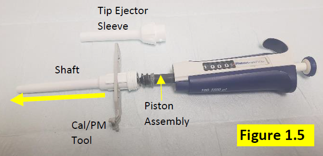
    Rotate the PM/Calibration tool counter clockwise to fully disengage the shaft from the pipette body. Figure 1.5.


    CAUTION: The contents inside of the shaft are under spring pressure. Use caution to avoid small parts and springs from popping out of the pipette/shaft, forcefully.

    Disassembled Fisherbrand Elite lower part
    Step 6:

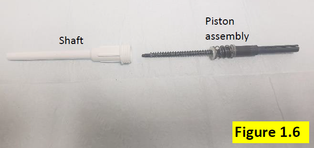
    With the shaft fully removed from the pipette body, gently slide out and remove the black colored internal piston assembly. Figure 1.6.


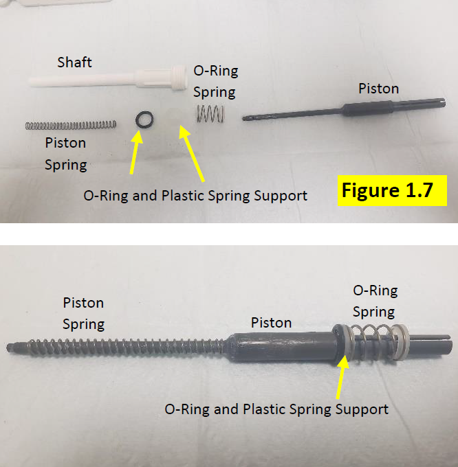
    When removing, ensure the following internal piston components are accounted for:

    • Large piston spring
    • Smaller o-ring spring
    • Plastic spring support
    • Piston o-ring
    Disassembled Fisherbrand Elite shaft
    Step 7:

    Remove all of the internal piston assembly components (Figure 1.7) for inspection, cleaning, and replacement as necessary. See Fisherbrand Elite Replacement Parts for these parts:

    • Large piston spring
    • Smaller o-ring spring
    • Plastic spring support
    • Piston o-ring
    • Lubricant
    • PM/Calibration tool
    Disassembled piston assembly
    Step 8:

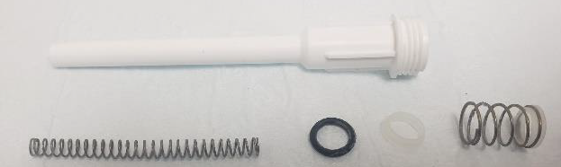
    Inspect, clean, and replace the parts as necessary. Fisherbrand Elite Replacement Parts

    Possibly parts for replacment
    Step 9:

    Clean and remove the old lubricant from the piston with a clean kim wipe. Repeat as necessary and dab the kim wipe with IPA if needed to remove lubricant.


    Step 10:

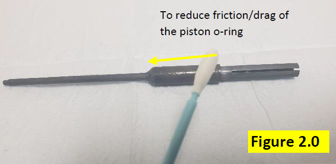
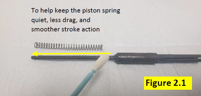
    Use a foam swab and apply a light but visible coating of lubricant onto the piston assembly. See figures 2.0 and 2.1 USE THE CORRECT LUBRICANT (Part#: TS 3300200).

    Adding lubricant to Fisherbrand Elite piston assembly
    lubricant application tips
    Reassembly Process After PM and Part(s) Replacement
    Step 11:

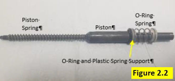
    Install inspected, cleaned, and/or new part(s) back onto the piston, as shown in Figure 2.2.

    Reassembled Fisherbrand Elite piston assembly
    Step 12:

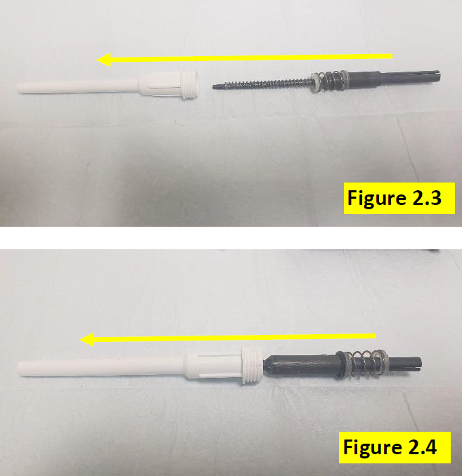
    Insert the piston assembly back into the shaft assembly. Figure 2.3 and 2.4.

    Reassembling the lower part
    Step 13:

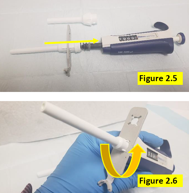
    With the piston assembly back inside the shaft, use the PM portion of the calibration tool to screw the shaft dully onto the pipette body. Figures 2.5 and 2.6. DO NOT OVER TIGHTEN.

    Reassembling the Fisherbrand Elite lower part
    Step 14:

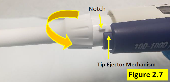
    Press the tip ejector button down and attach the tip ejector sleeve to the tip ejector mechanism. Rotate so the notch aligns and secures to the tip ejector mechanism. Figure 2.7.

    Aligning the notch
    Step 15:

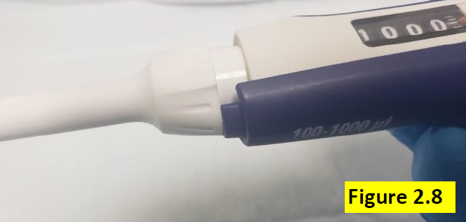
    Figure 2.8 shows notch has been rotated and now secured to the tip ejector mechanism.

    Secured Fisherbrand Elite tip ejector
    Step 16:

    Once pipette is fully assembled, allow the pipette to equilibrate for at least 60 minutes. After 60-minute equilibration period, verify the accuracy and precision on a 4-5 place gravimetric place balance.

    Related Posts:
    Finnpipette F1 and F2 Tip Ejector Sleeve Replacement
    Finnpipette Novus Error Codes
    Non-Linear Volume Readings – When Should A Calibration Adjustment Be Made?
    Top 10 Crimes Committed Against Pipettes

    Disclaimer: Any action you take using the information on this website is strictly at your own risk. The information herein does not constitute professional advice and is general in nature. We make no warranty that this information will meet your requirements, be safe, accurate, or error-free. Pipette Supplies, Inc. is not responsible for any errors or omissions, any results obtained from the use of this information, or any loss or damage arising out of the use of this information. This site is for educational purposes only.
    Fair Use: Copyright Disclaimer under section 107 of the Copyright Act of 1976, allows for “fair use” for purposes such as comments, criticism, teaching, scholarship, news reporting, and research.
    Fair use is permitted by copyright statute that might otherwise be infringing.

  • Preventive Maintenance: Rainin E4 XLS/XLS+ Single Channel – Piston Assembly

    The process of performing preventive maintenance (PM) on the E4 XLS/XLS+ requires great care, a high attention to detail, patience, and steady hands. Please dedicate a good work area with good lighting and space where small parts can be located should they fly out during disassembly. Pipette damage and lost parts may occur if attention to detail is not maintained. Please proceed at your own risk.

    Disclaimer: These instructions are only applicable for the Rainin E4 XLS if the pipette has been upgraded with the lip seal and black colored seal retainer. See this post for more information. The instructions are applicable for all E4 XLS+ pipettes.
    Recommended Supplies:
    1. Needle Nosed Pliers (to loosen piston assembly)
    2. Pipette Supplies 55g of Lip Seal Lubricant. Item# 2XLSGR55
    3. A box of kim wipes (to remove old lubricant from piston assembly)
    4. A bottle of 70% IPA (to clean piston assembly)
    5. Pair of laboratory gloves for PM process
    6. E4 XLS+ Single Channel Replacement Parts (as needed)
    Recommended supplies for E4 XLS preventative maintenance
    Step 1:

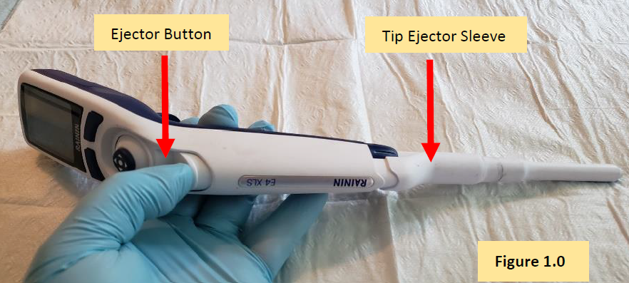
    Press and hold down the tip ejector button, as shown in Figure 1.0. This will cause the white colored E4 XLS tip ejector sleeve to be lowered for easier removal from the pipette body.

    Press E4 XLS ejector button
    Step 2:

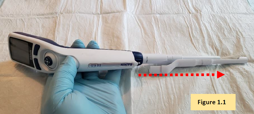
    Slide off and disengage the tip ejector sleeve from the pipette body. Figure 1.1.

    Remove E4 XLS tip ejector
    Step 3:

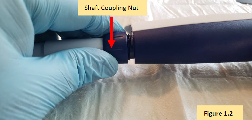
    Turn the shaft coupling nut clockwise to remove the shaft from the pipette body. Figure 1.2.


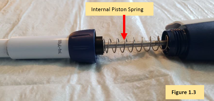
    CAUTION: When unscrewing the coupling nut, there is an internal piston spring that is under tension. Caution is needed to prevent small parts from popping out from inside of the shaft. It’s strongly recommended to unscrew the coupling nut over a table.

    Remove E4 XLS coupling nut

    COMMENT: With the shaft coupling nut disengaged from then pipette body, you will see the internal piston assembly, with spring. Figure 1.3.

    Internal piston spring
    Step 4:

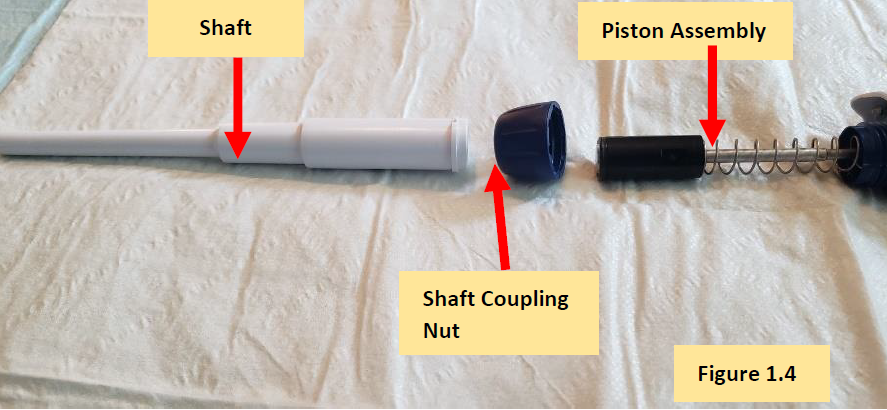
    Remove the shaft from the E4 XLS pipette body and fully expose the internal piston, spring, seal retainer, and lip seal. Figure 1.4.

    Disassembled E4 XLS lower part
    Step 5:

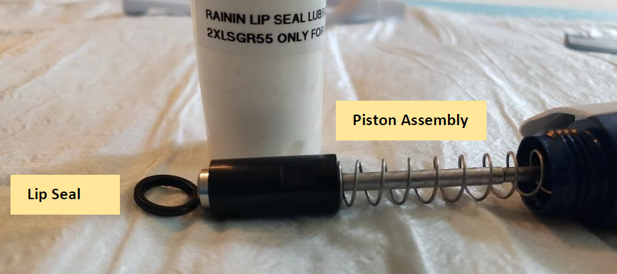
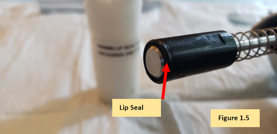
    Locate and remove the lip seal from the piston assembly. Figure 1.5.

    Lip Seal

    COMMENT: With the lip seal removed, now the focus shifts to servicing the piston assembly.

    E4 XLS piston assembly and lip seal

    COMMENT: Only, follow the next steps if the piston needs to be removed and/or replaced. If not, proceed to Step 7.


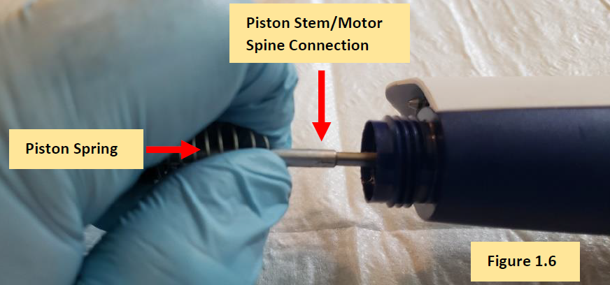
    Step 6:

    Collapse the piston spring with a gloved hand to expose the piston stem and motor spine connection. Figure 1.6.

    Piston stem/motor spine connection
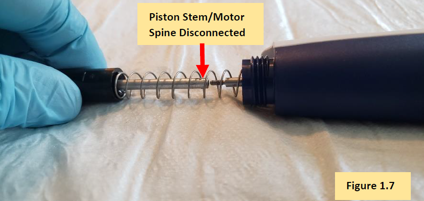
    Step 6.1:

    Unscrew the piston stem from the motor spine until it is fully detached. Figure 1.7.

    Disconnected E4 XLS piston stem/motor spine
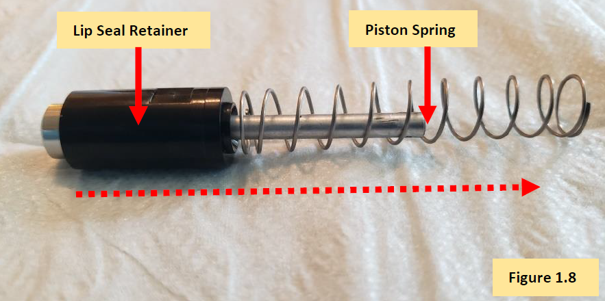
    Step 6.2:

    Slide and remove the piston spring from the piston spine, followed by removal of the black colored lip seal retainer. Figure 1.8.

    Remove piston spring from piston spine
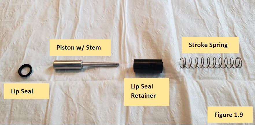
    Step 6.2 COMMENT:

    Figure 1.9 shows lip seal, piston, piston spring, and seal retainer removed from the motor spine.

    Disassembled E4 XLS piston assembly
    Step 6.3:

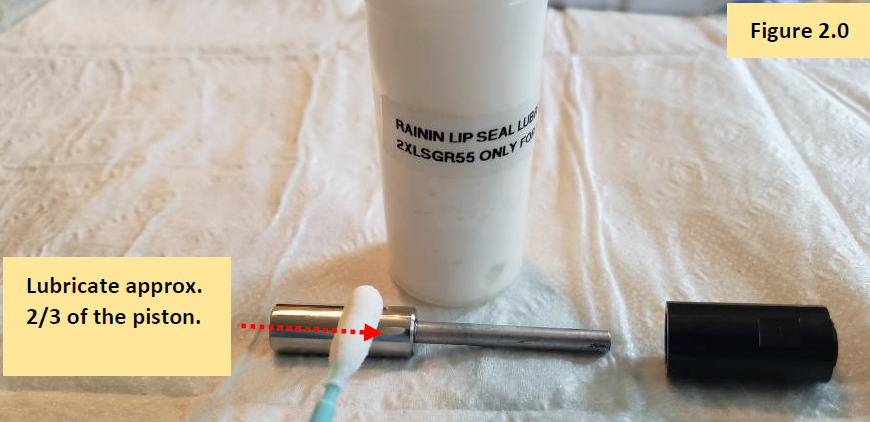
    Clean and remove the old lip seal lubricant with 70% IPA and Kim Wipes. Once the E4 XLS piston is cleaned, use a foam swab to apply a light, but visible, coat of lip seal lubricant
    (Item# 2XLSGR55) to the piston.

    NOTE: It’s not necessary to lubricate the entire piston. Lubricate approximately 2/3 of the piston. Figure 2.0.

    Grease on E4 XLS piston
    Step 7.0:

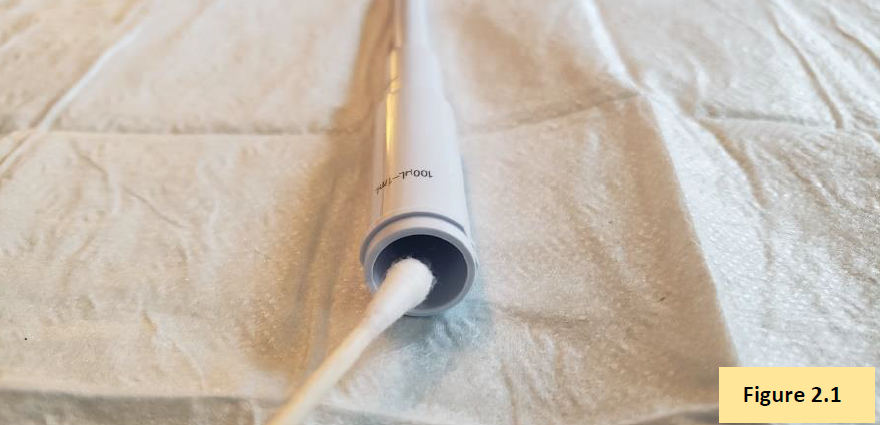
    With a foam swab, Q-Tip, and IPA, clean inside of the shaft to remove any chemical splash, lubricant, etc. If needed, replace shaft. Figure 2.1.

    (See E4 XLS+ Single Channel Replacement Parts)

    Lubricating inside of tip cone
    Step 7.1:

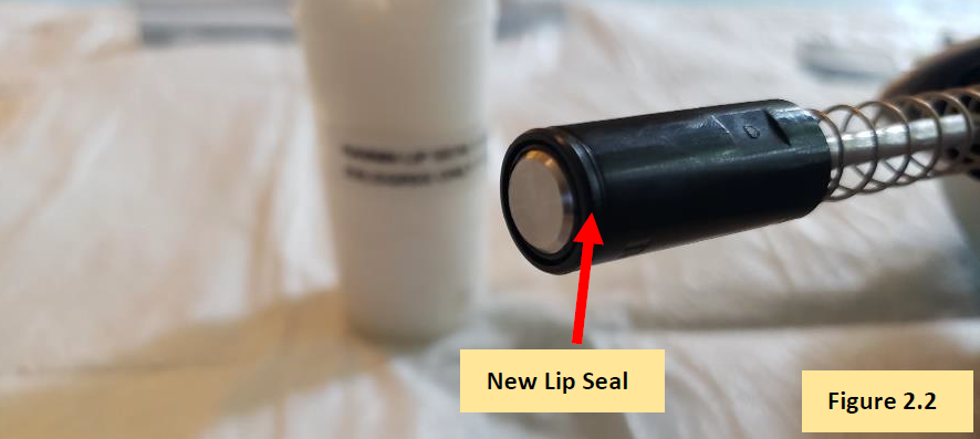
    Install a new lip seal onto the piston. Figure 2.2. (See E4 XLS+ Single Channel Replacement Parts)

    New E4 XLS lip seal replacement
    Step 7.2:

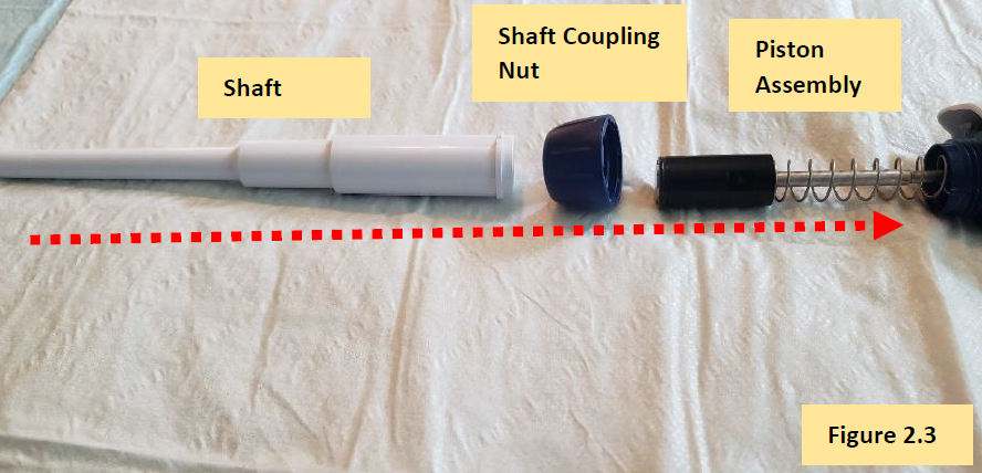
    Affix and reattach the shaft to the shaft coupling nut. Figure 2.3.

    reassembling the lower part
    Step 7.3:

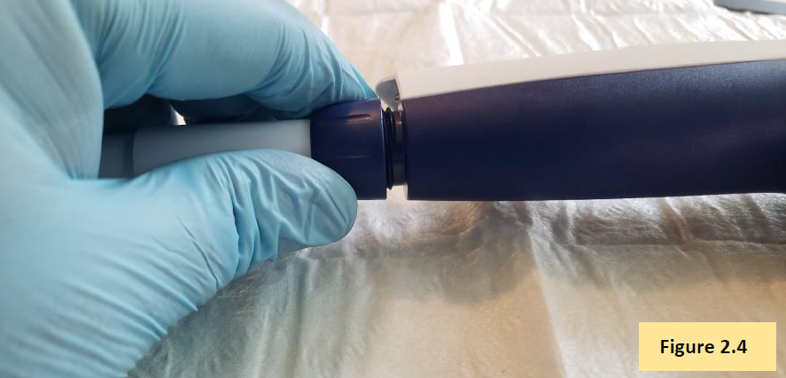
    Screw the shaft coupling nut and shaft back onto the pipette body. Figure 2.4.

    Attaching the E4 XLS coupling nut
    Step 7.4:

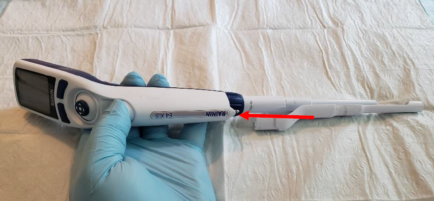
    Press and hold down the tip ejector button to extend the tip ejector rod from the bottom of the pipette. Affix the tip ejector sleeve to the exposed tip ejector rod. Affix a pipette tip to the pipette and aspirate/dispense Di water to check for leaks. If a leak is detected, recheck work. If no leaks are detected, allow pipette to equilibrate for 1 hour.

    Reattaching the tip ejector
    Step 7.5:

    After the 1-hour equilibration period has elapsed, check the E4 XLS pipette’s accuracy and precision performance on an analytical 4-5 place balance. Recheck work as needed.

    calibration with balance
    Related Posts:

    Seal/O-Ring Vs. Lip Seal for Pipet-Lite, Pipet-Lite XLS, and E4-XLS Models
    Rainin Pipette Legend
    Frequency of Pipette Preventative Maintenance and Calibration
    Top 10 Crimes Committed Against Pipettes

    Disclaimer: Any action you take using the information on this website is strictly at your own risk. The information herein does not constitute professional advice and is general in nature. We make no warranty that this information will meet your requirements, be safe, accurate, or error-free. Pipette Supplies, Inc. is not responsible for any errors or omissions, any results obtained from the use of this information, or any loss or damage arising out of the use of this information. This site is for educational purposes only.
    Fair Use: Copyright Disclaimer under section 107 of the Copyright Act of 1976, allows for “fair use” for purposes such as comments, criticism, teaching, scholarship, news reporting, and research.
    Fair use is permitted by copyright statute that might otherwise be infringing.

  • Preventative Maintenance: Transferpette S Single Channel (2uL-1000uL)

    The process of disassembly, removing, replacing, and reinstalling parts, as well as, performing preventive maintenance (PM) on the Brand Transferpette S single channel pipette require great care. A high attention to detail, patience, and steady hands are required. Please dedicate a good work area with good lighting and space where small parts can be located should they pop/fly out during disassembly. Pipette damage and lost parts may occur if attention to detail is not maintained. Please proceed at your own risk.

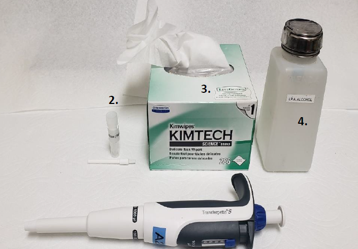
    Recommended Supplies
    1. Pair of gloves (not pictured)
    2. Transferpette S Silicone Oil item# BT 705502 (for use with up to 1000uL volume sizes)
    3. Box of Kim Wipes
    4. Bottle of IPA 70%
    5. Replacement parts

    NOTE: These instructions are for Transferpette S single channel pipettes that are between 2uL-1000uL volume sizes. It’s recommended that a 4-5 place analytical balance be used to check the accuracy and precision performance after PM and 1 hour equilibration period is completed.

    supplies needed for Transferpette S preventative maintenance
    Transferpette S Disassembly and Preventative Maintenance
    Step 1:

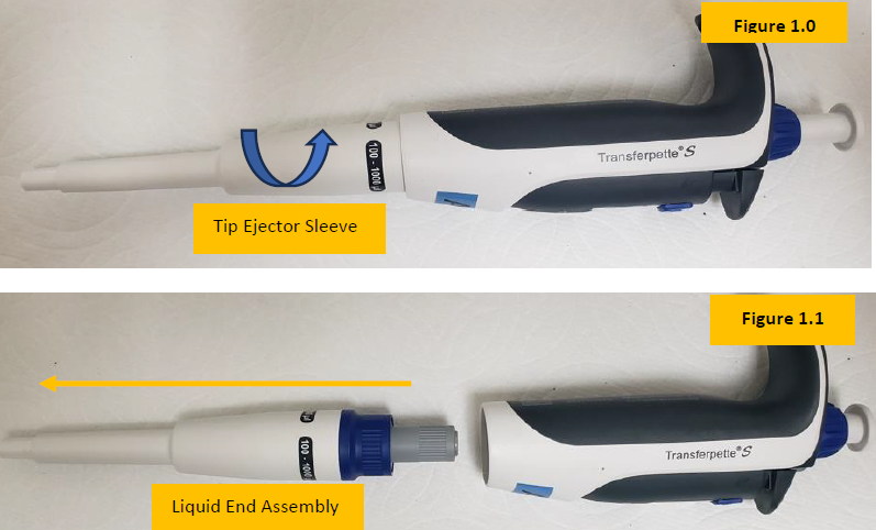
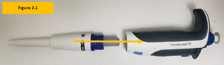
    Rotate and unscrew the Transferpette S tip ejector sleeve from the pipette body. See Figure 1.0

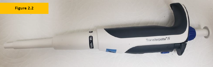
    Once fully unthreaded, the entire shaft assembly will detach from the pipette body, as shown in Figure 1.1.

    removing the lower part
    Step 2:

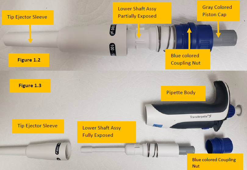
    Unscrew the blue colored coupling nut so that the tip ejector sleeve can be removed fully, thus exposing the lower shaft assembly. See Figure 1.2

    Observation: Figure 1.3 shows the lower shaft assembly fully visible and separated from the tip ejector sleeve.

    Disassembled Transferpette S with labels
    Step 3:

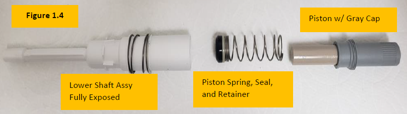
    Unscrew the gray colored piston cap to expose the internal piston, piston spring, seal and seal retainer. Remove fully from the Transferpette S lower shaft assembly. Figure 1.4

    Transferpette S lower part disassembled
    Step 4:

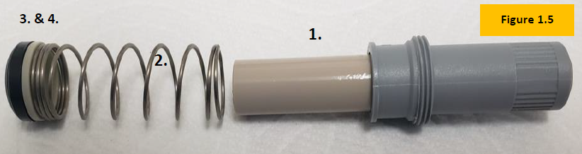
    Inspect the piston (1), piston spring (2), seal (3), and retainer (4). Figure 1.5. With a Kim wipe, clean and fully remove old lubricant from the piston, seal, and retainer.

    Piston Assembly
    Step 5:

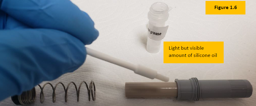
    Apply a light, but slightly visible amount of Transferpette S silicone oil onto the piston assembly. Figure 1.6

    Applying oil to the Transferpette S piston assembly
    Step 5A:

    Install a new seal assembly onto the retainer.

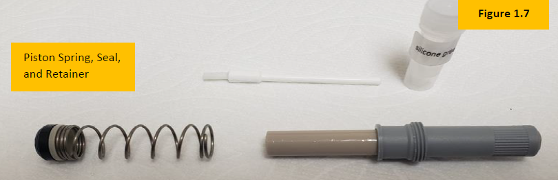
    Finished piston assembly
    Transferpette S Reassembly
    Step 6:

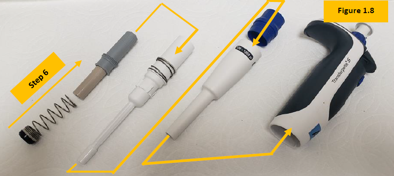
    Attach seal retainer to the piston spring. Slide the seal, retainer, and spring back onto the piston with gray cap. Figure 1.8


    Step 6A:

    Inspect and replace shaft, tip ejector sleeve, piston if needed.

    Reassembling the Transferpette S
    Step 7:

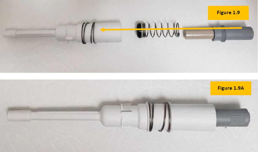
    Slide the piston assembly back inside of the lower shaft assembly. Turn and tighten the gray piston cap until the piston assembly is fully secured inside of the shaft. Figure 1.9 and 1.9A

    Reassembling the lower part
    Step 8:

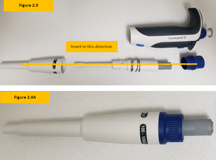
    Locate the blue colored coupling nut. Insert the lower shaft assembly into the tip ejector sleeve. Figure 2.0

    Rotate and turn blue colored coupling nut until the lower shaft is fully secured inside of the tip ejector sleeve. Figure 2.0A

    reassembling the lower part
    Step 9:

    Insert the liquid end assembly into the pipette body opening and rotate the tip ejector sleeve until it is tight with the body.

    Attaching Transferpette S lower part to handle
    Step 10:

    Once fully reassembled, allow the pipette to equilibrate for at least 60 minutes. After the equilibration period has passed verify accuracy and precision on a 4-5 place analytical balance.

    Reassembled Transferpette S
    Related Posts:

    Transferpette S Parts Decoded
    BrandTech Serial Number Format
    BrandTech Transferpette Multichannel Nose Cone Part Numbers

    Disclaimer: Any action you take using the information on this website is strictly at your own risk. The information herein does not constitute professional advice and is general in nature. We make no warranty that this information will meet your requirements, be safe, accurate, or error-free. Pipette Supplies, Inc. is not responsible for any errors or omissions, any results obtained from the use of this information, or any loss or damage arising out of the use of this information. This site is for educational purposes only.
    Fair Use: Copyright Disclaimer under section 107 of the Copyright Act of 1976, allows for “fair use” for purposes such as comments, criticism, teaching, scholarship, news reporting, and research.
    Fair use is permitted by copyright statute that might otherwise be infringing.