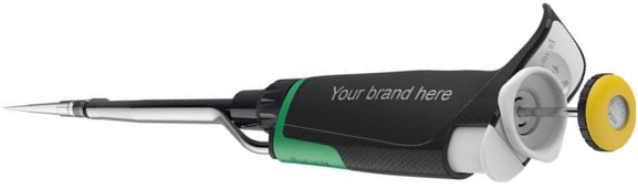
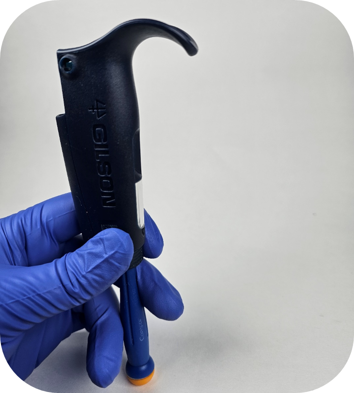
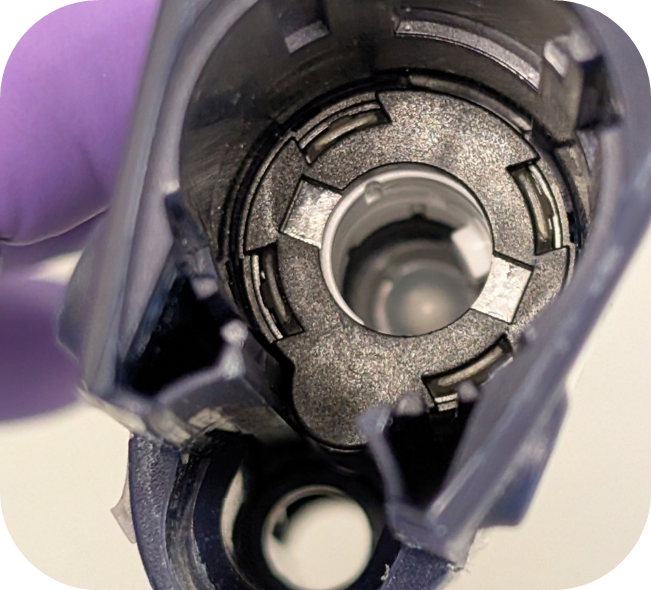
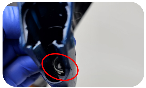
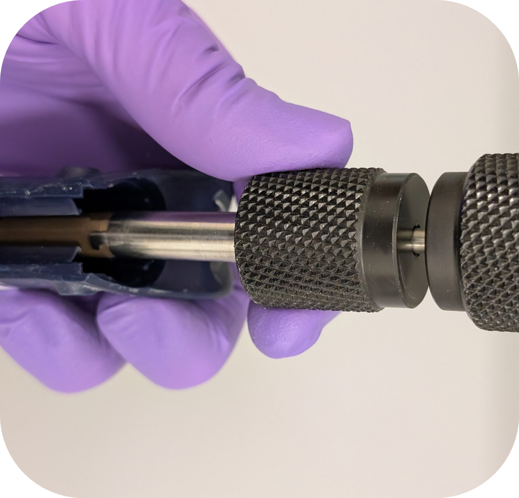
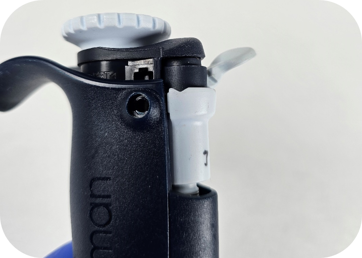
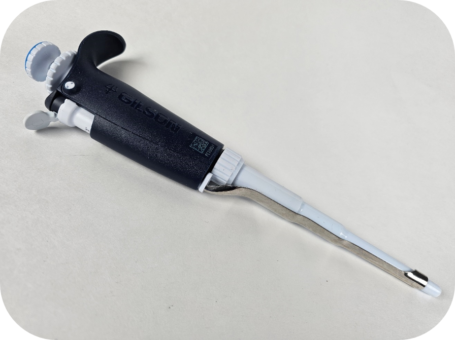
Gilson recently simplified their pipette model offerings to the Pipetman, Pipetman L, and Pipetman M.
The information below covers some additional changes in the lineup to assist with identification gaps missing from a previous post provided on identifying the Pipetman Classic product line.
See the previous post related to the first four iterations of the Gilson Classic lineup:
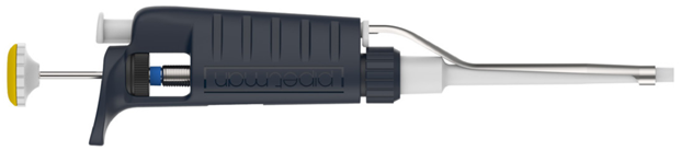
These two models are identical; the Pipetman G has simply been rebranded as the Pipetman. Gilson introduced the Pipetman in 2022, and its serial numbers start with T.
See the picture below for the Pipetman G & Pipetman:
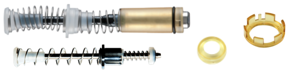
Seal Holder & Piston Assemblies:
Note: All sizes have a yellow seal holder with the exception of the 2µL (P2L).
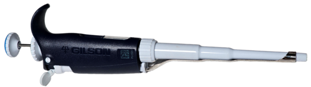
Pipetman L:
The presence of a finger hook and volume lock are the simplest indicators for identifying this model, as it was the first Gilson pipette to incorporate these features.
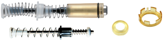
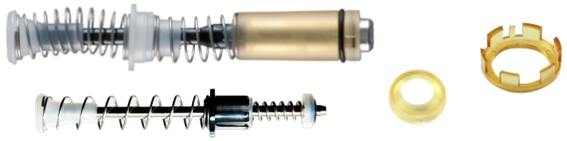
Seal Holder & Piston Assemblies:
Note: All sizes have a yellow seal holder with the exception of the 2µL (P2L).
My Pipetman:
This uncommon model offers extensive color customization. Although most parts from the Pipetman L are compatible, they may not match the existing color scheme.
Seal Holder & Piston Assemblies:
Note: All sizes have a yellow seal holder with the exception of the 2µL (P2L).
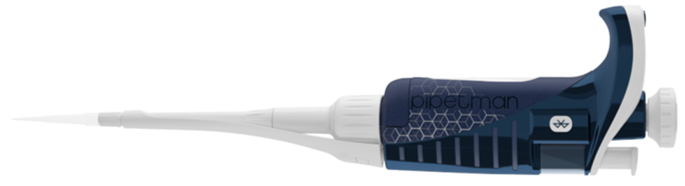
Pipetman M:
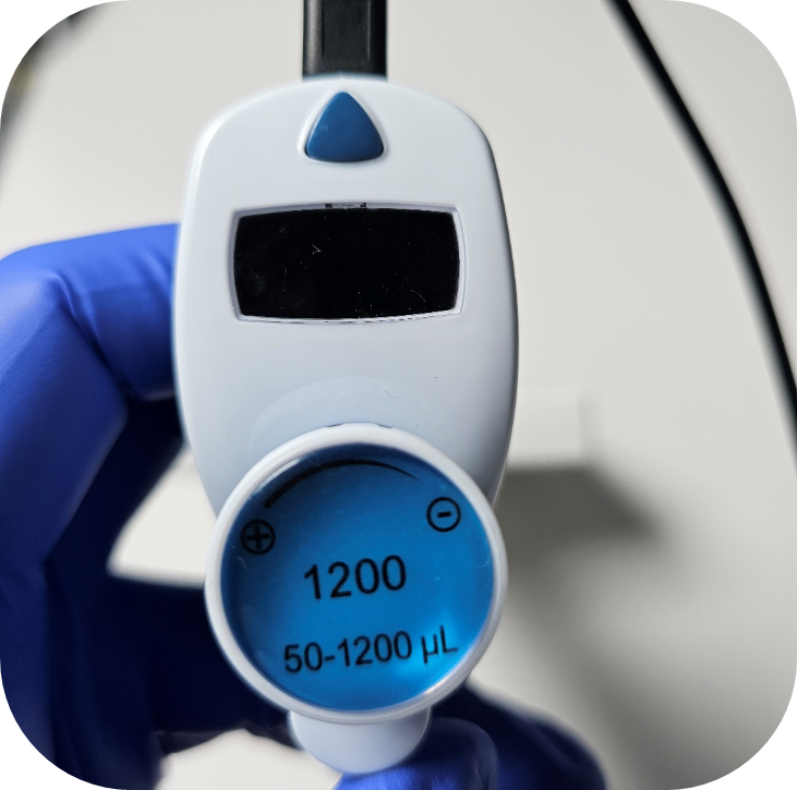
This is the sole electronic pipette in Gilson’s current product line. Two models are available: a standard version and a more recent, Bluetooth-enabled iteration. The connected model is designed for use with Gilson’s connected ecosystem (Trackman, PipettePilot, and Electronic Lab Notebook) and is identifiable by a Bluetooth symbol located on the side of the pipette body.
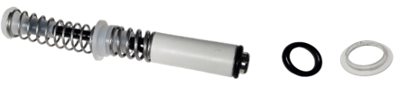
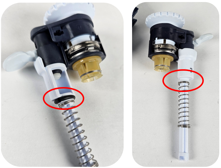
The last Classic model that was produced (started in June 2019, Serial #:QG-#####) utilized the Pipetman Neo parts. This included the piston assembly, updated button, and clip style tip ejector.
Neo piston assembly, seal, and o-ring.
Button & clip style tip ejector:
Disclaimer: Any action you take using the information on this website is strictly at your own risk. The information herein does not constitute professional advice and is general in nature. We make no warranty that this information will meet your requirements, be safe, accurate, or error-free. Pipette Supplies, Inc. is not responsible for any errors or omissions, any results obtained from the use of this information, or any loss or damage arising out of the use of this information. This site is for educational purposes only. Fair Use: Copyright Disclaimer under section 107 of the Copyright Act of 1976, allows for “fair use” for purposes such as comments, criticism, teaching, scholarship, news reporting, and research. Fair use is permitted by copyright statute that might otherwise be infringing.
The process of performing preventative maintenance for the Gilson Pipetman (formerly Pipetman G) and Pipetman L requires great care, a high attention to detail, patience, and steady hands. Please dedicate a good work area with good lighting and space where small parts can be located should they pop out during disassembly. Pipette damage and lost parts may occur if attention to detail is not maintained. Please proceed at your own risk.
The 2µL, 5mL, and 10mL models use the same seal and o-ring as the Pipetman Classic and Neo. Additionally, the Pipetman single channel has now replaced the Pipetman G. The new model uses the same parts as the Pipetman G.
Recommend Supplies:
Gloves
Cotton Swabs
Lint Free Wipe
Isopropanol (rubbing alcohol)
Step 1:
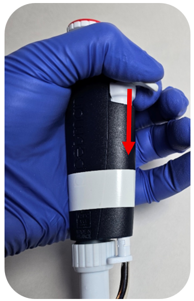
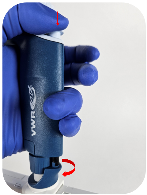
Press down the ejector button to expose the ejector clip.
Step 2:
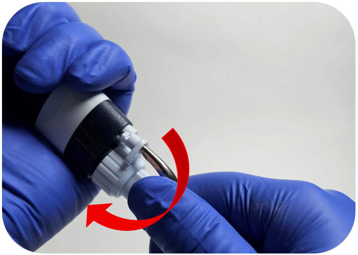
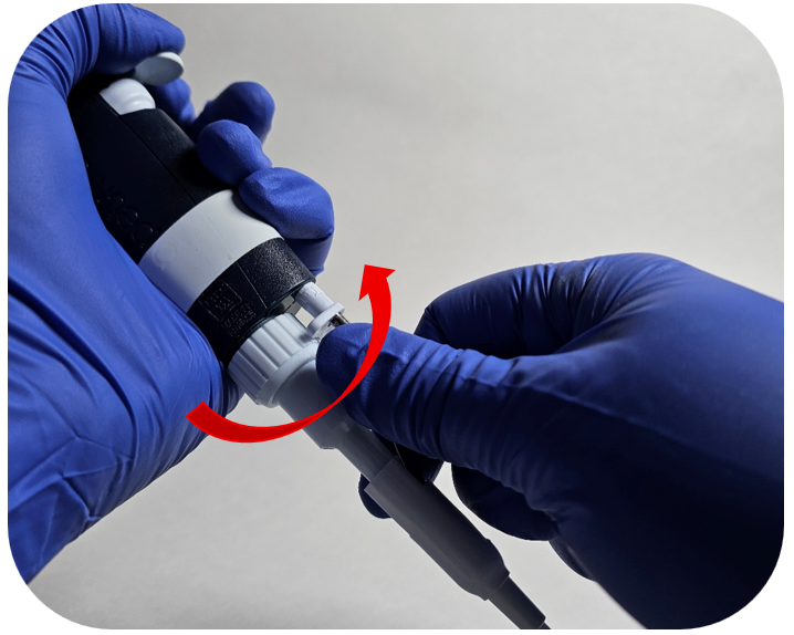
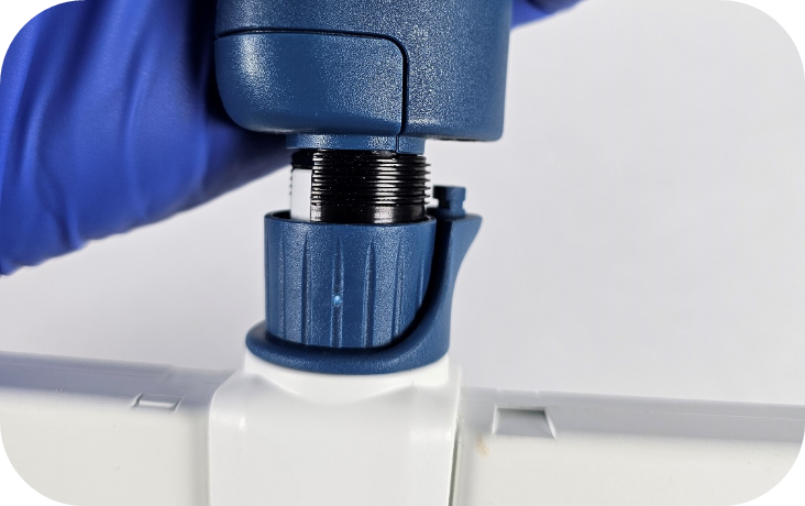
While holding the ejector button down, turn the tip ejector counterclockwise to unclip it.
Step 3:
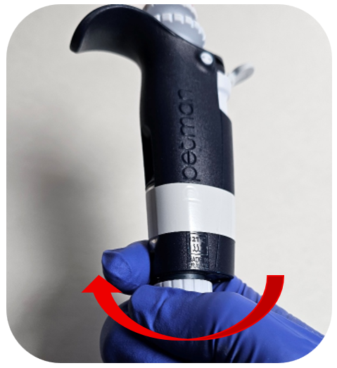
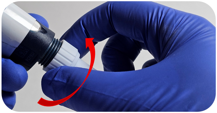
Turn the connecting nut counterclockwise to remove it from the pipette body.
Step 4:
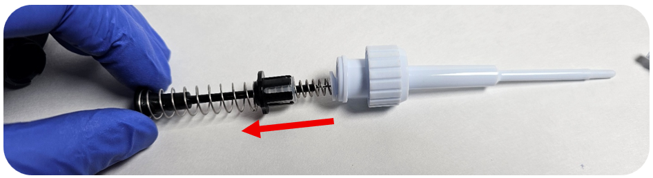
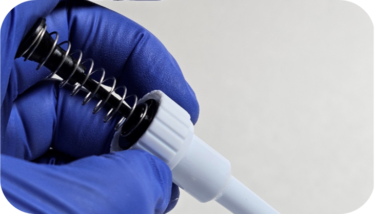
Remove the piston assembly from the tip holder.
Step 5:
Inspect the tip holder for any debris or seals/o-rings.
Step 6:
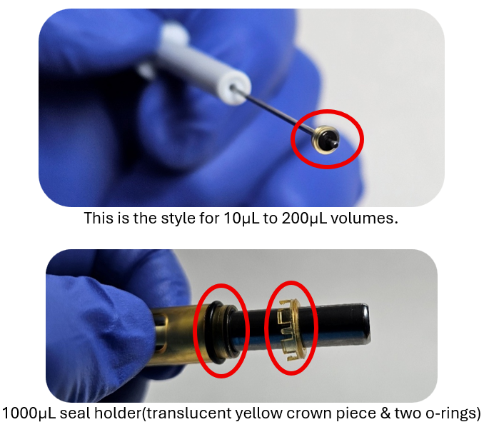
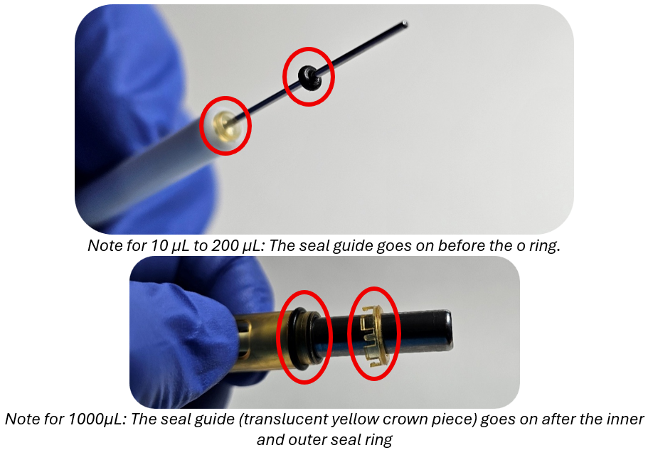
For 10µL to 1000µL models: Remove the seal guide and o-ring (or the inner and outer o-rings on the 1000 µL model) from the piston.
For 2µL, 5mL, and 10mL models: Remove the seal and o-ring from the piston.
Step 7:
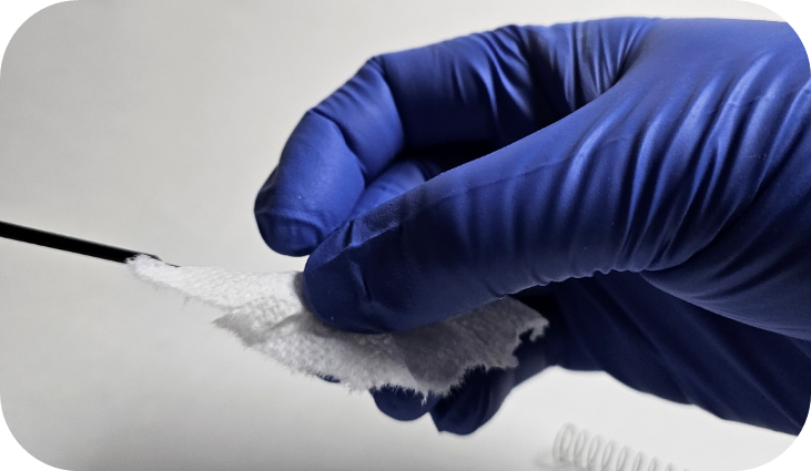
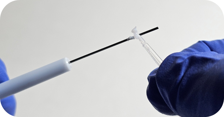
Clean the piston assembly using a lint free wipe moistened with isopropanol. Allow it to dry, then apply Gilson Pipetman G/L Grease.
Step 8:
For 10µL to 1000µL models: Install the seal guide and new o-ring (or inner and outer o-rings on the 1000µL model) onto the piston.
For 2µL, 5mL, and 10mL models: Install the new seal and o-ring onto the piston.
Step 9:
Reinsert the piston assembly into the tip holder and push it upward toward the pipette body.
For 5mL and 10mL models: Thread the tip cone onto the piston assembly.
Step 10:
Turn the connecting nut clockwise to secure it to the pipette body.
Note: For 5mL and 10mL models, the piston assembly will thread directly into the pipette body.
Step 11:
While holding the ejector button down, turn the tip ejector clockwise to clip it into the ejector assembly.
Disclaimer: Any action you take using the information on this website is strictly at your own risk. The information herein does not constitute professional advice and is general in nature. We make no warranty that this information will meet your requirements, be safe, accurate, or error-free. Pipette Supplies, Inc. is not responsible for any errors or omissions, any results obtained from the use of this information, or any loss or damage arising out of the use of this information. This site is for educational purposes only. Fair Use: Copyright Disclaimer under section 107 of the Copyright Act of 1976, allows for “fair use” for purposes such as comments, criticism, teaching, scholarship, news reporting, and research. Fair use is permitted by copyright statute that might otherwise be infringing.
The process of removing, replacing, and reinstalling the lower assembly on the Gilson Pipetman Neo, G, & L multichannel pipettes requires great care, a high attention to detail, patience, and steady hands. Please dedicate a good work area with good lighting and space where small parts can be located should they pop out during disassembly. Pipette damage and lost parts may occur if attention to detail is not maintained. Please proceed at your own risk.
Note: A new version of the tip holder featuring V-rings is available. Please verify whether the Pipetman Multichannel pipette in question is equipped with this updated tip holder.
Recommend Supplies:
Gloves
Flat-head screwdriver
Phillip-head screwdriver
Preliminary Note(s): The instructions cover the 10uL, 20uL, 200uL & 300uL multichannel pipettes.
Step 1:
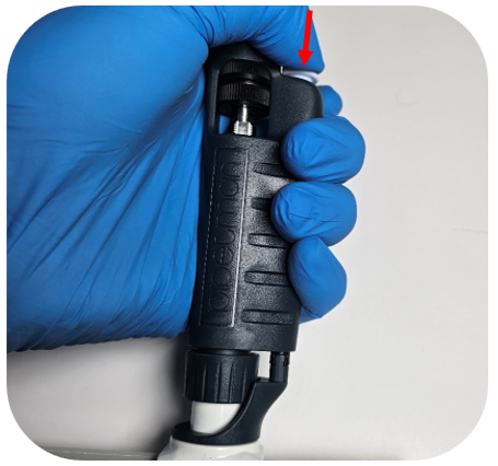
Press down the ejector button to expose the ejector clip.
Step 2:
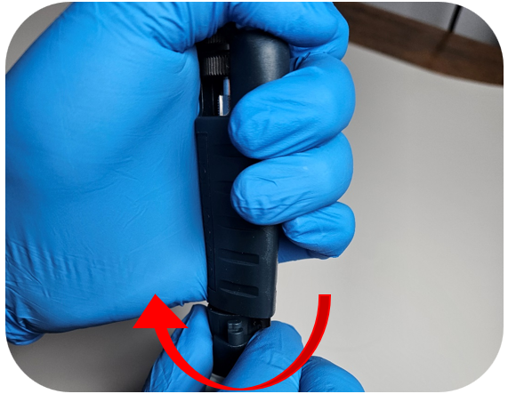
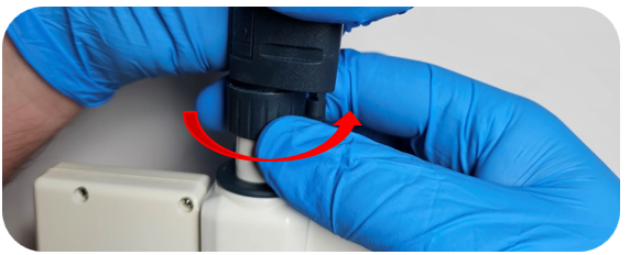
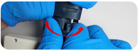
While holding the ejector button down, turn the ejector interface counterclockwise to unclip it.
Step 3:
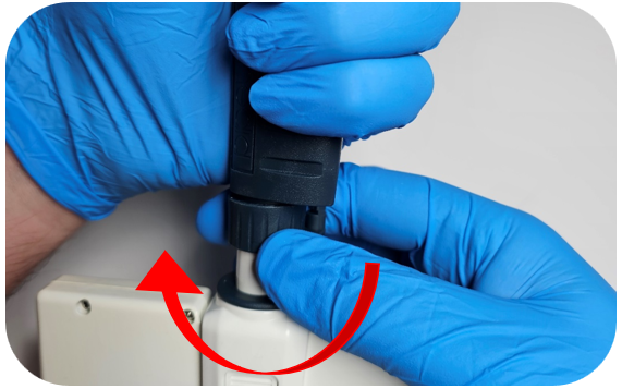
Turn the connecting nut counterclockwise to remove it from the pipette body.
Step 4:
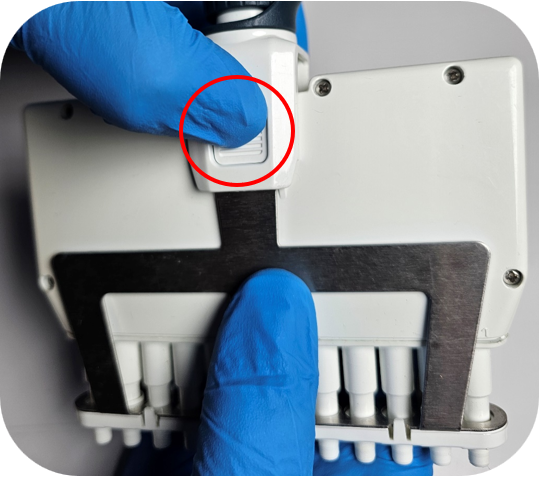
Remove the tip ejector by pressing the clip located on either side of the ejector interface.
Step 5:
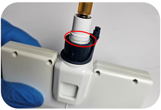
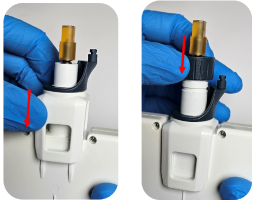
Ensure the connecting nut and ejector interface are in the down position. When both are down, the clear retaining clip should be visible.
Step 6:
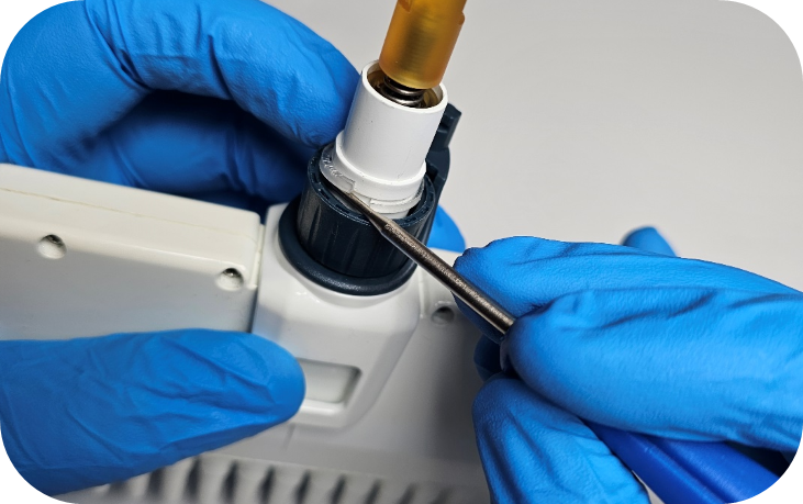
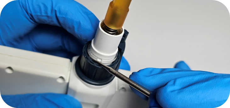
Using a small flat-head screwdriver, locate the open end of the clear retaining clip. Gently apply upward pressure on the underside of the clip to remove it.
Step 7:
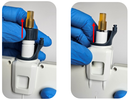
Once the clip is removed, detach the connecting nut and ejector interface from the lower assembly.
Step 8:
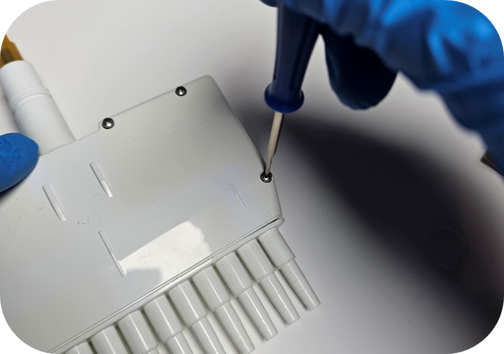
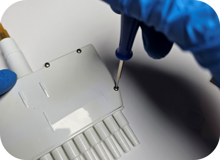
Remove all screws from the housing using a Phillips-head screwdriver.
Step 9:
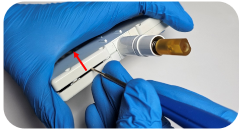
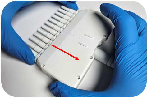
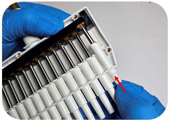
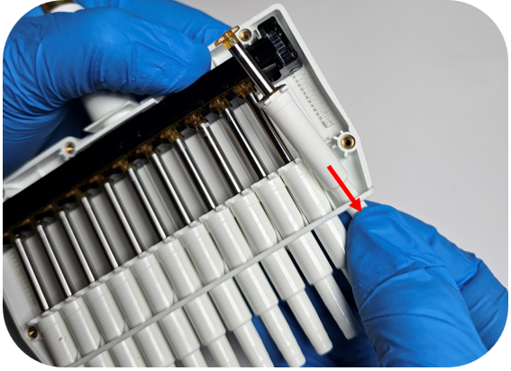
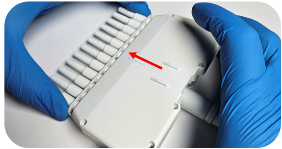
With the screws removed, carefully pry up the top section of the housing.
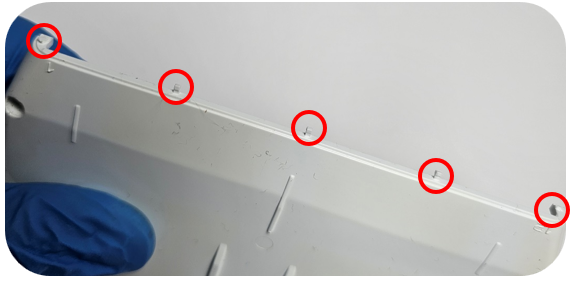
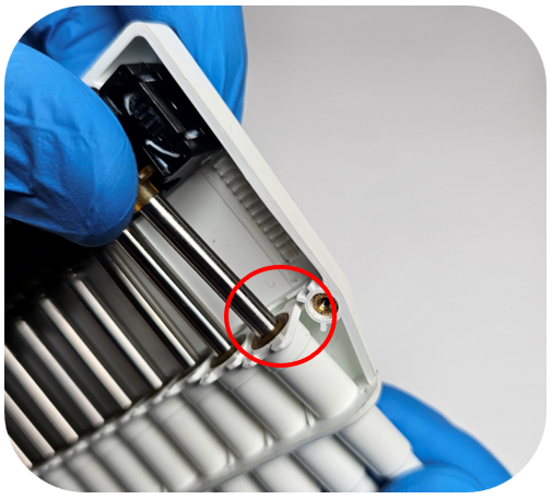
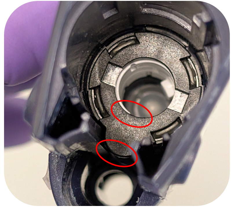
Note: Do not pry on the bottom end of the housing—plastic alignment tabs are located there and can be damaged. See the image below for the circled pin locations.
Step 10:
Lift up the top edge of the housing and pull it away from the bottom part of the housing to avoid damaging the plastic pins.
Step 11:
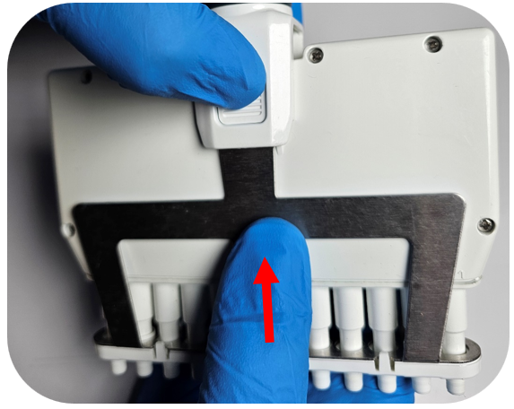
With the open side of the housing facing upward, press down on the tip holder to unseat the piston from the operating system.
Then push up on the tip holder to remove the piston assembly from the housing.
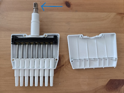
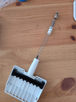
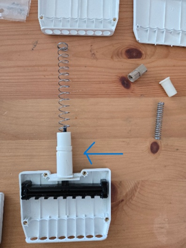
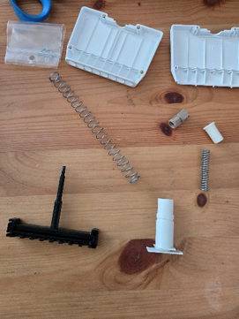
To Replace the Operating System / Manifold: In order to replace the housing you will need to remove the plunger, which can be done by unscrewing the top brown piece. Please USE CAUTION, there are two heavily wound springs being held in place by the screws and they will fly out if you are not keeping tension on the brown piece while unscrewing. Once the brown piece is unscrewed, remove the 2 springs from the top and the black plunger from the bottom. This white piece will also need to be removed from the old housing and clipped into the new housing. Place the black plunger into the housing and put both springs through the top and push down to screw the brown piece back in. Again, USE CAUTION because these springs will pop out if you’re not holding everything down with tension.
Step 12:
To reinstall the piston, insert the tip holder into the corresponding hole in the housing. While holding the tip holder, adjust the piston so it fits into the empty slot in the operating system.
Step 13:
Hold the top of the piston lightly in the operating system and align the tip holder tabs with the front and back housing channels. Apply gentle downward pressure on the tip holder to ensure it is fully seated.
Step 14:
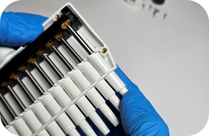
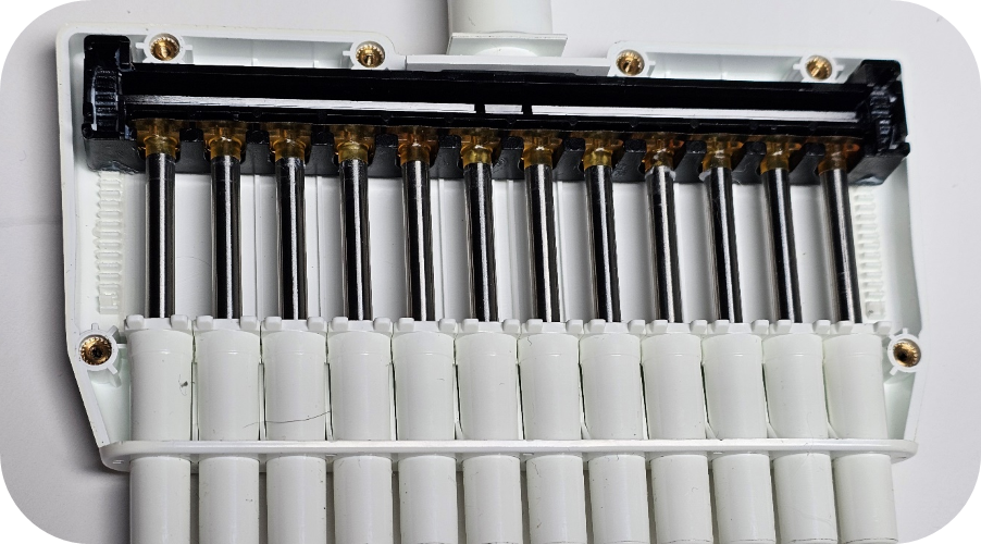
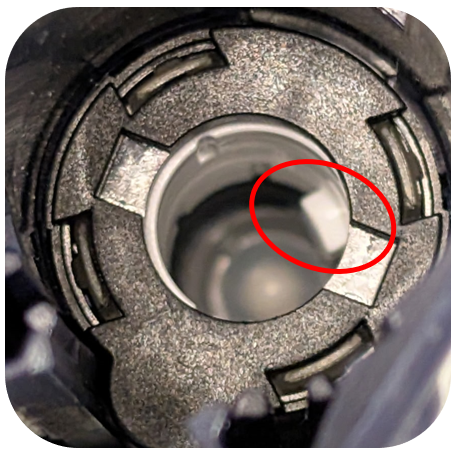
Before replacing the housing cover, confirm that the tops of the pistons are properly aligned (as shown below).
Step 15:
Insert the pins on the housing cover into the corresponding holes on the back half of the housing.
Step 16:
Press down on the top cover of the housing to ensure it is securely seated, then reinstall all screws using a Phillips-head screwdriver.
Step 17:
Attach the ejector interface to the top of the housing, followed by the connecting nut. Ensure all components remain in the down position.
Step 18:
Carefully press the clear retaining ring into place on the housing. You should feel a tactile “click” indicating it is fully locked.
Note: To confirm proper installation, pull gently on the connecting nut and ejector interface. If they cannot be removed, the retaining ring is correctly seated.
Step 19:
Reattach the connecting nut to the pipette body by turning the connecting nut clockwise.
Step 20:
Press down the tip ejector button and reclip the ejector interface by rotating the ejector interface towards the clip inside the pipette body.
Step 21:
Reinstall the tip ejector into the ejector interface, ensuring the ejector clips align with the grooves for a secure fit.
Disclaimer: Any action you take using the information on this website is strictly at your own risk. The information herein does not constitute professional advice and is general in nature. We make no warranty that this information will meet your requirements, be safe, accurate, or error-free. Pipette Supplies, Inc. is not responsible for any errors or omissions, any results obtained from the use of this information, or any loss or damage arising out of the use of this information. This site is for educational purposes only. Fair Use: Copyright Disclaimer under section 107 of the Copyright Act of 1976, allows for “fair use” for purposes such as comments, criticism, teaching, scholarship, news reporting, and research. Fair use is permitted by copyright statute that might otherwise be infringing.
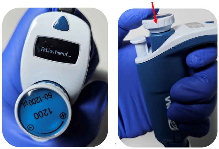
Note: You do not need any special tools to complete the adjustment for the Gilson Pipetman M.
Recommend Supplies:
Balance
Pipette Tips
Step 1:
Make sure the pipette has enough battery life before proceeding to the next step.
Step 2:
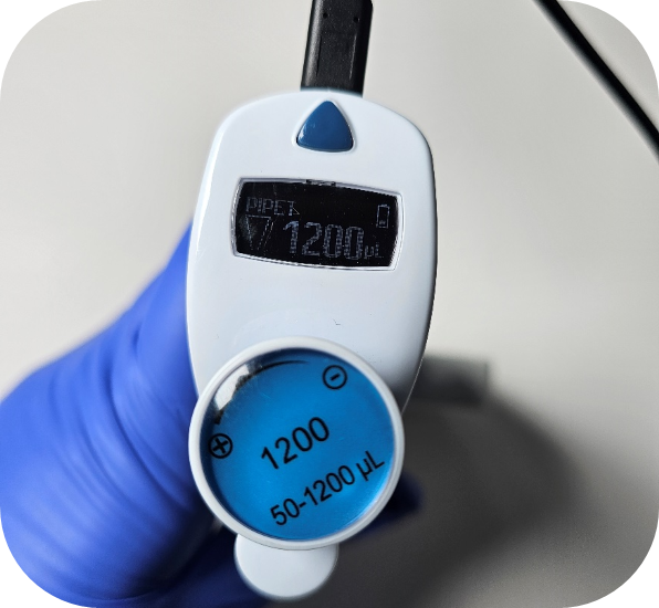
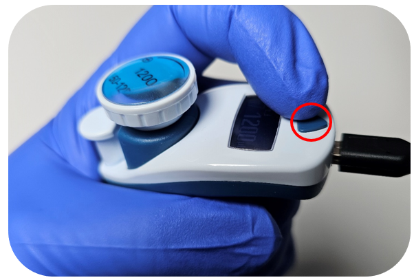
Start by turning on the pipette by pressing down on the dispense button.
Step 3:
Prior to adjusting the pipette, collect 2-3 data points at each test volume (low, middle, and high) on the balance. The data will be used in Step 7.
Step 4:
After the data points have been collected, click on the blue triangle button.
Step 5:
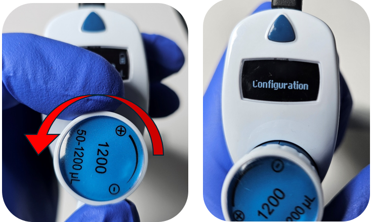
Turn the adjustment wheel counter-clockwise to “Configuration” and press down on the dispense button.
Step 6:
Turn the adjustment wheel counter clock-wise to “Adjustment” and press down on the dispense button.
Step 7:
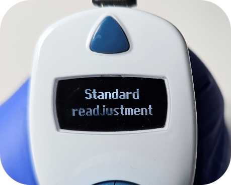
The standard readjustment utilizes a 3-point calibration (low, middle & high). Using the data collected in step 1, get an average value in microliters for each test volume.
Step 8:
Click the dispense button (the current setpoint value will flash) to modify the low point value and adjust to the calculated average value by turning the adjustment knob. Once the value is set, click the dispense button to lock in the value.
Step 9:
To move to the middle & high test points, turn the adjustment knob clockwise. Repeat the same process in step 8 for the middle and high averaged values.
Step 10:
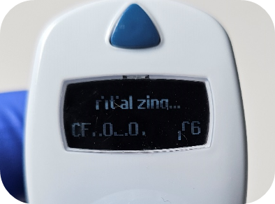
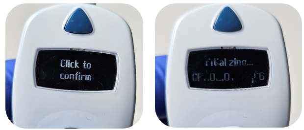
After all values are entered, turn the adjustment knob clockwise to “Click to confirm”. Click the dispense button. This will cause the pipette to restart.
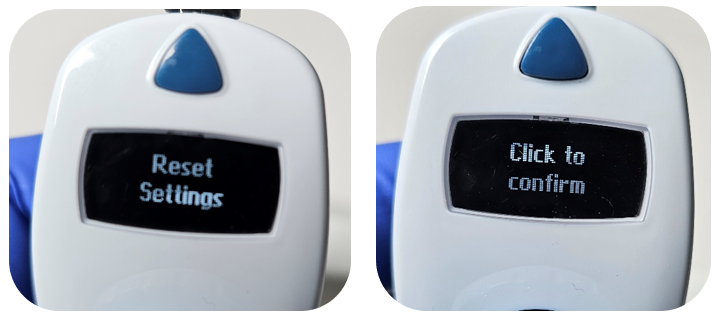
Note: There is an option to perform a factory reset of the calibrated values. To begin, complete steps 1 through 6. After completing step 6, turn the adjustment knob clockwise to select “Reset settings.” The prompt “Click to confirm” will appear on the screen. Press the dispense button to confirm and complete the factory reset.
Step 11:
Use the balance to check the pipette now that the adjustment has been made.
Disclaimer: Any action you take using the information on this website is strictly at your own risk. The information herein does not constitute professional advice and is general in nature. We make no warranty that this information will meet your requirements, be safe, accurate, or error-free. Pipette Supplies, Inc. is not responsible for any errors or omissions, any results obtained from the use of this information, or any loss or damage arising out of the use of this information. This site is for educational purposes only. Fair Use: Copyright Disclaimer under section 107 of the Copyright Act of 1976, allows for “fair use” for purposes such as comments, criticism, teaching, scholarship, news reporting, and research. Fair use is permitted by copyright statute that might otherwise be infringing.
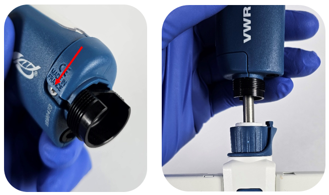
The process of removing, replacing, and reinstalling the battery for the Gilson Pipetman M & VWR Electronic(after market version of Pipetman M) requires great care, a high attention to detail, patience, and steady hands. Please dedicate a good work area with good lighting and space where small parts can be located should they pop/fly out during disassembly. Pipette damage and lost parts may occur if attention to detail is not maintained. Please proceed at your own risk.
GI F807007 – For newer Pipetman M pipettes with serial numbers from GD14021 (battery batch code 10-2010 / 11-2010 or later)
GI F807113 – For older Pipetman M pipettes with serial numbers from DL80001 to GD14020 (battery batch code 08-2009 and 05-2010)
The VWR Electronic models utilize the same battery as the newer style battery (GI F807007).
Recommend Supplies:
Flat-Head Screwdriver
Thin Needle nose pliers
Preliminary note: This disassembly process applies to both single and multichannel models, as they have an identical upper half of the pipette and attach to the ejector assembly in the same fashion.
Step #1:
Start by pushing down on the Pipetman M / VWR Electronic ejector button and unclip the tip ejector from the ejector assembly.
Step #2:
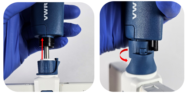
Unthread the connecting nut from the pipette body.
Step #3:
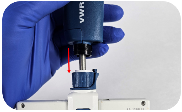
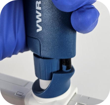
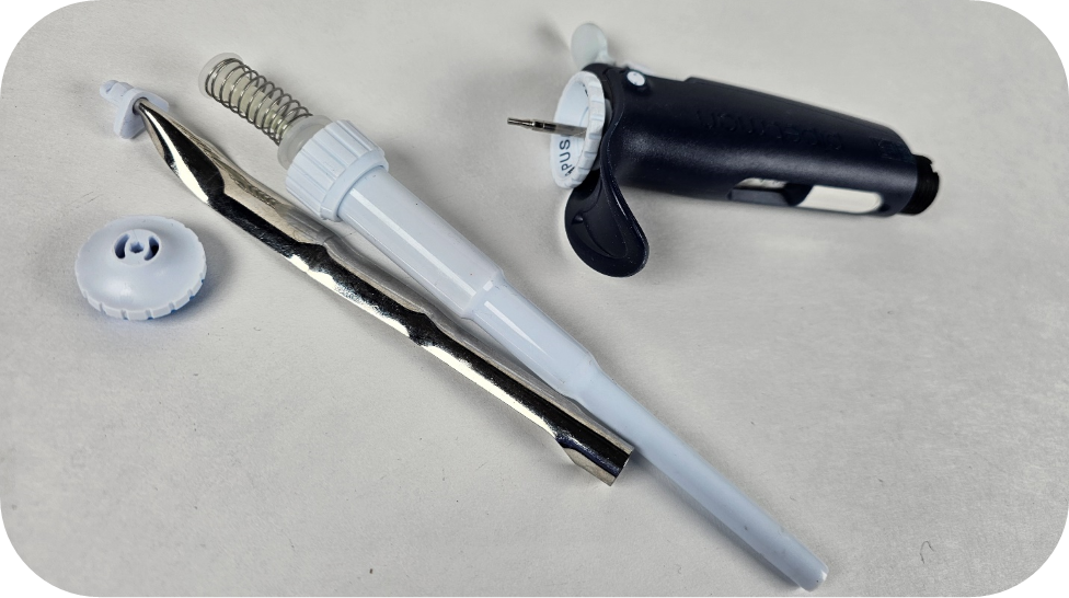
Gently pull down on the lower assembly to disconnect the lower assembly from the upper handle.
Note: The piston assemblies are magnetically attached to the spindle. In some cases —particularly with single channel models—the piston may not detach with the removal of the lower assembly. If this occurs, gently pull down on the piston assembly to remove it. To prevent damage, it is recommended to remove the piston/operating system before proceeding.
Step #4:
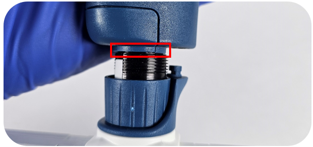
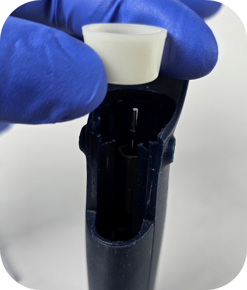
Some Pipetman M / VWR Electronic multichannel models have an O-ring located above the threads on the pipette body (see picture below for reference). The O-ring tend to dry out and crack over time. It is recommended to remove the O-ring as part of this repair process.
Note: Gilson does not replace these O-rings as part of their standard service.
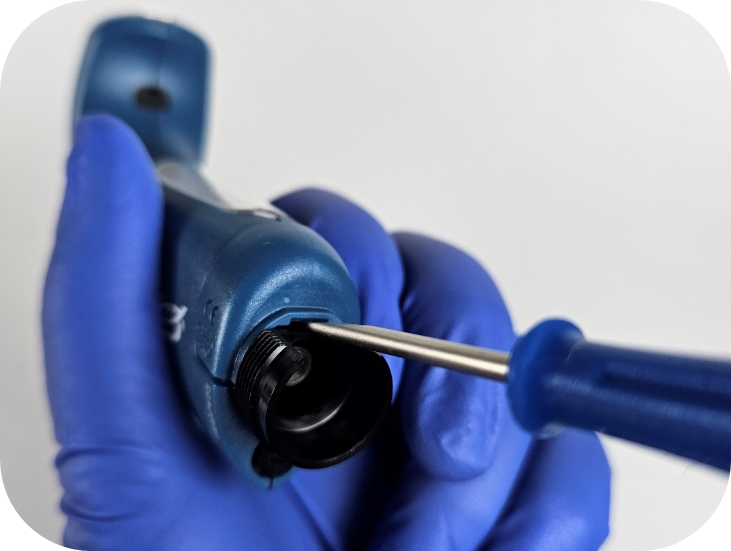
Step #5:
Using the flat-head screwdriver, pry up the battery door on the bottom of the handle (see picture below for reference).
Step #6:
Once the battery door is removed, carefully unplug the connector from the socket on the battery’s circuit board.
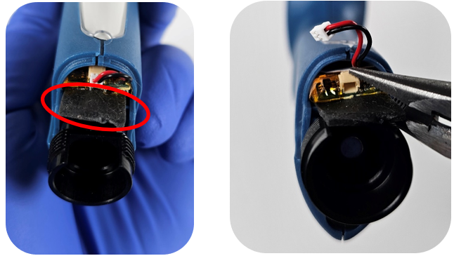
Note: It’s a good idea to connect the new battery first to confirm it resolves the issue before attempting to remove the old battery, as the new battery could be damaged during removal.
Step #7:
After the plug is disconnected, locate the tab on the back of the battery and slowly pull the battery out of the compartment.
Note: It’s common for the battery removal tab to break during this process. Needle-nose pliers can be helpful, as space in the battery compartment is limited. To remove the battery using pliers, position the two sides of the pliers around the socket on the circuit board and carefully pull the battery out.
Step #8:
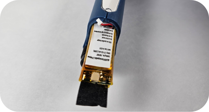
Install the new battery, ensuring that the side with the tab and socket is oriented correctly. Refer to the image below for the proper orientation of the battery.
Step #9:
Push the battery fully into the battery compartment, then reinsert the plug into the socket on the circuit board.
Step #10:
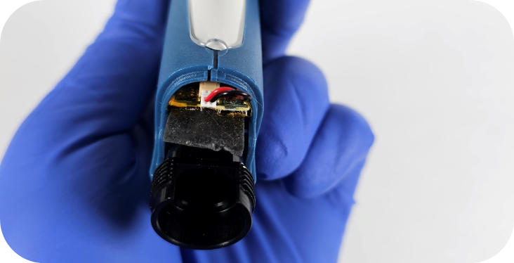
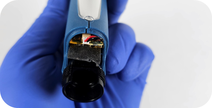
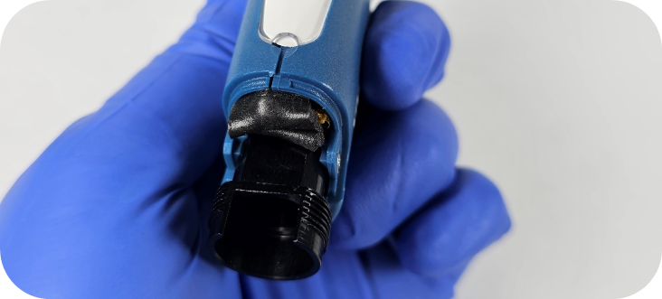
Before securing the battery door, make sure to lift the tab to ensure the door sits flat. In some cases, the flap can be tucked over the circuit board and into the top edge of the battery compartment, as shown in the image below.
Step #11:
Reattach the Pipetman M / VWR Electronic battery door, then reconnect the spindle to the piston (or to the operating system for multichannel pipettes).
Step# 12:
Slowly push the lower assembly toward the pipette body/handle. Once it is fully seated, tighten the connecting nut securely around it.
Step# 13:
Push down on the ejector button and reattach the tip ejector clip.
Note: When reattaching the lower assemblies of single channel pipettes, leaks can occur. It is important to ensure that all lower assembly parts are tightly secured.
Disclaimer: Any action you take using the information on this website is strictly at your own risk. The information herein does not constitute professional advice and is general in nature. We make no warranty that this information will meet your requirements, be safe, accurate, or error-free. Pipette Supplies, Inc. is not responsible for any errors or omissions, any results obtained from the use of this information, or any loss or damage arising out of the use of this information. This site is for educational purposes only. Fair Use: Copyright Disclaimer under section 107 of the Copyright Act of 1976, allows for “fair use” for purposes such as comments, criticism, teaching, scholarship, news reporting, and research. Fair use is permitted by copyright statute that might otherwise be infringing.
The process of removing, replacing, and reinstalling the Gilson Pipetman L counter assembly requires great care, high attention to detail, patience, and steady hands. Please dedicate a work area with good lighting and space where small parts can be located should they pop/fly out during disassembly. Pipette damage and lost parts may occur if attention to detail is not maintained. Please proceed at your own risk.
Pay special attention to the description as there are autoclavable and non-autoclavable parts in the counter link above. If a non-autoclavable counter is used in an autoclavable pipette, the counter will shrink around the adjustment screw if the pipette is autoclaved. The counter will become fused making it nearly impossible to disassemble/repair the pipette.
The autoclavable models can be identified by the following symbol on the pipette body:
Preliminary note: It is recommended to use the Pipetman L-specific tools, as they make repairs easier. We will provide instructions for completing the counter replacement without these tools. Please note that improper execution can cause marring or damage to the pipette, as all parts are made of plastic.
Step #1:
Start by removing the lower assembly, tip ejector, and button from the operating rod.
Note: If you do not have the Pipetman L calibration tool, it is recommended to adjust the pipette to the nominal volume prior to starting step #2.
Step #2:
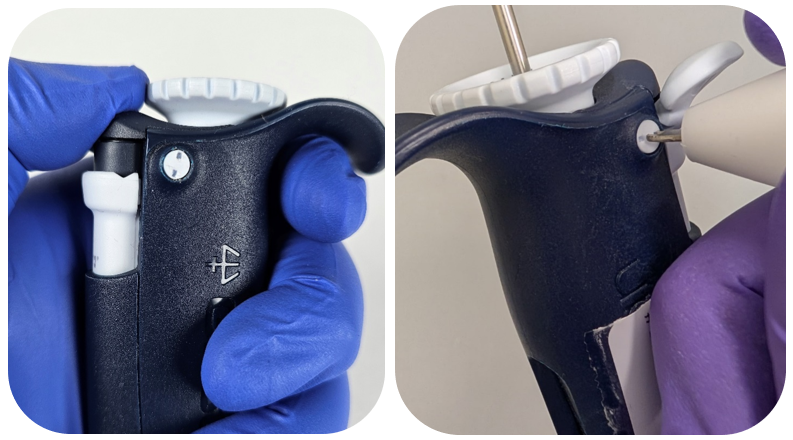
While pushing down on the blue part of the lock/unlock assembly, use the cap screw removal tool to turn the cap screw counterclockwise a quarter turn.
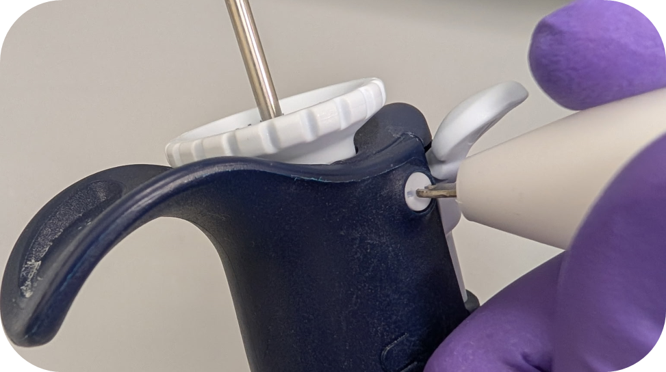
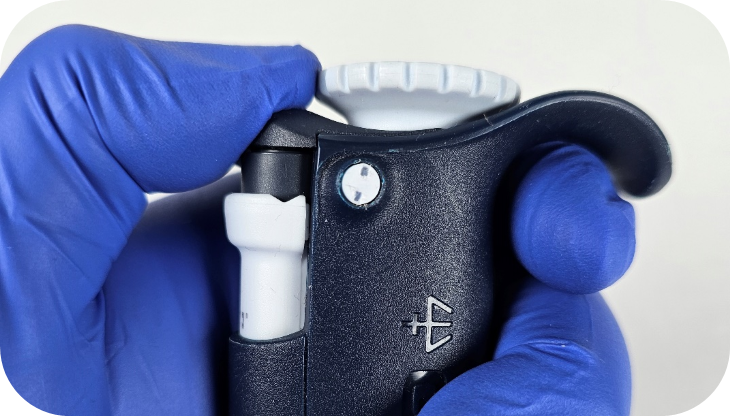
Ensure the cap screws are in the unlocked position as it is easy to turn them too far. Make sure the two indents make a vertical line as seen below:
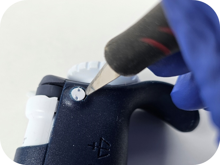
Note: If you have trouble getting the cap screws out, an Xacto knife can be used to flick/pry the cap screw out of the hole.
Step #3:
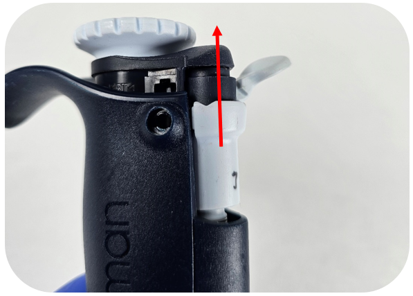
The lock/unlock assembly should be easily removed by pulling up on the assembly.
Step #4:
Now that the assembly is removed, invert the pipette. The bushing/collar around the adjustment screw should fall out.
Step #5:
Utilizing the Pipetman L calibration tool, secure the outer teeth of the tool to the flat sides of the adjustment screw.
Note: If you do not have a calibration tool you can re-seat the lock/unlock assembly and adjust the pipette beyond the nominal volume until there is enough of the adjustment screw exposed to turn it with your fingers.
Step #6:
Turn the Pipetman L calibration tool counterclockwise to remove the adjustment screw from the pipette. Once the adjustment screw disengages, pull the calibration tool straight out to remove the adjustment screw.
Step #7:
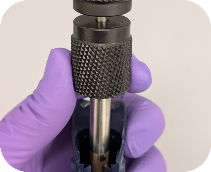
To remove the Pipetman L counter, insert the needle nose pliers into the adjustment screw hole in the counter and on the side containing the counter gears (circled in red below). It is important to have thin needle nose pliers to ensure you only grab the counter and not the two fins on either side of the counter gear assembly.
Note: The Gilson counter removal tool does not work for the Pipetman L and unfortunately, an updated tool is not available.
If you’re having trouble removing the counter with needle-nose pliers, you can also try using a flat-head screwdriver. After removing the adjustment screw, insert the flat-head screwdriver from the bottom of the pipette and secure it against the bottom part of the tab, pictured below. Once the screwdriver is in place, we recommend looking through the top to ensure the screwdriver is properly seated on the bottom of the counter’s tab.
While holding the screwdriver in place, gently tap or push the handle end against a flat surface. This process may take a few attempts, as the screwdriver can slip off the plastic tab. Take extra care to avoid damaging the internal threads of the pipette body when performing this variation.
Step #8:
Install the new counter by applying downward pressure using your thumb or a screwdriver. A tactile click will confirm that the counter is properly seated.
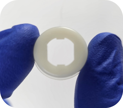
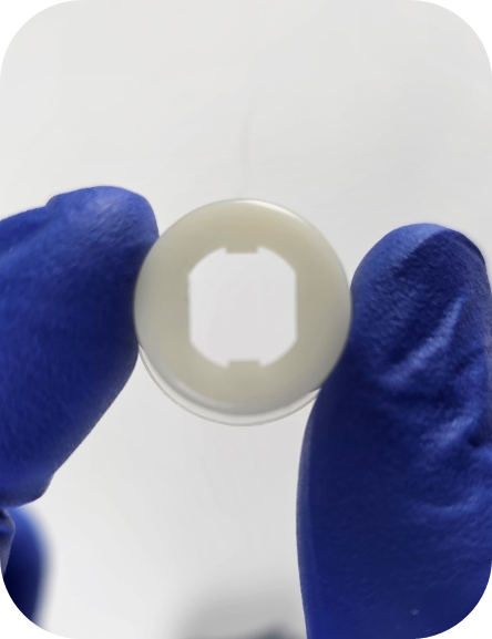
Note: On the very early non-autoclavable models of the Pipetman L, the spacer (opaque white ring) below the counter was not secured in by plastic tabs. If you are working on this model, the spacer will seat once the counter is snapped into place. For the autoclavable models, the spacer stays in place and should not be removed.
Step #9:
Attach the adjustment screw to the calibration tool and line up the tooth in the counter with the channel in the adjustment screw. To ensure the correct index value is set, it is important to not engage the adjustment screw in the threads below the counter until step #10 is completed.
Step #10:
Utilize the table below to set the index value of the Pipetman L counter. It is important to ensure the adjustment screw does not engage with the thread in body below the counter when setting the index.
Volumes
Index Value
10μL, 100μL, 1000μL, 10mL
135
2μL, 20μL, 200μL
235
5mL
670
Step #11:
Once the counter reads the value listed above, apply firm downward pressure and turn the adjustment screw/calibration tool clockwise.
Step# 12:
Reinstall the spacer, paying special attention to the orientation (flared side faces up) and alignment of the grooves on the adjustment screw. The spacer will slide down the adjustment screw to the counter when seated properly.
Step# 13:
Advice from our technical experts: Before installing the lock/unlock assembly, we recommend fully removing the ejector assembly O-ring. It tends to break down and breaks into pieces. These pieces can cause the ejector button to stick and potentially lead to counter damage.
Step# 14:
Install the lock/unlock assembly utilizing slight downward pressure. Note: Ensure the lock/unlock assembly sits flush with the top of the pipette body.
Note: If the lock/unlock assembly is not flush with the top edge of the pipette body it could be caused by two things. The lock/unlock assembly is not fully seated on the adjustment screw, and/or the adjustment screw needs to be lowered further into the body of the pipette.
Step #15:
While pushing down on the lock/unlock assembly, install the new cap screws and turn them clockwise a quarter turn. It is recommended by the manufacture to use new cap screws each time the pipette body is opened. It is possible to reuse cap screws, but it can be difficult to remove the cap screws multiple times.
Step #16:
Reattach the tip holder assembly, tip ejector, and button that was removed in step #1.
Step #17:
It is important to calibrate and verify the pipette is operating within manufacturer or customer-specific specifications before returning the pipette to service.
Disclaimer: Any action you take using the information on this website is strictly at your own risk. The information herein does not constitute professional advice and is general in nature. We make no warranty that this information will meet your requirements, be safe, accurate, or error-free. Pipette Supplies, Inc. is not responsible for any errors or omissions, any results obtained from the use of this information, or any loss or damage arising out of the use of this information. This site is for educational purposes only. Fair Use: Copyright Disclaimer under section 107 of the Copyright Act of 1976, allows for “fair use” for purposes such as comments, criticism, teaching, scholarship, news reporting, and research. Fair use is permitted by copyright statute that might otherwise be infringing.
The process of performing a Microman / Microman E / Pos-D calibration adjustment should always be the last option. Verifying that all other components are in good working condition and part replacement, as needed, should be done first. Pipette damage and lost parts may occur if attention to detail is not maintained. Please proceed at your own risk.
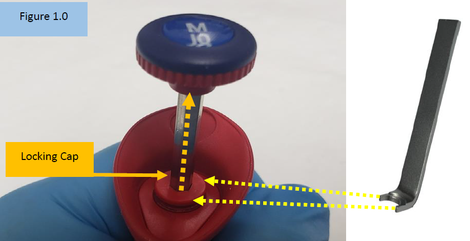
Required Microman Calibration Adjustment Tool: Locking Cap Lever Tool – GI F148172
NOTE: For illustration purposes, these instructions focus on the Gilson Microman. The instructions below and the locking cap lever tool can also be used with the Gilson Micronman E and Rainin Pos-D.
Insert the open end of the Locking Cap Lever Tool into the Microman locking cap. Figure 1.0. Once inserted into the locking cap, pry the locking cap upward.
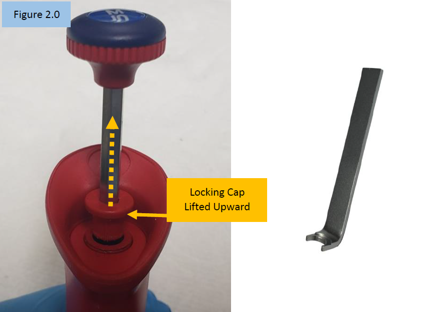
Step 2:
Notice the locking cap is now lifted upward and out of the pipette body.
CAUTION: With the locking cap now lifted upward, any movement of the adjustment knob will affect the calibration.
Step 3:
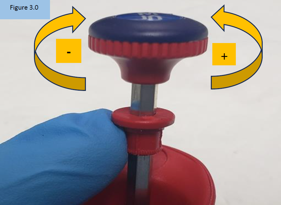
Rotate the adjustment knob:
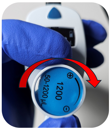
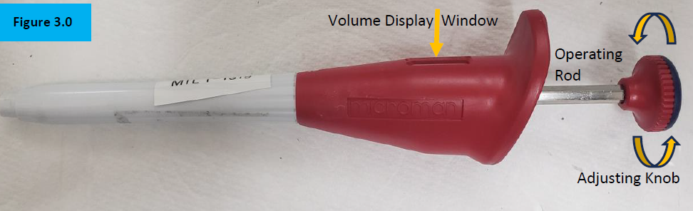
A. Counter-clockwise to increase the volume aspirated and dispensed ( + ) B. Clock-wide to decrease the volume aspirated and dispensed ( – ), Figure 3.0
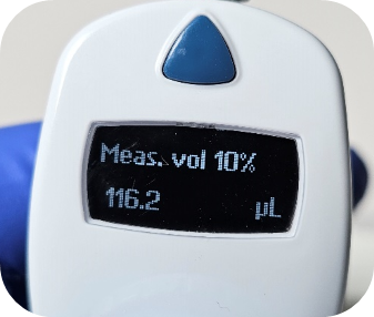
NOTE: Only turn the adjustment knob 1/8th of a turn at a time. Large turns will grossly affect desired results. For best results, it’s recommended to make adjustments at the 10% volume.
Step 4:
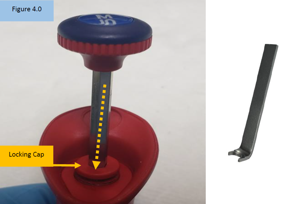
Insert the open end of the Locking Cap Lever Tool into the Microman locking cap. Push it back down into the body opening until it clicks back into place. Ensure it is fully in place. Figure 4.0.
Step 5:
Check the calibration adjustment made on a 4-5 place analytical balance. Repeat steps 1-5 if additional calibration adjustment is needed.
Disclaimer: Any action you take using the information on this website is strictly at your own risk. The information herein does not constitute professional advice and is general in nature. We make no warranty that this information will meet your requirements, be safe, accurate, or error-free. Pipette Supplies, Inc. is not responsible for any errors or omissions, any results obtained from the use of this information, or any loss or damage arising out of the use of this information. This site is for educational purposes only. Fair Use: Copyright Disclaimer under section 107 of the Copyright Act of 1976, allows for “fair use” for purposes such as comments, criticism, teaching, scholarship, news reporting, and research. Fair use is permitted by copyright statute that might otherwise be infringing.
The process of inspecting, performing preventive maintenance, and replacing/reinstalling parts on the Gilson Microman requires great care. A high attention to detail, patience, and steady hands are required. Please dedicate a good work area with good lighting and space where small parts can be located should they pop/fly out during disassembly. Pipette damage, affected calibration, and lost parts may occur if attention to detail is not maintained. Please proceed at your own risk.
To review before Gilson Microman disassembly:
These instructions are compatible with the Gilson Microman, not the Microman E.
Microman Replacement parts, including the parts listed in this post, can be found here.
External pipette and parts familiarity (Figure 1.0):
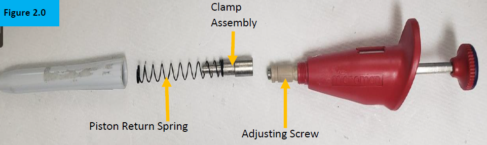
Internal pipette and parts familiarity (Figure 2.0):
Disassembly Process
Step 1:
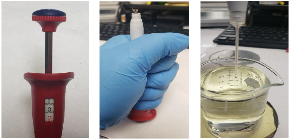
Wind the adjusting knob so that the nominal volume (100%) is displayed in the volume window. Figure 3.0.
NOTE: This will ensure the internal adjusting screw is mostly protected inside of the pipette body prior to disassembly and preventive maintenance.
Step 2:
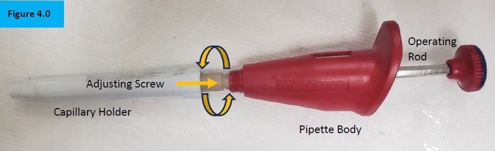
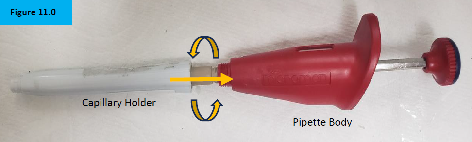
Unscrew the white colored capillary holder from the pipette body. Figure 4.0.
NOTE: Notice the tan/beige colored adjusting screw. This will be mostly visible if the volume is not adjusted to nominal prior to disassembly of the shaft. Take great care not to rotate or turn this component or calibration could be affected.
Step 3:
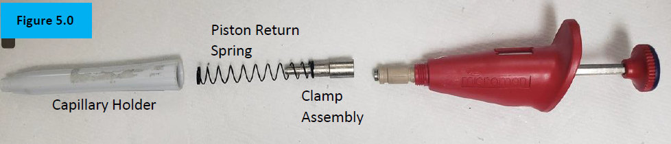
Separate the white capillary holder from the pipette body to expose the internal piston return spring and clamp assembly. Figure 5.0.
Step 4:
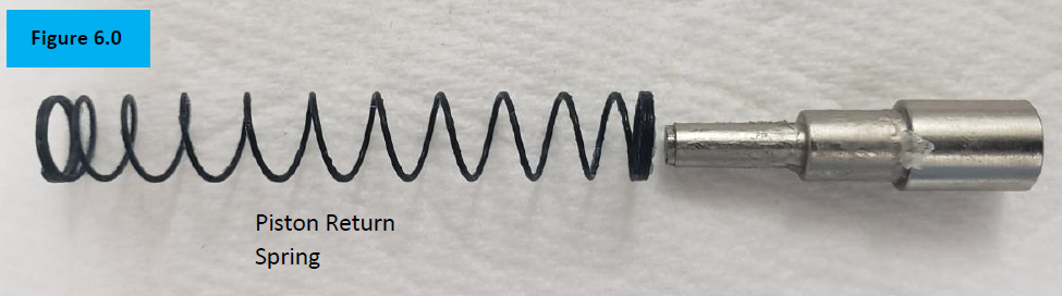
Inspect the piston return spring for cracks, rust, breaks. Replace as needed. Figure 6.0.
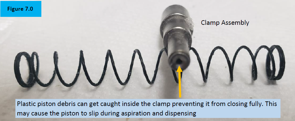
Inspect the clamp assembly for rust, chemical splash, and/or plastic piston debris that could be caught inside the clamp teeth. Figure 7.0.
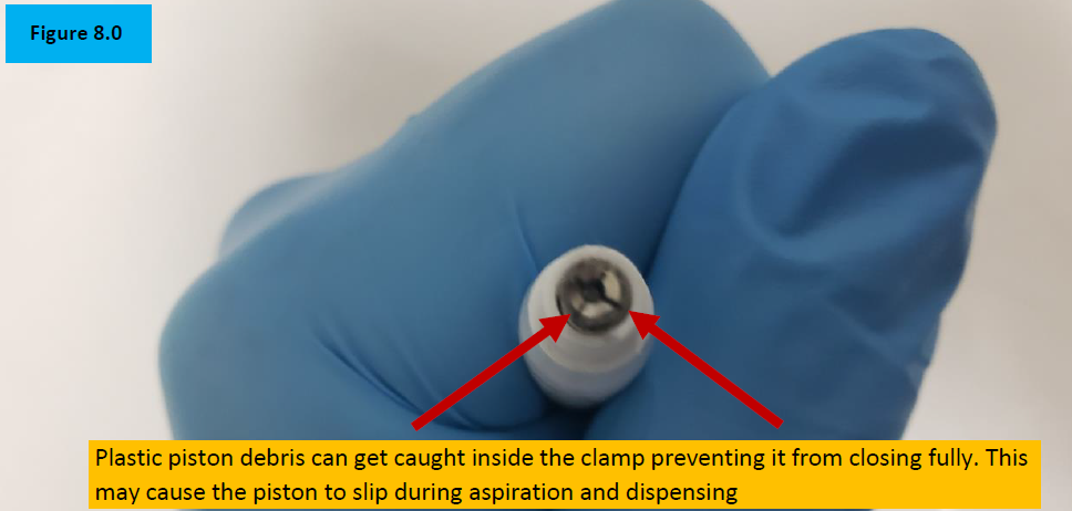
Inspect inside the clamp assembly for plastic shavings or debris that can prevent the clamp assembly from opening and closing fully. Replace as needed. Figure 8.0.
Reassembly Process
Step5:
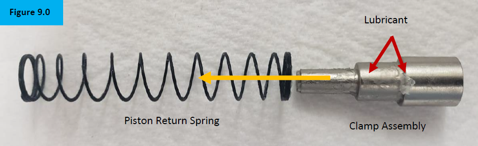
Insert the clamp assembly into the piston return spring. Figure 9.0.
NOTE: If desired, a small amount of lubricant can be applied to the outside of the clamp assembly to help provide a quieter piston return spring during aspiration and dispensing.
Step 6:
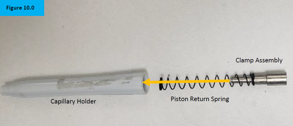
Slide the piston return spring and clamp assembly inside the capillary holder. Figure 10.0.
Step 7:
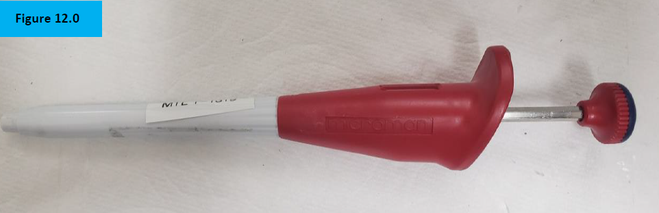
Screw on and attach the capillary holder to the pipette body. Figure 11.0.
Step 8:
Check for functionality, accuracy, and precision with Di Water and an appropriate analytical balance. Recheck work as necessary.
Disclaimer: Any action you take using the information on this website is strictly at your own risk. The information herein does not constitute professional advice and is general in nature. We make no warranty that this information will meet your requirements, be safe, accurate, or error-free. Pipette Supplies, Inc. is not responsible for any errors or omissions, any results obtained from the use of this information, or any loss or damage arising out of the use of this information. This site is for educational purposes only. Fair Use: Copyright Disclaimer under section 107 of the Copyright Act of 1976, allows for “fair use” for purposes such as comments, criticism, teaching, scholarship, news reporting, and research. Fair use is permitted by copyright statute that might otherwise be infringing.
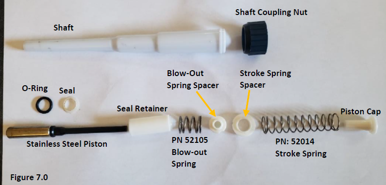
Gilson Pipetman Piston Return/Stroke Spring, Long: 52104 (The terms ‘return spring’ and ‘stroke spring’ refer to the same part)
Gilson Pipetman Piston Purge/Blow-out Spring, Short: 52105 (The terms ‘purge spring’ and ‘blow-out spring’ refer to the same part)
Pipetman Piston Assembly, P1000, P1000N, F250 to F1000: GI F123847
Step 1:
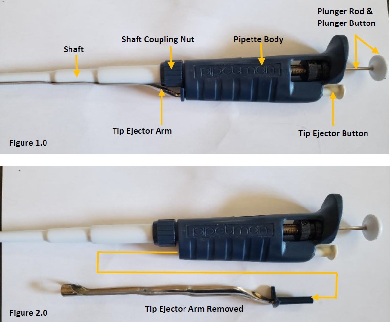
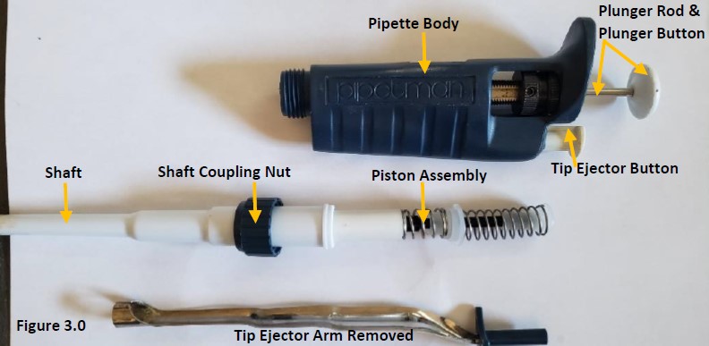
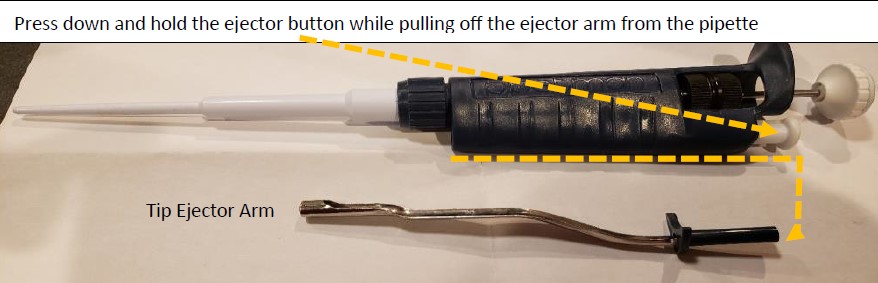
Press and hold the tip ejector button in the down position (figure 1.0) while detaching the tip ejector arm from the pipette body (figure 2.0). Figure 2.0 shows the tip ejector arm removed.
Step 2:
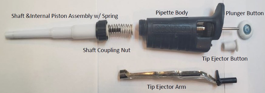
Carefully unscrew the coupling nut and shaft (figure 1.0) from the pipette body. There is an internal piston assembly and springs that may pop out when unscrewed and removed from the shaft (figure 3.0). Remove the piston assembly from the shaft and lay aside.
Step 3:
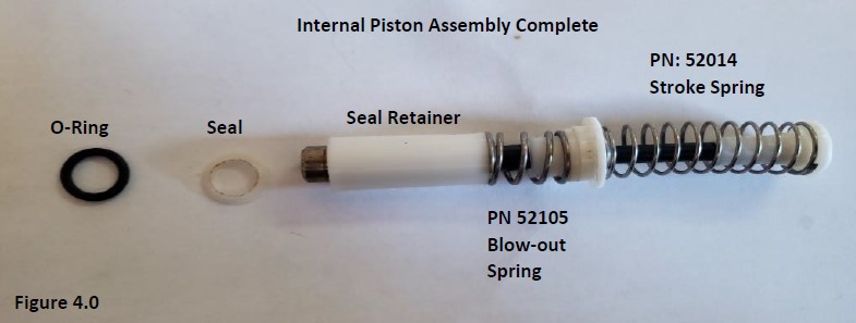
Remove the seal and o-ring from the piston and inspect for wear, dirt, and chemical splash. Lay them aside for replacement. Inspect the stainless-steel piston for wear, chemical splash, rust, pit mark or scratches. Replace piston assembly if needed. NOTE: A new piston assembly (GI F123847) includes a return spring.
Step 4:
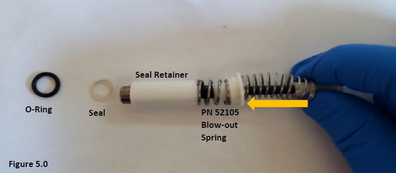
To replace the return spring (52104), press in and hold to collapse the spring (figure 5.0).
Step 5:
With the return spring still collapsed, firmly pull off and remove the piston cap from the piston stem and lay aside. Allow the return spring to relax and return to normal length (figure 6.0).
Step 6:
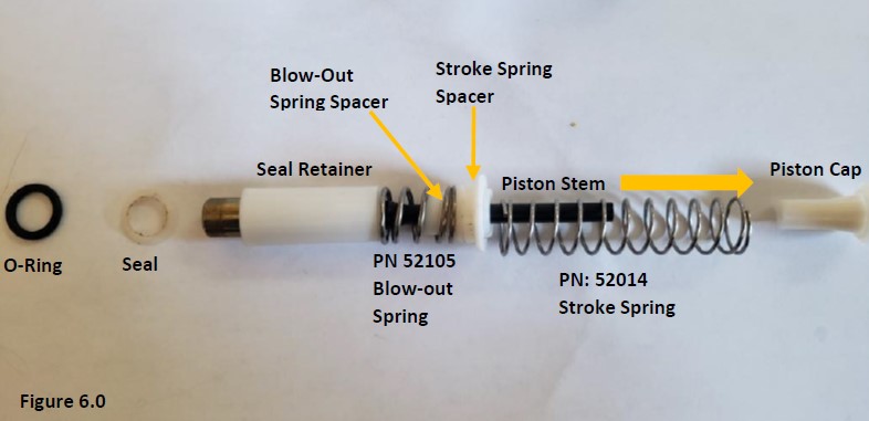
In figure 7.0, the piston cap, return spring, return spring spacer, purge/blow-out spring spacer, purge spring (52105), seal retainer, stainless steel piston, seal, and o-ring are shown in order and orientation for reassembly.
Step 7:
Install and slide the stainless-steel piston into the seal retainer.
Step 8:
Re-install or install a new blow-out/purge spring (52105) onto the seal retainer.
Step 9:
Install a new purge spring spacer onto the purge spring, then install & seal the new return/stroke spring spacer onto the purge spring spacer & return spring.
Step 10:
Install the piston cap back onto the piston stem. See figure 4.0 for correct assembly.
Step 11:
Insert piston assembly into the shaft (figure 3.0).
Step 12:
Screw the shaft with the shaft coupling nut back onto the pipette body (figure 2.0). Final assembly should look like figure 1.0.
Step 13:
After reassembly, allow the pipette to equilibrate for at least 60 minutes then confirm accuracy and precision on a 4-place balance. Re-check work if needed.
Disclaimer: Any action you take using the information on this website is strictly at your own risk. The information herein does not constitute professional advice and is general in nature. We make no warranty that this information will meet your requirements, be safe, accurate, or error-free. Pipette Supplies, Inc. is not responsible for any errors or omissions, any results obtained from the use of this information, or any loss or damage arising out of the use of this information. This site is for educational purposes only. Fair Use: Copyright Disclaimer under section 107 of the Copyright Act of 1976, allows for “fair use” for purposes such as comments, criticism, teaching, scholarship, news reporting, and research. Fair use is permitted by copyright statute that might otherwise be infringing.
The process of removing, replacing, and reinstalling the Pipetman Push Rod Ejector Assembly requires great care, a high attention to detail, patience, and steady hands. Please dedicate a good work area with good lighting and space where small parts can be located should they pop/fly out during disassembly. Pipette damage and lost parts may occur if attention to detail is not maintained. Please proceed at your own risk.
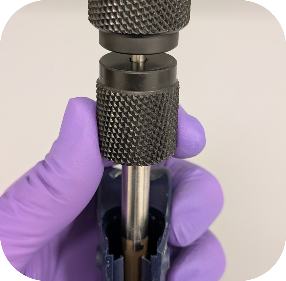
These instructions are ONLY applicable for Gilson Pipetman Single Channel and Multichannel Pipettes that use this ejector rod system: GI F144872. This includes Pipetman pipettes with tip ejectors that have the blue plastic piece.
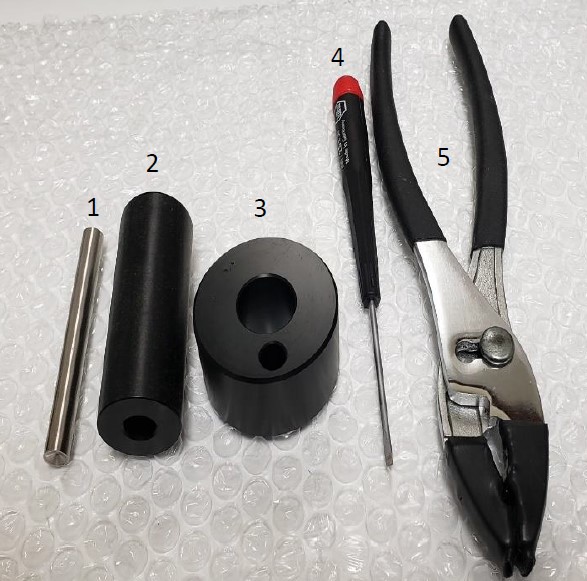
Recommended Service Tools
The following tools pictured here are strongly recommended to properly service, repair, or replace the Gilson Pipetman push rod ejector assembly.
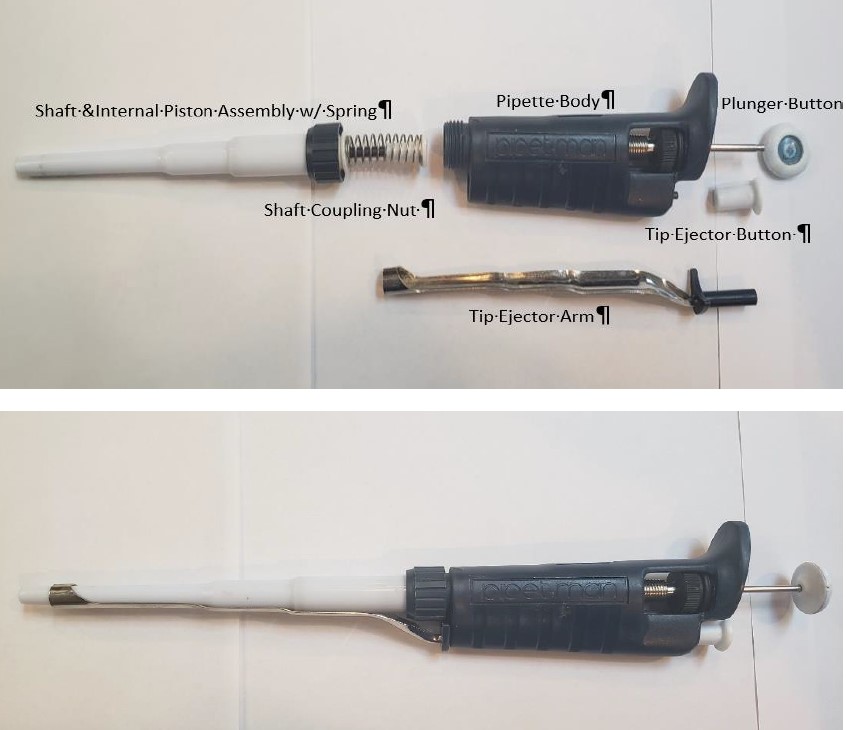
Remove the tip ejector arm from the pipette by pressing and holding down the white colored ejector button. With the button held down, pull off the tip ejector arm and lay aside for reassembly.
Step 2:
Unscrew the shaft coupling nut. Remove the shaft and internal piston assembly.
CAUTION: Be careful when unscrewing the coupling nut. The piston spring is under tension and may fly out with the piston assembly parts. Lay the piston assembly, shaft, and shaft coupling nut next to the tip ejector arm for reassembly later.
Step 2A:
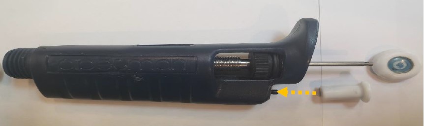
Pull off the plunger button and use the pliers with rubber nibs to remove the ejector button.
Step 3:
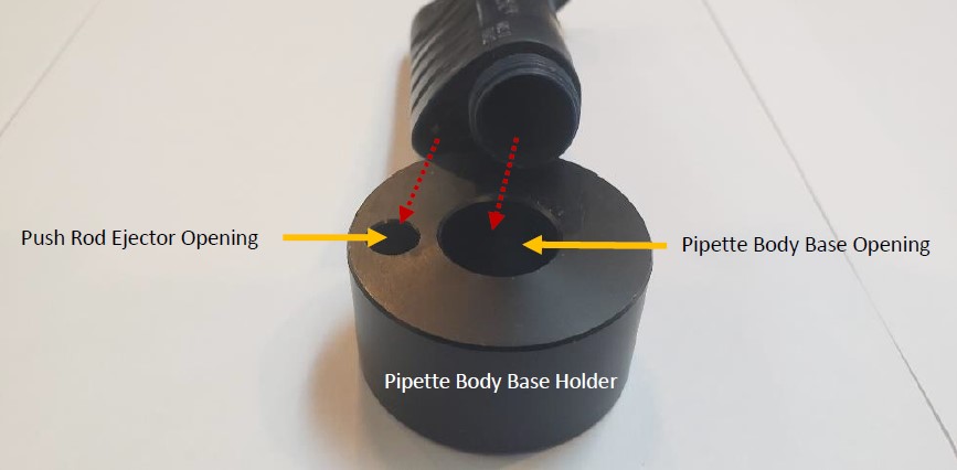
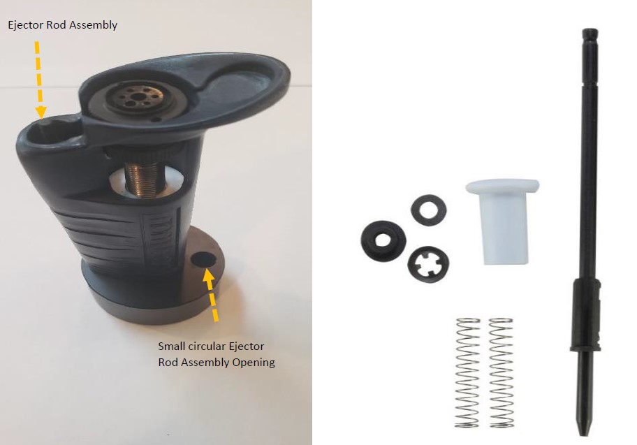
Notice the two circular openings of the platen holder, pictured below. The large circular opening is used to hold the pipette vertically in the holder The small circular opening is for the push rod ejector. Stand the pipette body in the platen holder.
Step 4:
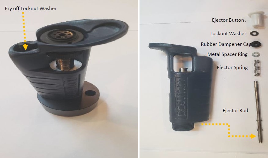
With a small-bladed flat head screwdriver, pry off the lock nut washer from the push rod ejector assembly. It may become damaged and will need to be replaced. Slide and remove all the ejector rod components from the bottom of the pipette body, as shown below.
NOTE: Based on the era of your Pipetman, some components may look slightly different.
Step 5:
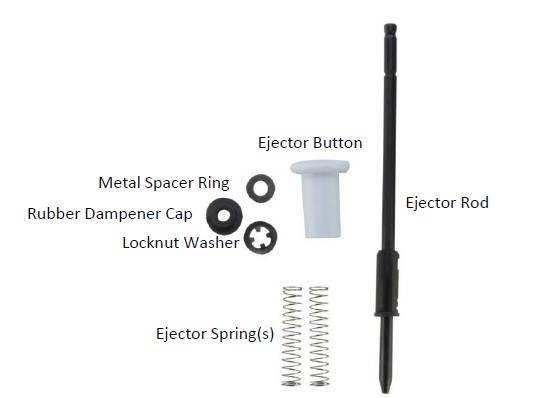
Based on the era of your Pipetman, the replacement push rod ejector assembly part number is likely GI F144872 and contains the parts as shown in the picture below.
Step 6:
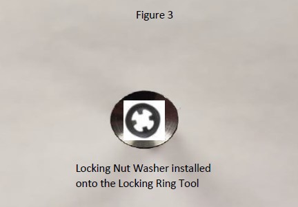
Place the replacement locknut washer onto the clip removal (locking ring) tool.
Step 7:
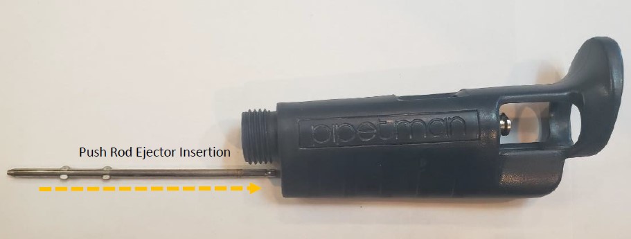
Fully Insert and hold the metal ejector rod assembly back into the pipette body through the bottom opening.
Step 8:
With the ejector rod inserted and held inside the body, place the pipette body onto the base holder as shown in the picture to the right. If done correctly, you will see the top of the ejector rod assembly sticking slightly out of the top of the pipette.
NOTE: Keep the small circular hole opening on the right side of the base and away from the ejector rod assembly for this process.
Step 9:
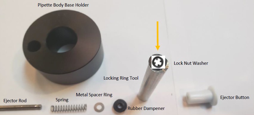
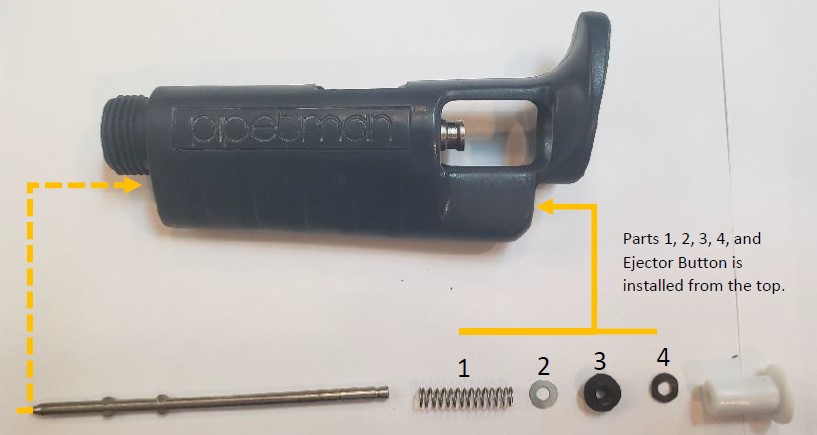
Install the replacement push rod ejector components onto the top portion of the push rod assembly in the order as shown in the picture below.
NOTE: #4 locknut washer will be installed onto the clip removal (locking ring) tool for installation.
Step 10:
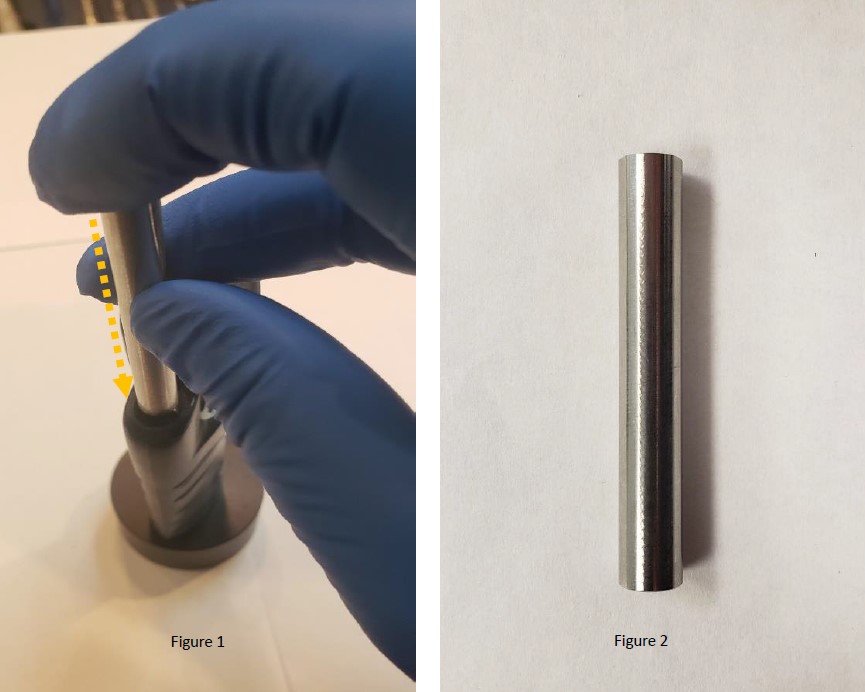
With the ejector rod inserted through the bottom of the pipette, and the spring, metal spacer ring, and rubber dampener inserted through the top of the pipette, place the locknut washer onto the locking ring tool. Figure 3.
Step 11:
As shown in figure 1, insert the clip removal (locking ring) tool face down into the push rod ejector rod, push the tool down to seat, and lock the locking ring onto the push rod ejector rod. If needed, tap the end of the locking ring tool with a rubber mallet to seat the locking ring into place. Remove the tool.
Step 12:
Install the tip ejector button back onto the ejector rod. Tap with a rubber mallet if needed.
Step 13:
Install the shaft and internal piston assembly back into the pipette body. Reattach the tip ejector arm to the pipette body. Test and recheck work if needed.
Disclaimer: Any action you take using the information on this website is strictly at your own risk. The information herein does not constitute professional advice and is general in nature. We make no warranty that this information will meet your requirements, be safe, accurate, or error-free. Pipette Supplies, Inc. is not responsible for any errors or omissions, any results obtained from the use of this information, or any loss or damage arising out of the use of this information. This site is for educational purposes only. Fair Use: Copyright Disclaimer under section 107 of the Copyright Act of 1976, allows for “fair use” for purposes such as comments, criticism, teaching, scholarship, news reporting, and research. Fair use is permitted by copyright statute that might otherwise be infringing.