Category: Gilson

  • Counter Assembly Instructions for Gilson Pipetman / Rainin Classic

    How to Remove and Install a New Counter Assembly for Gilson Pipetman with the Counter Disassembly/Assembly Tool

    In this post:
    Counter Removal Tool: PS 10002
    Gilson Counter Assemblies
    Pipetman Classic Replacement Parts: Single Channel

    NOTE: These instructions are not recommended for the Pipetman L. You can find Pipetman L Counter Assembly instructions here.

    Disassembly

    Step 1:

    Press and hold down the white colored tip ejector button. This will slightly lower the stainless-steel tip ejector arm and make it easier to remove. With a little force, carefully pull down on the tip ejector arm to detach and remove it from the pipette body. Lay aside for reassembly later.
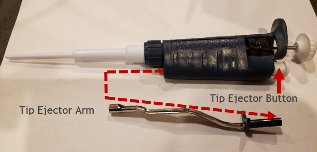
    Pipetman and tip ejector schematic
    Step 2:

    Carefully unscrew the shaft coupling nut from the pipette body.  

    CAUTION:  When the shaft coupling nut is removed from the pipette body, the internal piston assembly might forcefully pop out from inside the white colored shaft. Take great care so the internal piston assembly and components do not pop and fly out of the shaft, or you may be forced to locate and or replace the seal, O-ring, seal retainer, stroke spring, blowout spring, or piston, if lost. Internal piston assembly components may vary slightly based on pipette nominal volume size. Lay aside for later.
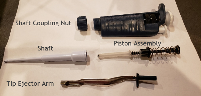
    Fully disassembled Pipetman. Labeled parts.
    Step 3:

    Turn the to adjust the pipette plunger button and volume display to nominal volume (i.e., 100% of the pipette volume)  

    Step 3A:

    Then gently rotate the volume increasingly past nominal volume until the plunger button and volume display will not rotate further. STOP and do not force the volume turning further. Usually this occurs when the friction ring contacts the top portion of the pipette body.  

    Step 3B:

    Remove the plunger button from the pipette by pulling upward and away from the plunger rod. Lay aside for later.
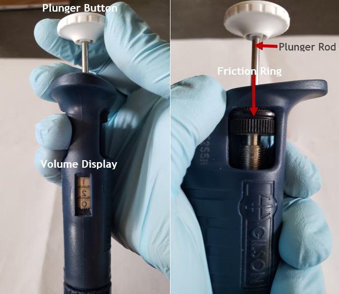
    Image demonstrating the plunger button removal
    Step 4:

    Insert bent nose pliers into the two outer most holes on the black colored micro bolt and continue to rotate the micro bolt in an increasing manner until it can be removed and pulled out from the pipette body. Lay aside for reassembly later.

    NOTE: the bent nose pliers will provide the extra torque needed to allow the micro bolt and friction ring to be removed from the pipette body.

    COMMENT: If desired, you may cut off the plastic or rubber friction ring from the micro bolt with a razor blade prior to Step 3A. This means you will need to replace the friction ring with a new one, prior to reassembly. If the friction ring is not cracked or brittle, replacement is usually not needed.

    Photo Comments (below): The micro bolt was already removed from the pipette body to show the outer most holes easier for viewing purposes.
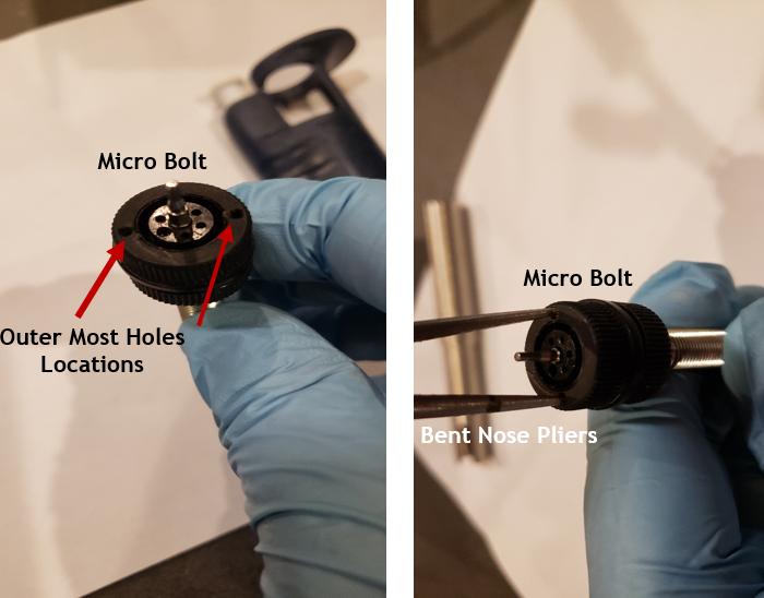
    Microbolt removed from the pipette body to show outer holes

    Counter Removal Tool Illustration (PS 10002): Shown to identify each end for intended use during removal and installation

    Step 5:

    Insert the slightly thinner and contoured end of the counter removal tool into the pipette body opening.

    CAUTION: if the counter removal tool does not insert easily into the body opening and feels like it is being forced into the body, stop! Please do not force the tool into the body or it may get stuck, damage the pipette body, and require excessive force to remove the tool. Based on the age of the pipette, there is a possibility that the body opening may have shrunk slightly due to properties of the materials, environmental, age of the instrument, etc.
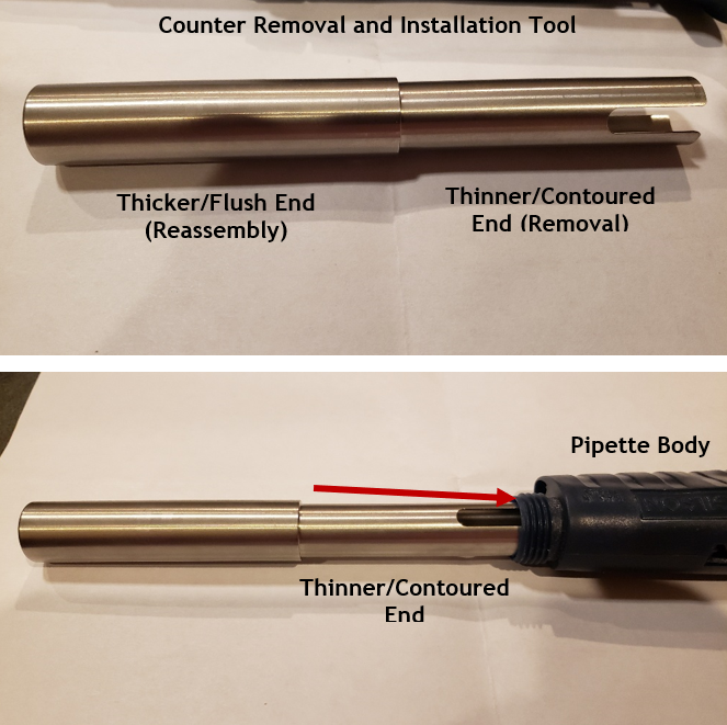
    Counter removal and calibration tool. Shown being inserted into the pipette body.
    Step 6:

    With the thinner contoured end fully inserted into the pipette body opening, gently tap or bang the end of the counter removal tool vertically onto a hard surface such as a table or bench top 2-3 times to unseat the counter assembly from the pipette body. This should be done vertically as shown.
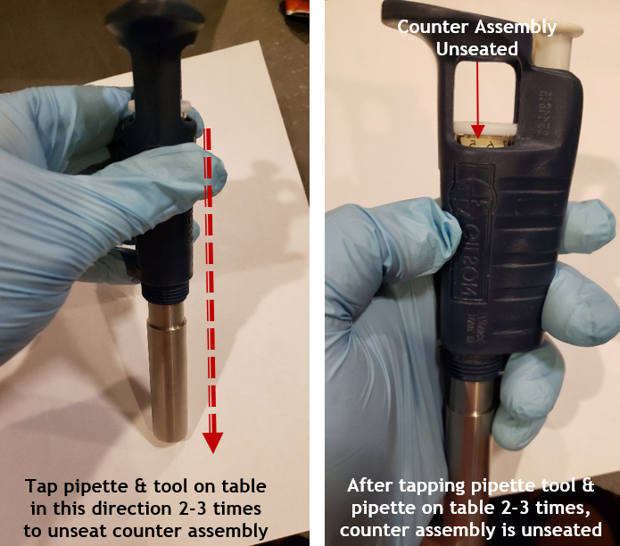
    Counter assembly tool being used to remove/dislodge the counter assembly
    Step 7:

    Remove the counter assembly tool from the pipette body and lay aside. Then, lift and remove the counter assembly out of the top of the pipette body.
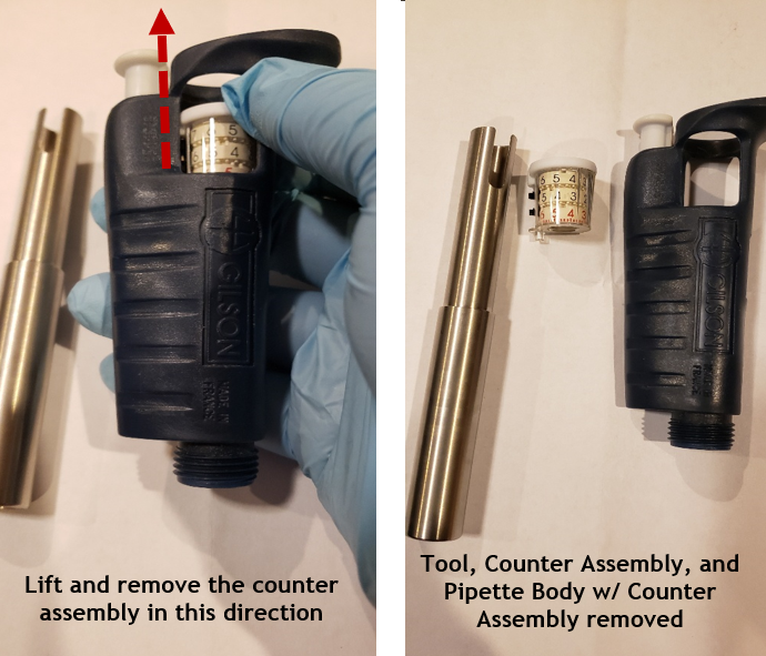
    Removing the counter assembly and the aftermath of the parts

    New Counter Assembly, Installation, and Pipette Reassembly

    Step 8 REASSEMBLY:  

    Carefully align and gently insert the new counter assembly into the top of the pipette body.

    Step 8A:

    Insert the thicker/flush end of the counter assembly tool on top of the new counter assembly and gently push the new counter assembly until it is seated properly and fully into the pipette body. Once the counter assembly is properly seated, remove the counter assembly tool.
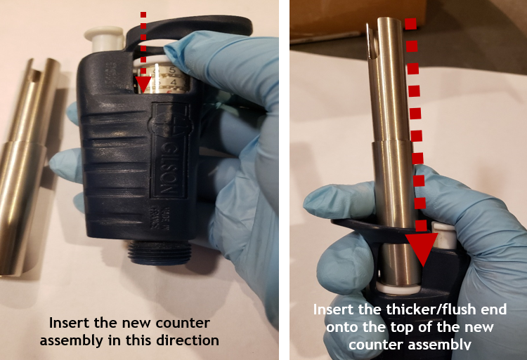
    Inserting the new counter assembly and using the counter assembly tool to press into place
    Step 9:

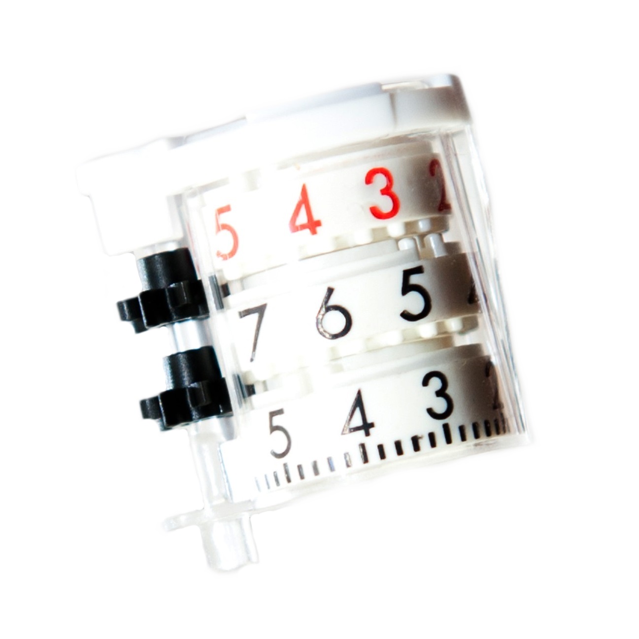
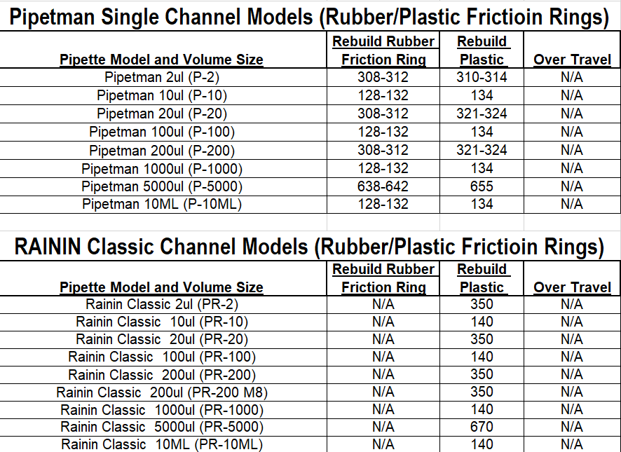
    Refer to Appendix 1 and obtain the proper counter assembly digits needed for insertion of the micro bolt assembly back into the pipette body based on the nominal size of the pipette (i.e., 200uL, 1000uL, etc.). Loosely insert the micro bolt into the counter assembly and gently rotate until the desired counter assembly digits appear in the volume display window.

    IMPORTANT: DO NOT ALLOW the micro bolt to seat into the pipette body until the desired digits are visible in the volume display window. This can be achieved by rotating the micro bolt and lifting it back out of the pipette and re-inserting it until the desired volume digits are visible in the volume display window.

    Example: If the desired digits are 134 for a 1000uL pipette, loosely insert the micro bolt, rotate the micro bolt without it catching in the body, and remove/repeat until the micro bolt displays 134 in the volume display window.

    Step 10:

    Align the micro bolt assembly with the white colored notched tab on the counter assembly. Once aligned, insert and push the micro bolt into the body fully until it stops/seated.
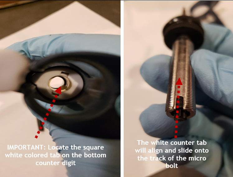
    Aligning the micro bolt assembly with the white colored notched tab on the counter assembly
    Step 11:

    Insert the bent nosed pliers into the two outer most holes on the micro-bolt.

    Step 11A:

    After insertion, press down and maintain force while turning the bent nosed pliers to seat the counter assembly fully back into the pipette body. Provide sufficient torque to allow the friction ring to seat back in place.

    Step 11B:

    When rotating the bent nosed pliers, the volume display digits will decrease as the micro bolt is seated back into place. Continue until the friction ring is below the top portion of the pipette body and the micro bolt can be rotated by hand and no longer with the pliers.

    Step 11C:

    Wind the pipette to the 10% volume.
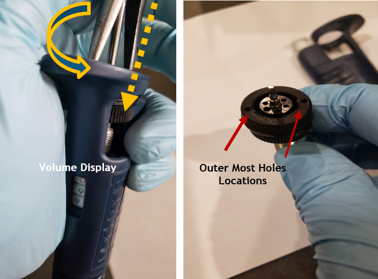
    Winding the volume display and locating micro bolt outer holes
    Step 12:

    Insert the piston assembly back into the shaft and place the coupling nut back on the shaft. Fully screw the shaft coupling nut back onto the pipette body.
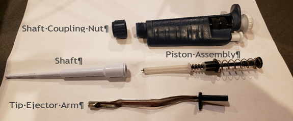
    Fully disassembled pipette with parts labeled
    Step 13:

    Press down on the tip ejector button and reattach the tip ejector arm to the pipette body.
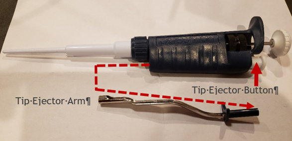
    Reinserting the tip ejector
    Step 14:

    Verify the desired accuracy and precision of the pipette is obtained on an appropriate balance. Calibration adjustments may be needed.
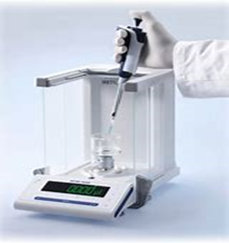
    verify the desired accuracy by using a scale
    Appendix 1: Counter Assembly Alignment Digit Settings
    Disclaimer: Any action you take using the information on this website is strictly at your own risk. The information herein does not constitute professional advice and is general in nature. We make no warranty that this information will meet your requirements, be safe, accurate, or error-free. Pipette Supplies, Inc. is not responsible for any errors or omissions, any results obtained from the use of this information, or any loss or damage arising out of the use of this information. This site is for educational purposes only.
    Fair Use: Copyright Disclaimer under section 107 of the Copyright Act of 1976, allows for “fair use” for purposes such as comments, criticism, teaching, scholarship, news reporting, and research.
    Fair use is permitted by copyright statute that might otherwise be infringing.
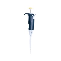
  • What model of Gilson Pipette do I have?

    This Gilson Pipette Legend aims to clarify the nomenclature of Gilson pipette codes and shorthand. Most codes are a mixture of a prefix letter, the max volume in microliters, and occasionally a suffix letter.

    Gilson Pipette Full NameGilson Code
    (Part# Prefix/Suffix)
    Example of
    SC 1000μl or 
    MC 1200μl, etc
    Pipetman Classic Single ChannelPP1000
    Pipetman Classic Fixed Vol Single ChannelFF1000
    Pipetman Concept MultichannelCC300
    Pipetman G Single ChannelP_GP1000G
    Pipetman L Single ChannelP_LP1000L
    Pipetman L Fixed Vol Single ChannelF_LF1000L
    Pipetman L MultichannelP(8 or 12)x(Vol)LP8x300L or P12x300L
    Pipetman M Single ChannelP_MP1200M
    Pipetman M MultichannelP(8 or 12)x(Vol)MP8x300M or P12x300M
    Pipetman Neo Single ChannelP_NP1000N
    Pipetman Neo MultichannelP(8 or 12)x(Vol)NP8x200N or P12x200N
    Pipetman P Single ChannelP or FP1000, F1000
    Pipetman Ultra Single ChannelUU1000
    Pipetman Ultra MultichannelU8/U12-U8-300, U12-300
    Microman Positive DisplacementMM1000
    Microman E Positive DisplacementM_EM1000E
    Distriman Repetitive Dispenser D-ManD 
    Autorep Repeating PipetAR 
    Gilson Pipetman L Pipette (P2L, P10L, P20L, ...)
    Pipetman L (P2L, P10L, P20L, …)

    Disclaimer: Any action you take using the information on this website is strictly at your own risk. The information herein does not constitute professional advice and is general in nature. We make no warranty that this information will meet your requirements, be safe, accurate, or error-free. Pipette Supplies, Inc. is not responsible for any errors or omissions, any results obtained from the use of this information, or any loss or damage arising out of the use of this information. This site is for educational purposes only.
    Fair Use: Copyright Disclaimer under section 107 of the Copyright Act of 1976, allows for “fair use” for purposes such as comments, criticism, teaching, scholarship, news reporting, and research.
    Fair use is permitted by copyright statute that might otherwise be infringing.
  • Pipetman L Ejector Maintenance

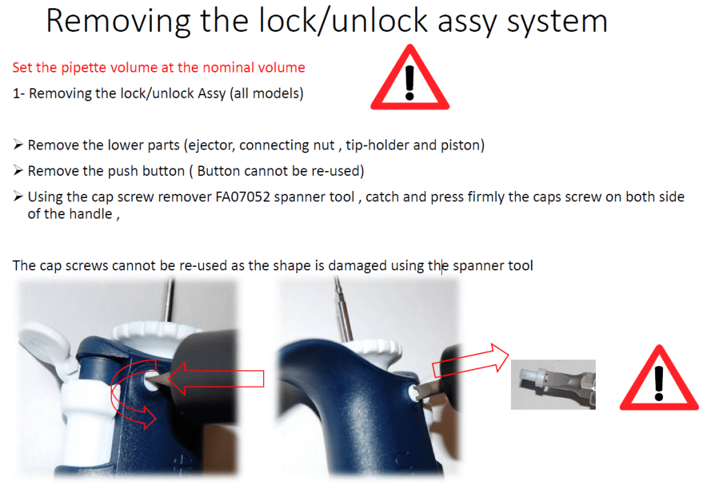
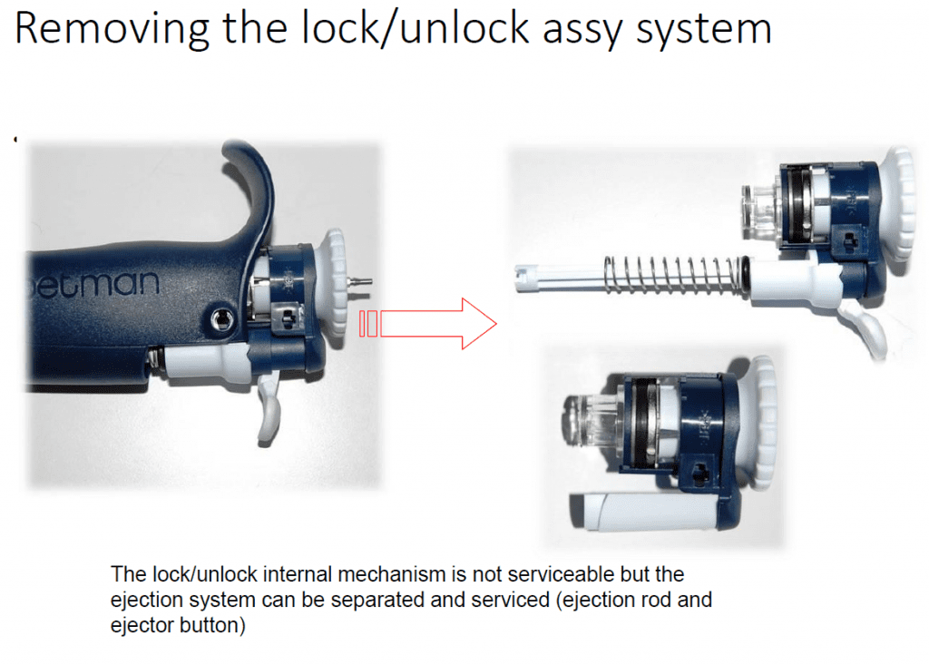
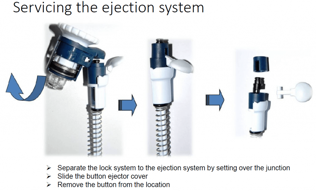
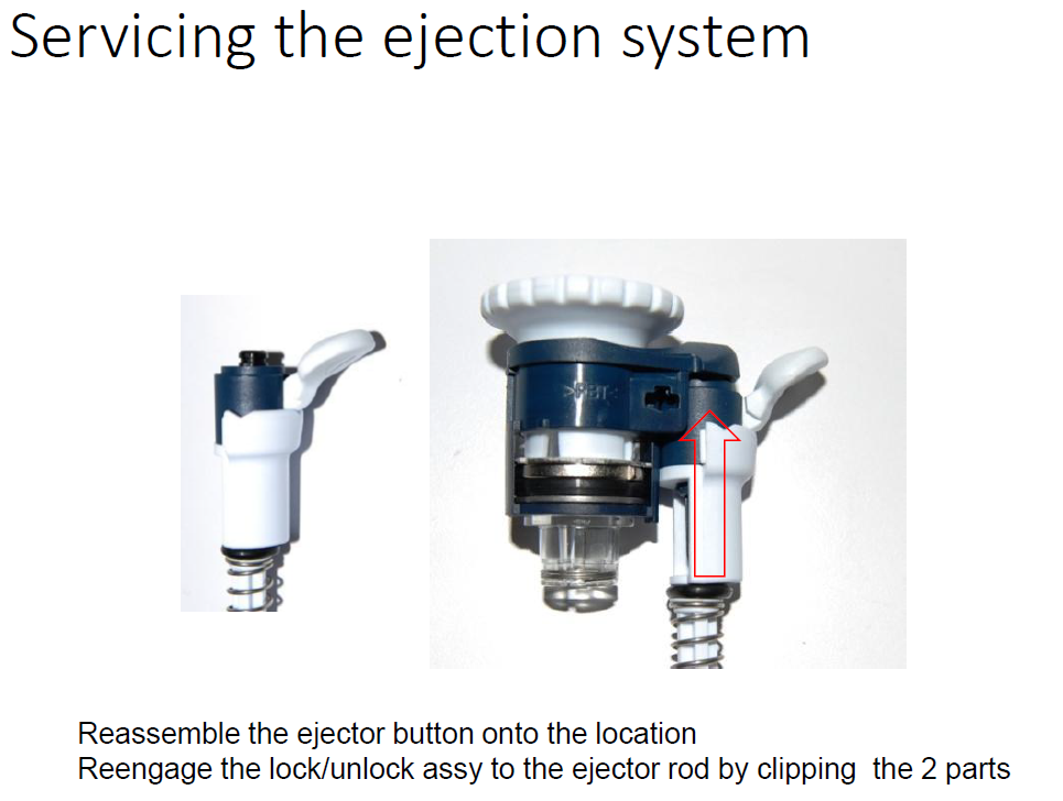
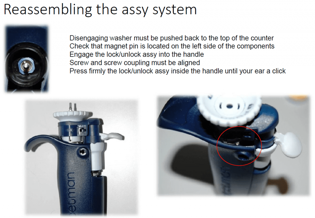
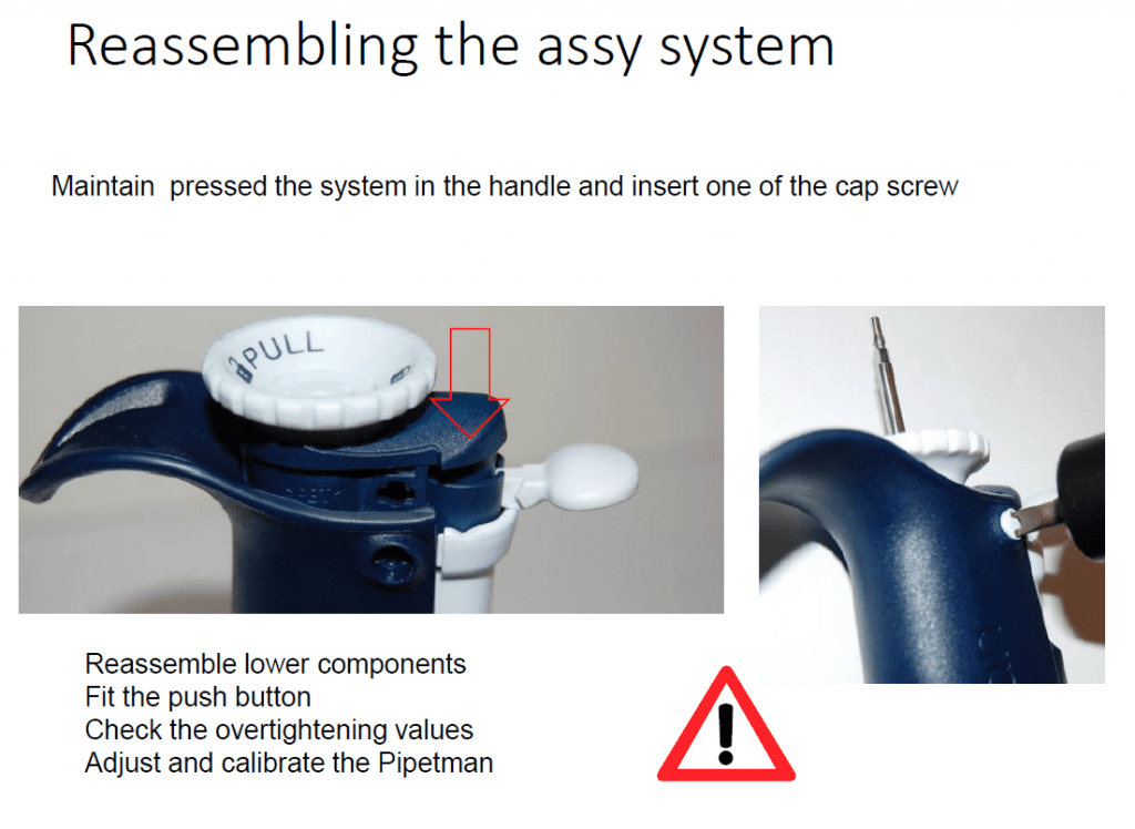
    Lock/Unlock Assembly Parts


    Disclaimer: Any action you take using the information on this website is strictly at your own risk. The information herein does not constitute professional advice and is general in nature. We make no warranty that this information will meet your requirements, be safe, accurate, or error-free. Pipette Supplies, Inc. is not responsible for any errors or omissions, any results obtained from the use of this information, or any loss or damage arising out of the use of this information. This site is for educational purposes only.
    Fair Use: Copyright Disclaimer under section 107 of the Copyright Act of 1976, allows for “fair use” for purposes such as comments, criticism, teaching, scholarship, news reporting, and research.
    Fair use is permitted by copyright statute that might otherwise be infringing.
  • Styles of Gilson Pipette Tip Ejectors

    Styles of Gilson Pipette Tip Ejectors:

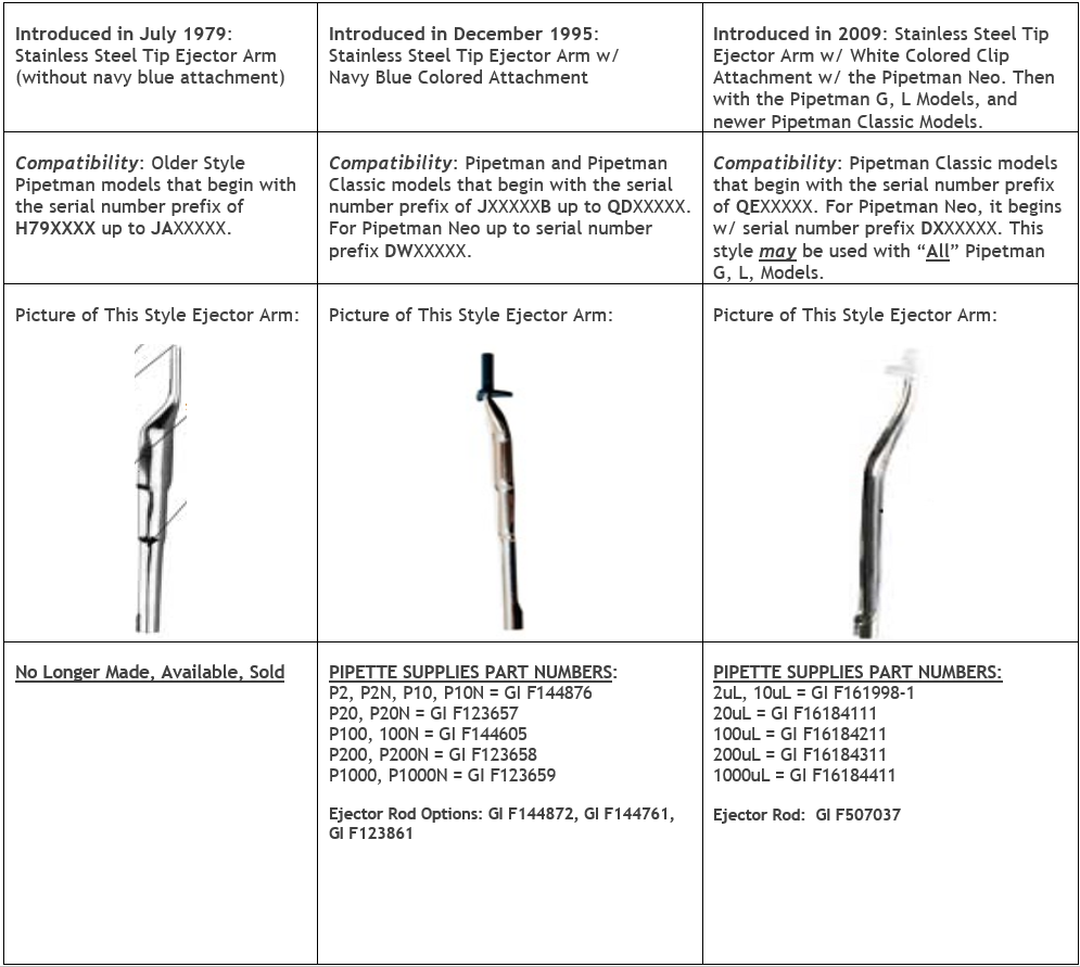
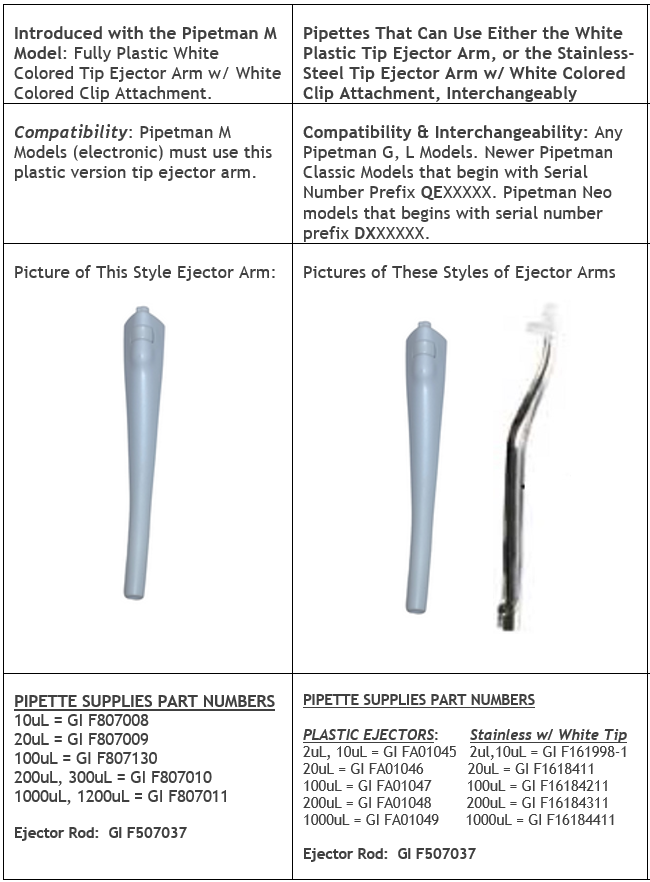
    Use this chart to confirm which style of tip ejectors are compatible with your Gilson pipettes. The following chart can be used for Pipetman Classic, G, L, M, and Neo(N) pipettes.

    Shop all Gilson Pipette parts (including tip ejectors) here.

    Gilson tip ejector differences chart
    Gilson tip ejector differences chart

    Disclaimer: Any action you take using the information on this website is strictly at your own risk. The information herein does not constitute professional advice and is general in nature. We make no warranty that this information will meet your requirements, be safe, accurate, or error-free. Pipette Supplies, Inc. is not responsible for any errors or omissions, any results obtained from the use of this information, or any loss or damage arising out of the use of this information. This site is for educational purposes only.
    Fair Use: Copyright Disclaimer under section 107 of the Copyright Act of 1976, allows for “fair use” for purposes such as comments, criticism, teaching, scholarship, news reporting, and research.
    Fair use is permitted by copyright statute that might otherwise be infringing.
  • Gilson Pipetman L Calibration Tool, Item # 28888

    Instructions to use the Pipetman L Calibration Tool. Link to product page: 28888

    This tool is for increasing or decreasing the pick-up volume during the calibration process.  Review and follow the Gilson publication, Verification Procedure for Accuracy and Precision.  Contact Us for a copy.

    Be sure that the sealing system of the pipette (piston, tip holder, seal and o-ring) is functioning properly.  The pipette liquid end must be leak-free.  If it is not, calibration will not be effective. 

    Printable Calibration Log
    Printable Calibration Stickers (for use with Avery 5960 labels)

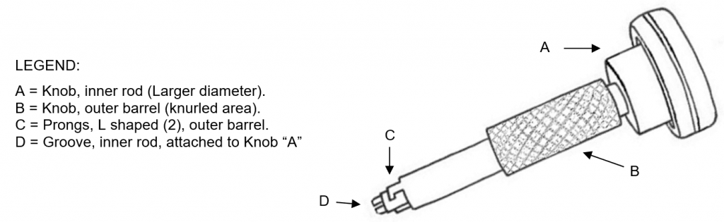
    Pipetman L Calibration Tool Schematic
    CALIBRATION INSTRUCTIONS:
    Step 1:

    Set the Pipetman L pipette to its minimum test volume according to the user manual (usually 10% of the nominal volume). 

    Step 2:

    Pre-rinse the tip. Dispense and weigh four individual samples. Determine the mean weight of the samples in micro-liters (µl). If the mean is not within accuracy limits, continue with the calibration.

    Step 3:

    Remove the plunger button from the pipette by pulling it straight up.  Push the volume control disc down to the lock position.

    Step 4:

    Insert the two prongs, C, of the Pipetman L calibration tool into the two slots of the center access button of the volume control disc. Rotate the tool counterclockwise about 15 degrees and pull out. The center access button will come out loaded on to the two prongs. Hold the button in one hand and rotate the tool in clockwise direction to disengage and unload the button from the tool.

    Step 5:

    Holding on to the large knob A and letting the outer barrel with the knob B slip down on its own weight, slide the tool over the plunger rod and let it go inside the pipette body as far as it can on its own weight.

    Step 6:

    While pressing down VERY slightly, rotate the knob B.  The two prongs of the knob B will engage with the square part of the calibration mechanism of the pipette in less than 45 degree of rotation.  

    Step 7:

    Rotate the large knob A without pressing down.  The groove C of the inner rod will fit over the inner member of the calibration mechanism.

    Step 8:

    To increase the pick-up volume, hold the knurled knob B firmly without letting it move and rotate the large knob A in counter clock direction; to decrease the pick-up volume rotate the knob A in clockwise direction.  Rotate ONLY about half turn at a time and re-check the mean weight as done in step 2.

    NOTE:  You do not need to put back the center access button into the volume control disc at this stage, just replace the plunger button making sure that the flats of the plunger button align with the flats of the plunger rod.

    Step 9:

    Check the pipette at the 10% volume as done in step 2.  If the pipette is within the specification, continue with the next step.  If not, return to step 2.

    Step 10:

    Set the pipette to its maximum volume and perform the calibration test.  If the instrument is within accuracy limits, it has been calibrated successfully.  If it is outside the accuracy limits, return to step 2 and repeat the process.

    Step 11:

    Remove the plunger button again.  Load the center access button on to the two prongs C of the Pipetman L calibration tool, insert the button in its place and turn the tool about 15 degrees clockwise. The button will lock in the volume control disc.  Pull out the tool and install the plunger button on the plunger rod.

    “Pipetman” is a registered trademark of Gilson, S.A.S.

    Disclaimer: Any action you take using the information on this website is strictly at your own risk. The information herein does not constitute professional advice and is general in nature. We make no warranty that this information will meet your requirements, be safe, accurate, or error-free. Pipette Supplies, Inc. is not responsible for any errors or omissions, any results obtained from the use of this information, or any loss or damage arising out of the use of this information. This site is for educational purposes only.
    Fair Use: Copyright Disclaimer under section 107 of the Copyright Act of 1976, allows for “fair use” for purposes such as comments, criticism, teaching, scholarship, news reporting, and research.
    Fair use is permitted by copyright statute that might otherwise be infringing.
  • Pipetman Calibration Wrench, Item # 27777

    Pipetman Calibration Instructions:

    Printable Calibration Log
    Printable Calibration Stickers (for use with Avery 5960 labels)

    Link to product page: 27777

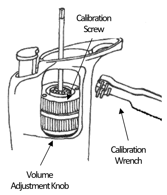
    This wrench is used for increasing or decreasing the pick-up volume during the calibration process on Pipetman versions that have 6 holes on the top of the Calibration Screw. 

    Review and follow the Gilson publication, Verification Procedure for Accuracy and Precision. Contact Us for a copy.

    Be sure that the sealing system of the pipette (piston, tip holder, seal and o-ring) is functioning properly.  The pipette liquid end must be leak-free.  If it is not, calibration will not be effective. 

    Pipetman calibration scehmatic

    CALIBRATION:

    Step 1:

    First, set the pipette to its minimum test volume according to the user’s manual (usually 10% of the nominal volume). 

    Step 2:

    Pre-rinse the tip, dispense and weigh four individual samples. Determine the mean weight of the samples in micro-liters (µl). If the mean is not within accuracy limits, continue with the calibration.

    Step 3:

    Hold the Volume Adjustment Knob to prevent it from turning.  Place the 5 prongs of the wrench into 5 of the 6 holes on the top of the Calibration Screw, which is located inside the Volume Adjustment Knob.

    Step 4:

    To reduce pickup volume:  Turn slightly clockwise.
    To increase pickup volume:  Turn slightly counterclockwise.

    Step 5:

    Remove the calibration wrench. 

    Step 6:

    After completing these adjustments, check the instrument at 10% of nominal volume as described in step 1. If the pipette is within specification at 10% nominal value, continue to the next step. If not, return to step 1 and perform the procedure again until the instrument is within specification limits.

    Step 7:

    Lastly, set the pipette to its maximum volume and then perform the calibration test. If the instrument is within accuracy limits, then it has been calibrated successfully. If it is outside of the accuracy limits, return to step 1 and repeat the process.

    “Pipetman” is a registered trademark of Gilson, S.A.S.

    Disclaimer: Any action you take using the information on this website is strictly at your own risk. The information herein does not constitute professional advice and is general in nature. We make no warranty that this information will meet your requirements, be safe, accurate, or error-free. Pipette Supplies, Inc. is not responsible for any errors or omissions, any results obtained from the use of this information, or any loss or damage arising out of the use of this information. This site is for educational purposes only.
    Fair Use: Copyright Disclaimer under section 107 of the Copyright Act of 1976, allows for “fair use” for purposes such as comments, criticism, teaching, scholarship, news reporting, and research.
    Fair use is permitted by copyright statute that might otherwise be infringing.
  • Gilson Pipetman Counter Assembly Realignment

    Ever needed to repair a Pipetman counter assembly?   

    For Pipetman G, Neo, and Classic:

    First, determine what necessitates the repair.  If one of the propelling gears has a broken tooth, the repair is not so simple. These repairs should only be attempted by a service provider.

    If the malfunction is due to the counter assembly being out of alignment because:

    • One or more of the rotating wheels has jumped off the track (from over winding)
    • The pipette had a trauma (possibly falling too many times on the floor)
    It can be easily repaired by following procedure:

    Unwind or start rotating the counter assembly towards its highest reading (1000ul towards 1000 etc.) either holding from the area where the friction ring is, or just rotating the plunger button (depending on the Pipetman model). When the knob with the friction ring reaches the upper end of the pipette body, it will require extra force to turn and may require pliers. Rotating past that point, you will need to add the “pulling out” motion to the rotating motion. At a certain point, the micro-bolt (the one with threaded circumference and a groove on its length) will freely come out.

    Look inside the cavity where the micro-bolt came out. There should be a white tab protruding from the inside diameter of the rotating rings that bear the numbers on them which you read in the counter window.  With a very thin screwdriver or extended forceps, turn the tab clockwise or counter clockwise to reach the following readings in the counter window (it may take many turns):

                Models P10, P100, P1000, P10ML = 130 – 133

                Models P2, P20, P200                      = 310 – 315

                Model P5000                                     = 630 – 675 

    Reinsert the micro-bolt assembly into the Pipetman body without rotation of the volume display.  Note: The tab inside the body must align with the groove on the micro-bolt.

    Finally, gravimetrically test the pipette on a balance to verify accuracy and precision.

    For Pipetman L:

    Thanks to the comment below, we would like to clarify that the instructions for the Pipetman L contain only one difference: you need to remove the lock/unlock assembly before you can access the counter assembly. Use the Pipetman L Cap spanner tool to do this, GI FA07052.

    PIpetman counter assembly

    Disclaimer: Any action you take using the information on this website is strictly at your own risk. The information herein does not constitute professional advice and is general in nature. We make no warranty that this information will meet your requirements, be safe, accurate, or error-free. Pipette Supplies, Inc. is not responsible for any errors or omissions, any results obtained from the use of this information, or any loss or damage arising out of the use of this information. This site is for educational purposes only.
    Fair Use: Copyright Disclaimer under section 107 of the Copyright Act of 1976, allows for “fair use” for purposes such as comments, criticism, teaching, scholarship, news reporting, and research.
    Fair use is permitted by copyright statute that might otherwise be infringing.
  • Differentiating Between Different Gilson Pipetman Eras

    Gilson Pipetman Eras:

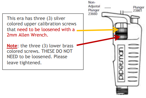
    Old-Style Pipetman: Introduced in July 1979. Serial numbers range from H-79xxxxx through N-85xxxxx. Two-piece piston assemblies introduced June 1982 (G-82xxxxx). Have three (3) upper silver colored calibration screws, and three (3) lower brass colored screws. The actual calibration mechanism is silver colored not upgraded to a black calibration screw as with the next Pipette era below.

    This Pipetman era has three (3) silver colored upper calibration screws that need to be loosened with a 2mm Allen Wrench.

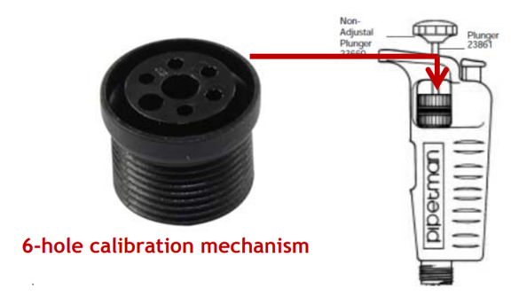
    All of the Gilson Pipetman eras have the same black colored, 6-hole calibration screw as shown below.

    New-Style Pipetman: Introduced in January 1986 featuring a sturdier and new serial 6-hole calibration mechanism numbers CxxxxxA through JxxxxxA.

    Modified Pipetman: Introduced in February 1991 featuring a new long-life friction ring. Serial numbers are JxxxxxB through NxxxxxE.

    Plunger-Adjustable Pipetman: Introduced in December 1995 featuring easier adjustment by using the volume adjustment knob or by turning the plunger button. Serial numbers range from NxxxxxE and higher.

    6 hole calibration mechanism

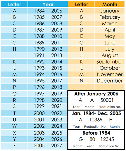
    See the chart below for Gilson Pipetman year classifications.

    Chart for Gilson Pipetman era/year classifications
    Related Posts:

    Styles of Gilson Pipette Tip Ejectors

    Trouble Shooting Gilson Pipetman Calibration Concerns

    Gilson Pipetman Counter Assembly Realignment

    Pipetman Calibration Wrench, Item # 27777

    Disclaimer: Any action you take using the information on this website is strictly at your own risk. The information herein does not constitute professional advice and is general in nature. We make no warranty that this information will meet your requirements, be safe, accurate, or error-free. Pipette Supplies, Inc. is not responsible for any errors or omissions, any results obtained from the use of this information, or any loss or damage arising out of the use of this information. This site is for educational purposes only.
    Fair Use: Copyright Disclaimer under section 107 of the Copyright Act of 1976, allows for “fair use” for purposes such as comments, criticism, teaching, scholarship, news reporting, and research.
    Fair use is permitted by copyright statute that might otherwise be infringing.
  • Troubleshooting Gilson Pipetman Calibration Concerns

    Pipetman Calibration Troubleshooting:

    Printable Calibration Log
    Printable Calibration Stickers (for use with Avery 5960 labels)

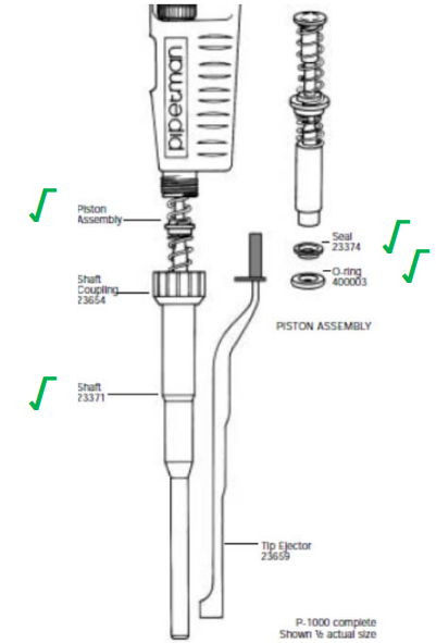
    Before any Pipetman calibration adjustments are made, the seal, o-ring, shaft, piston, and pipette tip performance needs to be confirmed as being good and fully functional. These five (5) components account for 95% of all pipette performance issues with accuracy and precision (percentages below). Calibration adjustments are always the last resort after determining that the following parts are in good condition and functioning well:

    • Seal and O-Ring 60%
    • Piston 20%
    • Shaft and Tips 10%
    • Pipette Handle/Body 5%
    Pipetman parts schematic
    Troubleshooting Pipetman calibration adjustments after confirming that the 5 Parts above are fully functioning:
    • For pipettes that have three (3) silver calibration screws on the upper side portion of the volume adjustment knob and that are within the serial number sequence of H-79xxxxx – N-85xxxxx: Loosen the two-piece piston assemblies (introduced June 1982 [G-82xxxxx]) with a 2mm Allen wrench. Do not loosen the three (3) bottom brass colored screws. The upper three silver screws must be loosened before calibration is permissible.
      • If the upper, silver screws will not loosen due to being stripped, try a 3mm Allen wrench or a special drill bit that removes stripped or damaged screws.
      • Use a cordless drill on slowest speed setting and replace the three silver calibration screws.
    • For pipettes that have a black, plastic, 6-hole calibration screw that won’t turn:
      • This could be due to:
        • The calibration screw is already adjusted to its maximum allowable range.
        • The coefficient of expansion and contraction of the plastic parts in changing environmental conditions and over time. Expansion and contraction of the plastic has a subtle impact in cold/hot seasons. 
        • Black calibration screw threads could be stripped or cross-threaded.
      • Gently clean and scrub the top of the calibration screw with IPA and a soft-bristled toothbrush. This is a difficult task, requires skill, and has a low success rate.
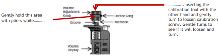
      • If the calibration screw won’t adjust after the 1st attempt, gently hold the black volume adjustment knob and friction ring with pliers (see tip below). Simultaneously, attempt to adjust the calibration with the calibration tool in the other hand. The extra leverage of the pliers holding the volume adjustment knob in place may provide the necessary torque when using the calibration tool to adjust.
    Pipetman volume adjustment knob. Gently hold this area with pliers while inserting the calibration tool with the other hand and gently turn to loosen calibration screw. Gentle turns to see if it will loosen.
    PROFESSIONAL TIP:

    Use rubber grips for the end of your pliers or wrench. The rubber helps to prevent damage to the friction ring and micro bolt. These can be purchased at any local hardware store or online.

    Pliers with rubber grips

    You can also buy plastic shrink tubing, cut it to the desired size, and heat/shrink it in place it over the plier nibs.  This is the cheaper option; however, the tubing only lasts 2-3 months before it needs to be cut off and replaced.

    Reminder: Adjusting the calibration should always be a last resort after the seal, o-ring, shaft, piston, and tips have been deemed fully functioning. 

    Overall, if the calibration screws cannot be adjusted, we recommend sending the pipettes to a calibration service provider. The pipette may require replacement of the calibration screw and/or the volume adjustment knob.

    Pipetman Calibration Tools/Instructions:

    Pipetman Calibration Wrench, Item # 27777
    Gilson Pipetman L Calibration Tool, Item # 28888

    Related Posts:

    Pipette Parts – Life Span, Life Cycle, and Performance
    Counter Assembly Instructions for Gilson Pipetman / Rainin Classic
    Styles of Gilson Pipette Tip Ejectors
    Differentiating Between Different Gilson Pipetman Eras
    Gilson Pipetman Teflon vs. Polyethylene Seals

    Disclaimer: Any action you take using the information on this website is strictly at your own risk. The information herein does not constitute professional advice and is general in nature. We make no warranty that this information will meet your requirements, be safe, accurate, or error-free. Pipette Supplies, Inc. is not responsible for any errors or omissions, any results obtained from the use of this information, or any loss or damage arising out of the use of this information. This site is for educational purposes only.
    Fair Use: Copyright Disclaimer under section 107 of the Copyright Act of 1976, allows for “fair use” for purposes such as comments, criticism, teaching, scholarship, news reporting, and research.
    Fair use is permitted by copyright statute that might otherwise be infringing.
  • Gilson Pipetman Teflon vs. Polyethylene Seals

    PipetteSupplies.com stocks both Teflon and Polyethylene piston seals. Polyethylene Pipetman seals are the most popular option and are injection molded. Teflon Pipetman seals are machine molded.  Polyethylene seals have tighter tolerances; Teflon seals are more pliable, and tighter. Both seals are autoclavable once and have about the same durability.

    Related Posts:

    Pipette Parts – Life Span, Life Cycle, and Performance

    Troubleshooting Gilson Pipetman Calibration Concerns

    Styles of Gilson Pipette Tip Ejectors

    Disclaimer: Any action you take using the information on this website is strictly at your own risk. The information herein does not constitute professional advice and is general in nature. We make no warranty that this information will meet your requirements, be safe, accurate, or error-free. Pipette Supplies, Inc. is not responsible for any errors or omissions, any results obtained from the use of this information, or any loss or damage arising out of the use of this information. This site is for educational purposes only.
    Fair Use: Copyright Disclaimer under section 107 of the Copyright Act of 1976, allows for “fair use” for purposes such as comments, criticism, teaching, scholarship, news reporting, and research.
    Fair use is permitted by copyright statute that might otherwise be infringing.