Author: Pipette Supplies Team

  • Pipette Parts – Life Span, Life Cycle, and Performance

    The life span of pipette parts may vary based on the:

    • Frequency of pipette use, and if used by multiple personnel
    • Types of liquids aspirated and dispensed
    • Storage conditions when not in use
    • Frequency of preventive maintenance and calibration service
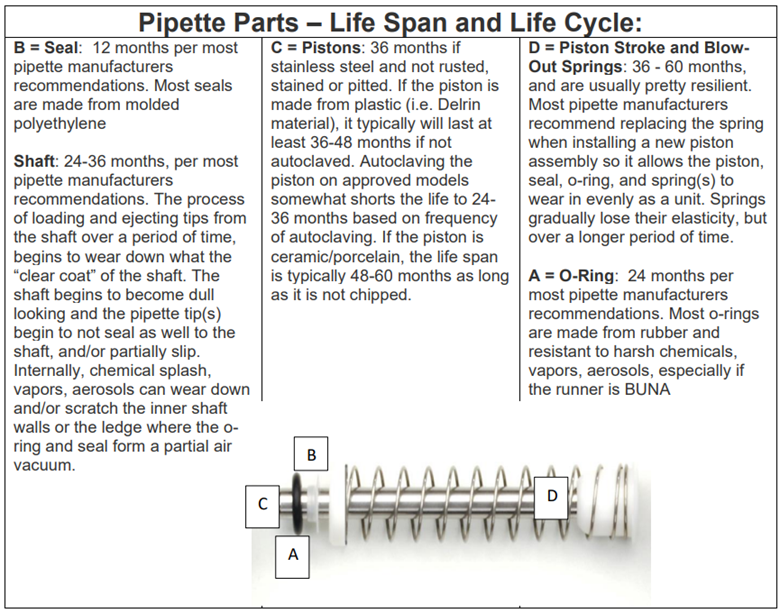
    pipette parts - life span and life cycle chart
    There are five (5) common pipette parts/components that attribute to ~95% of all performance issues. These five parts are:
    • Seal and O-Ring
      • Roughly 60% of all pipette performance concerns are the direct result of a seal and/or o-ring failure
    • Piston Assembly
      • Roughly 20% of all pipette performance concerns are the direct result of a rusted, pitted, chemical splash, bent/warped, or chipped piston
    • Shaft
      • Roughly 10% of all pipette performance concerns are the direct result of a worn, chemical splash shaft that prevents tips to seal optimally
    • Tip(s)
      • Tips can account for up to 5% of performance issues. This rate could be higher if tips are used from a manufacturer different than the pipette manufacturer.  Manufacturer’s design their pipettes to perform best with their tips. While other tip brands may be compatible, the end user should verify that the volume aspirated and dispensed is desirable. 
    • Handle/Body
      • The remaining 5% of performance concerns are typically caused by a part inside the pipette body (i.e.: bent plunger rod, calibration screw, volume display, etc.).

    Related Posts:

    Top 10 Crimes Committed Against Pipettes

    Frequency of Preventative Maintenance and Calibration

    General Troubleshooting – Liquid Leak Check Testing & 12 Point Pipette Inspection

    Disclaimer: Any action you take using the information on this website is strictly at your own risk. The information herein does not constitute professional advice and is general in nature. We make no warranty that this information will meet your requirements, be safe, accurate, or error-free. Pipette Supplies, Inc. is not responsible for any errors or omissions, any results obtained from the use of this information, or any loss or damage arising out of the use of this information. This site is for educational purposes only.
    Fair Use: Copyright Disclaimer under section 107 of the Copyright Act of 1976, allows for “fair use” for purposes such as comments, criticism, teaching, scholarship, news reporting, and research.
    Fair use is permitted by copyright statute that might otherwise be infringing.
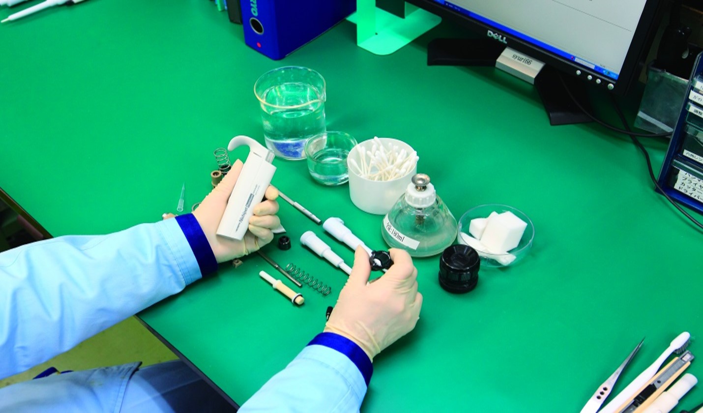
  • Frequency of Pipette Preventative Maintenance and Calibration

    Most major manufacturers recommend pipette preventative maintenance (PM) and calibration service at least every 12 months, based on use. Twelve months is a good starting interval and should include:

    • A liquid leak test, 12-point inspection
    • Cleaning
    • Manufacturer recommended pipette preventative maintenance
    • Replacement of common PM parts, such as the seal
    • lubrication of the piston assembly with manufacturer lubricant (as required by the manufacturer)
    • And calibration adjustments, as needed. Calibration should be a last resort after all other components are deemed good.

    Printable Calibration Log
    Printable Calibration Stickers (for use with Avery 5960 labels)

    pipette disassembly for preventative maintenance

    Disclaimer: Any action you take using the information on this website is strictly at your own risk. The information herein does not constitute professional advice and is general in nature. We make no warranty that this information will meet your requirements, be safe, accurate, or error-free. Pipette Supplies, Inc. is not responsible for any errors or omissions, any results obtained from the use of this information, or any loss or damage arising out of the use of this information. This site is for educational purposes only.
    Fair Use: Copyright Disclaimer under section 107 of the Copyright Act of 1976, allows for “fair use” for purposes such as comments, criticism, teaching, scholarship, news reporting, and research.
    Fair use is permitted by copyright statute that might otherwise be infringing.
  • The Reality of Electronic Pipette Calibration

    Electronic Pipette Calibration:

    Instead of the traditional pipetting button and manual volume adjustment, electronic pipettes feature a digital interface to adjust volume, and a motorized piston for aspiration/dispensing.  They use either a stepper motor (using a stepper linear actuator) or a DC motor with an encoder.

    Like mechanical pipettes, most electronic pipette calibration issues are due to leaks in the liquid end. This is often caused by wear in the sealing components.

    Unlike mechanical pipettes, electronic pipettes are “self-calibrating”.  If inaccuracy is due to a glitch in the electronic controller or the motor gets “out of step”, it can be corrected by doing a reset. The reset option is generally found in the ‘menu’, which is detailed in the user manual. 

    Therefore, electronic pipettes do not need to be calibrated in the ‘real sense’. They need to be verified for accuracy and precision on an appropriate 4-5 place or 6-7 place balance for micropipettes. If you find inaccuracy, test the pipette for a leak in the liquid end: aspirate full volume, take out and hold the pipette at eye level for about 15 seconds, and observe for a tiny droplet forming at the tip orifice. No droplet means no leak. If a leak is found, replace the sealing components (seal + o-ring or o-ring + grease) and your pipette should be in full calibration.

    Printable Calibration Log
    Printable Calibration Stickers (for use with Avery 5960 labels)

    electronic pipette s
    Related Posts:

    Pipette Parts – Life Span, Life Cycle, and Performance

    Top 10 Crimes Committed Against Pipettes

    Sartorius Picus: Handle Assembly/Disassembly

    Disclaimer: Any action you take using the information on this website is strictly at your own risk. The information herein does not constitute professional advice and is general in nature. We make no warranty that this information will meet your requirements, be safe, accurate, or error-free. Pipette Supplies, Inc. is not responsible for any errors or omissions, any results obtained from the use of this information, or any loss or damage arising out of the use of this information. This site is for educational purposes only.
    Fair Use: Copyright Disclaimer under section 107 of the Copyright Act of 1976, allows for “fair use” for purposes such as comments, criticism, teaching, scholarship, news reporting, and research.
    Fair use is permitted by copyright statute that might otherwise be infringing.

  • Manufacturer-Made Pipette Tips Vs. Others

    There are many different standard/universal pipette tips on the market that can be used and interchanged across different manufacturer’s pipettes. However, lower price and universal fit is not always the best logic when selecting tips for your pipettes.

    Manufacturer-Made Tip Used With That Manufacturer’s Pipette

    This pair provides the best results. The tips are specifically designed to load, seal, and deliver the desired volume of liquid accurately and precisely.

    Universal Tips Used With A Different Manufacturer’s Pipettes

    If mixing manufacturers, users can expect up to a 10% margin of error in the volume of liquid aspirated/dispensed. This is due to various factors, such as:

    • Tip sealing
    • Pore size of filtered tips
    • Tip thickness
    • Tip opening
    • Flash
    • Tip autoclaving

    Note: If filtered pipette tips are used, the pore size (micron size of the holes in the filter that allow air to pass/permeate through) can affect the volume of liquid dispensed due to different pore sizes and materials used by different tip manufacturers). Air flow can begin to be restricted when the pore size is smaller than ~20uM (microns).

    Different sizes and types of pipette tips

    Disclaimer: Any action you take using the information on this website is strictly at your own risk. The information herein does not constitute professional advice and is general in nature. We make no warranty that this information will meet your requirements, be safe, accurate, or error-free. Pipette Supplies, Inc. is not responsible for any errors or omissions, any results obtained from the use of this information, or any loss or damage arising out of the use of this information. This site is for educational purposes only.
    Fair Use: Copyright Disclaimer under section 107 of the Copyright Act of 1976, allows for “fair use” for purposes such as comments, criticism, teaching, scholarship, news reporting, and research.
    Fair use is permitted by copyright statute that might otherwise be infringing.
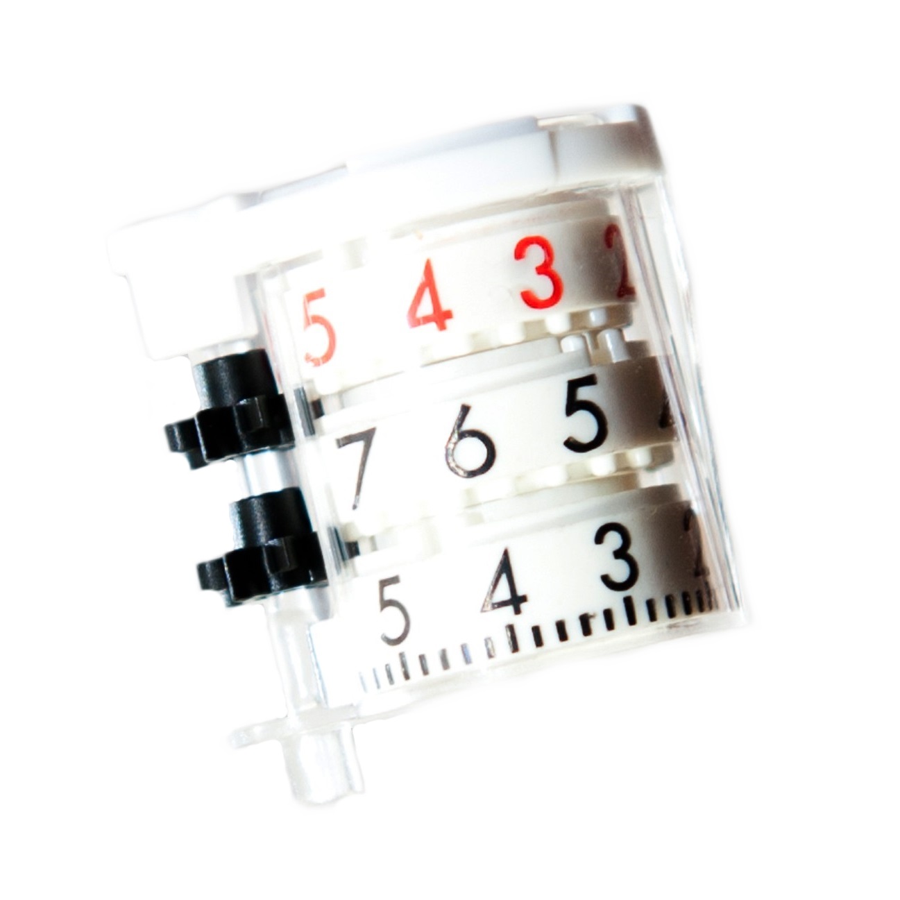
  • Gilson Pipetman Counter Assembly Realignment

    Ever needed to repair a Pipetman counter assembly?   

    For Pipetman G, Neo, and Classic:

    First, determine what necessitates the repair.  If one of the propelling gears has a broken tooth, the repair is not so simple. These repairs should only be attempted by a service provider.

    If the malfunction is due to the counter assembly being out of alignment because:

    • One or more of the rotating wheels has jumped off the track (from over winding)
    • The pipette had a trauma (possibly falling too many times on the floor)
    It can be easily repaired by following procedure:

    Unwind or start rotating the counter assembly towards its highest reading (1000ul towards 1000 etc.) either holding from the area where the friction ring is, or just rotating the plunger button (depending on the Pipetman model). When the knob with the friction ring reaches the upper end of the pipette body, it will require extra force to turn and may require pliers. Rotating past that point, you will need to add the “pulling out” motion to the rotating motion. At a certain point, the micro-bolt (the one with threaded circumference and a groove on its length) will freely come out.

    Look inside the cavity where the micro-bolt came out. There should be a white tab protruding from the inside diameter of the rotating rings that bear the numbers on them which you read in the counter window.  With a very thin screwdriver or extended forceps, turn the tab clockwise or counter clockwise to reach the following readings in the counter window (it may take many turns):

                Models P10, P100, P1000, P10ML = 130 – 133

                Models P2, P20, P200                      = 310 – 315

                Model P5000                                     = 630 – 675 

    Reinsert the micro-bolt assembly into the Pipetman body without rotation of the volume display.  Note: The tab inside the body must align with the groove on the micro-bolt.

    Finally, gravimetrically test the pipette on a balance to verify accuracy and precision.

    For Pipetman L:

    Thanks to the comment below, we would like to clarify that the instructions for the Pipetman L contain only one difference: you need to remove the lock/unlock assembly before you can access the counter assembly. Use the Pipetman L Cap spanner tool to do this, GI FA07052.

    PIpetman counter assembly

    Disclaimer: Any action you take using the information on this website is strictly at your own risk. The information herein does not constitute professional advice and is general in nature. We make no warranty that this information will meet your requirements, be safe, accurate, or error-free. Pipette Supplies, Inc. is not responsible for any errors or omissions, any results obtained from the use of this information, or any loss or damage arising out of the use of this information. This site is for educational purposes only.
    Fair Use: Copyright Disclaimer under section 107 of the Copyright Act of 1976, allows for “fair use” for purposes such as comments, criticism, teaching, scholarship, news reporting, and research.
    Fair use is permitted by copyright statute that might otherwise be infringing.
  • General Troubleshooting – Liquid Leak Test Testing & 12 Point Pipette Inspection

    Liquid Leak Test

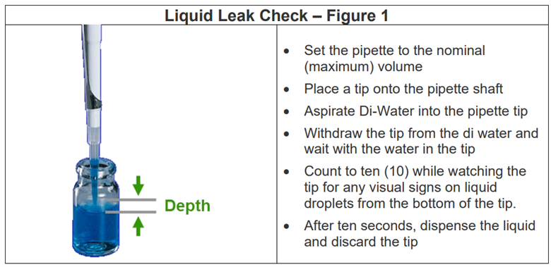
    A simple liquid leak test will help determine if a pipette sealing system (i.e. piston, seal, shaft, o-ring, and tip) is working as it should, and may uncover hidden problems not seen to the naked eye.

    Liquid Leak test instructions
    12 Point Pipette Inspection

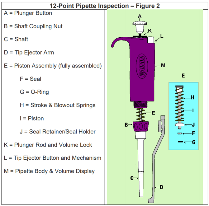
    The information provided in the table below will help identify pipette parts and components that could require replacement or be causing underlying concerns that may not be seen to the naked eye. Routine pipette inspection checks (at least monthly) will aid in keeping your pipettes performing optimally.

    Note: The picture below is a RAININ Pipet-Lite. For most parts, it will provide visual clarity and guide for different manufacturer pipette models in the market. Inspection of the seal, o-ring, piston assembly, and shaft may require that the pipette calibration be re-verified after a minimum equilibration period of 1- hour has passed. The equilibration period is needed to allow the pipette to conform, contract, and adapt back to ambient laboratory temperature.

    12 point pipette instruction schematic

    Disclaimer: Any action you take using the information on this website is strictly at your own risk. The information herein does not constitute professional advice and is general in nature. We make no warranty that this information will meet your requirements, be safe, accurate, or error-free. Pipette Supplies, Inc. is not responsible for any errors or omissions, any results obtained from the use of this information, or any loss or damage arising out of the use of this information. This site is for educational purposes only.
    Fair Use: Copyright Disclaimer under section 107 of the Copyright Act of 1976, allows for “fair use” for purposes such as comments, criticism, teaching, scholarship, news reporting, and research.
    Fair use is permitted by copyright statute that might otherwise be infringing.
  • Eppendorf Repeater M4 “CO2 ERR” Message

    If you are receiving a “CO2 ERR” message on your Eppendorf Repeater M4, the potential root cause could be:

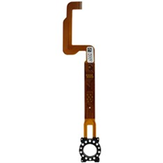
    Combitip Sensor M4, part number: EP 4982811002, has become defective.

    Either the white, round sensor(s) are not recognizing the combitip advanced syringes, or the bronze-colored internal sensor strip is damaged. Replacement sensors can be found here.

    Repeater Mr internal sensor strip. If defective, it could cause the M4 C02 ERR.
    You may have mixed batches of Eppendorf Combitip-Plus and Combitip-Avanced syringes. 

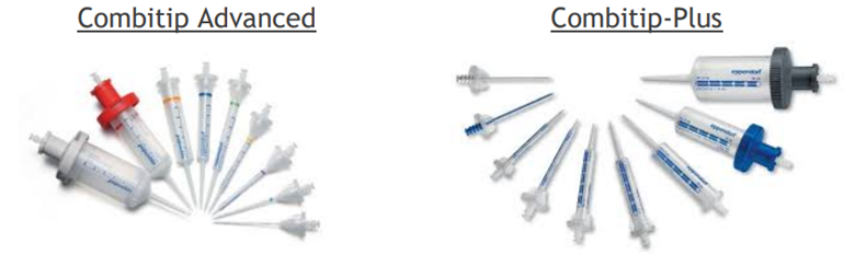
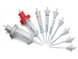
    The M4 repeater is designed to be used with the Combitip-Advanced syringes. If an older style syringe, like the Combitip-Plus, is inserted onto the unit, the Combitip M4 sensor will not recognize it, thus triggering an CO2 ERR/CO3 ERR. The pictures below show the difference.

    Eppendorf Combitip-Advanced: 

    Eppendorf Combitip-Advanced

    Eppendorf Combitip-Plus (most look like this, with some minor differences in appearance):

    Eppendorf Combitip-Plus

    The syringe ejector tabs are misaligned, thus preventing the syringe from being loaded and aligned properly with the combitip sensor.

    The ejector tabs are charcoal colored/black and “C” shaped on the left and right side of the combitip sensor.  It would be relatively easy to notice if the syringe is not loaded fully vertically and looks slanted or misaligned when loaded.

    Of course, without seeing the unit, it is more difficult to 100% diagnose the exact cause of the Repeater M4 CO2 ERR.  If the unit is confirmed under warranty, consider reaching out to Eppendorf for assistance.  

    Disclaimer: Any action you take using the information on this website is strictly at your own risk. The information herein does not constitute professional advice and is general in nature. We make no warranty that this information will meet your requirements, be safe, accurate, or error-free. Pipette Supplies, Inc. is not responsible for any errors or omissions, any results obtained from the use of this information, or any loss or damage arising out of the use of this information. This site is for educational purposes only.
    Fair Use: Copyright Disclaimer under section 107 of the Copyright Act of 1976, allows for “fair use” for purposes such as comments, criticism, teaching, scholarship, news reporting, and research.
    Fair use is permitted by copyright statute that might otherwise be infringing.
  • Eppendorf Repeater Plus C-4 Error

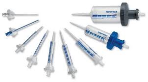
    If your Repeater Plus is showing a C-4 Error, you may be using incompatible tips with the sensor in your pipette. The two types of Combitips are shown below, Combitip Advanced and Combitip-Plus.

    Combitip Advanced vs Combitip Plus

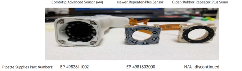
    The older, rubber style sensor (see far right below), it not fully compatible with Eppendorf’s Advanced Combitip Syringes, especially if the rubber portion of the sensor is worn. This could be the cause of the Repeater Plus C-4 Error.

    Combitip Advanced Sensor, Newer Repeater-Plus Sensor, Older/Rubber Repeater Plus Sensor
    Recommendations:

    To enable your pipette to use Combitip Advanced syringes, there are multiple recommendations to consider based on cost and time.

    Option 1: Order part number EP 4981802000 and install yourself. NOTE: There is always the possibility of other hidden internal damage. The pipette may need to be sent to an accredited service provider. It is harder to properly diagnosis hidden damage without seeing it first-hand.

    • Option 2: Eppendorf NA Service can likely install the Combitip sensors and calibrate it for you. Eppendorf Service: https://serviceportal.eppendorf.com/en-US/login or call 800-645-3050.

    Option 3: Upgrade or trade-in your units for the Eppendorf Repeater M4

    Disclaimer: Any action you take using the information on this website is strictly at your own risk. The information herein does not constitute professional advice and is general in nature. We make no warranty that this information will meet your requirements, be safe, accurate, or error-free. Pipette Supplies, Inc. is not responsible for any errors or omissions, any results obtained from the use of this information, or any loss or damage arising out of the use of this information. This site is for educational purposes only.
    Fair Use: Copyright Disclaimer under section 107 of the Copyright Act of 1976, allows for “fair use” for purposes such as comments, criticism, teaching, scholarship, news reporting, and research.
    Fair use is permitted by copyright statute that might otherwise be infringing.
  • Differentiating Between Different Gilson Pipetman Eras

    Gilson Pipetman Eras:

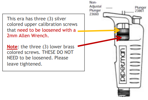
    Old-Style Pipetman: Introduced in July 1979. Serial numbers range from H-79xxxxx through N-85xxxxx. Two-piece piston assemblies introduced June 1982 (G-82xxxxx). Have three (3) upper silver colored calibration screws, and three (3) lower brass colored screws. The actual calibration mechanism is silver colored not upgraded to a black calibration screw as with the next Pipette era below.

    This Pipetman era has three (3) silver colored upper calibration screws that need to be loosened with a 2mm Allen Wrench.

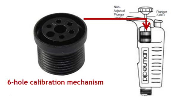
    All of the Gilson Pipetman eras have the same black colored, 6-hole calibration screw as shown below.

    New-Style Pipetman: Introduced in January 1986 featuring a sturdier and new serial 6-hole calibration mechanism numbers CxxxxxA through JxxxxxA.

    Modified Pipetman: Introduced in February 1991 featuring a new long-life friction ring. Serial numbers are JxxxxxB through NxxxxxE.

    Plunger-Adjustable Pipetman: Introduced in December 1995 featuring easier adjustment by using the volume adjustment knob or by turning the plunger button. Serial numbers range from NxxxxxE and higher.

    6 hole calibration mechanism

    See the chart below for Gilson Pipetman year classifications.

    Chart for Gilson Pipetman era/year classifications
    Related Posts:

    Styles of Gilson Pipette Tip Ejectors

    Trouble Shooting Gilson Pipetman Calibration Concerns

    Gilson Pipetman Counter Assembly Realignment

    Pipetman Calibration Wrench, Item # 27777

    Disclaimer: Any action you take using the information on this website is strictly at your own risk. The information herein does not constitute professional advice and is general in nature. We make no warranty that this information will meet your requirements, be safe, accurate, or error-free. Pipette Supplies, Inc. is not responsible for any errors or omissions, any results obtained from the use of this information, or any loss or damage arising out of the use of this information. This site is for educational purposes only.
    Fair Use: Copyright Disclaimer under section 107 of the Copyright Act of 1976, allows for “fair use” for purposes such as comments, criticism, teaching, scholarship, news reporting, and research.
    Fair use is permitted by copyright statute that might otherwise be infringing.
  • Troubleshooting Gilson Pipetman Calibration Concerns

    Pipetman Calibration Troubleshooting:

    Printable Calibration Log
    Printable Calibration Stickers (for use with Avery 5960 labels)

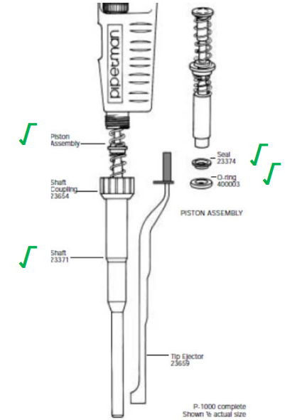
    Before any Pipetman calibration adjustments are made, the seal, o-ring, shaft, piston, and pipette tip performance needs to be confirmed as being good and fully functional. These five (5) components account for 95% of all pipette performance issues with accuracy and precision (percentages below). Calibration adjustments are always the last resort after determining that the following parts are in good condition and functioning well:

    • Seal and O-Ring 60%
    • Piston 20%
    • Shaft and Tips 10%
    • Pipette Handle/Body 5%
    Pipetman parts schematic
    Troubleshooting Pipetman calibration adjustments after confirming that the 5 Parts above are fully functioning:
    • For pipettes that have three (3) silver calibration screws on the upper side portion of the volume adjustment knob and that are within the serial number sequence of H-79xxxxx – N-85xxxxx: Loosen the two-piece piston assemblies (introduced June 1982 [G-82xxxxx]) with a 2mm Allen wrench. Do not loosen the three (3) bottom brass colored screws. The upper three silver screws must be loosened before calibration is permissible.
      • If the upper, silver screws will not loosen due to being stripped, try a 3mm Allen wrench or a special drill bit that removes stripped or damaged screws.
      • Use a cordless drill on slowest speed setting and replace the three silver calibration screws.
    • For pipettes that have a black, plastic, 6-hole calibration screw that won’t turn:
      • This could be due to:
        • The calibration screw is already adjusted to its maximum allowable range.
        • The coefficient of expansion and contraction of the plastic parts in changing environmental conditions and over time. Expansion and contraction of the plastic has a subtle impact in cold/hot seasons. 
        • Black calibration screw threads could be stripped or cross-threaded.
      • Gently clean and scrub the top of the calibration screw with IPA and a soft-bristled toothbrush. This is a difficult task, requires skill, and has a low success rate.
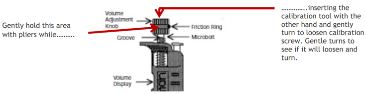
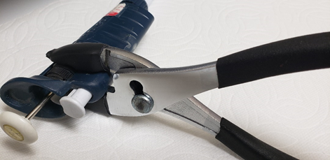
      • If the calibration screw won’t adjust after the 1st attempt, gently hold the black volume adjustment knob and friction ring with pliers (see tip below). Simultaneously, attempt to adjust the calibration with the calibration tool in the other hand. The extra leverage of the pliers holding the volume adjustment knob in place may provide the necessary torque when using the calibration tool to adjust.
    Pipetman volume adjustment knob. Gently hold this area with pliers while inserting the calibration tool with the other hand and gently turn to loosen calibration screw. Gentle turns to see if it will loosen.
    PROFESSIONAL TIP:

    Use rubber grips for the end of your pliers or wrench. The rubber helps to prevent damage to the friction ring and micro bolt. These can be purchased at any local hardware store or online.

    Pliers with rubber grips

    You can also buy plastic shrink tubing, cut it to the desired size, and heat/shrink it in place it over the plier nibs.  This is the cheaper option; however, the tubing only lasts 2-3 months before it needs to be cut off and replaced.

    Reminder: Adjusting the calibration should always be a last resort after the seal, o-ring, shaft, piston, and tips have been deemed fully functioning. 

    Overall, if the calibration screws cannot be adjusted, we recommend sending the pipettes to a calibration service provider. The pipette may require replacement of the calibration screw and/or the volume adjustment knob.

    Pipetman Calibration Tools/Instructions:

    Pipetman Calibration Wrench, Item # 27777
    Gilson Pipetman L Calibration Tool, Item # 28888

    Related Posts:

    Pipette Parts – Life Span, Life Cycle, and Performance
    Counter Assembly Instructions for Gilson Pipetman / Rainin Classic
    Styles of Gilson Pipette Tip Ejectors
    Differentiating Between Different Gilson Pipetman Eras
    Gilson Pipetman Teflon vs. Polyethylene Seals

    Disclaimer: Any action you take using the information on this website is strictly at your own risk. The information herein does not constitute professional advice and is general in nature. We make no warranty that this information will meet your requirements, be safe, accurate, or error-free. Pipette Supplies, Inc. is not responsible for any errors or omissions, any results obtained from the use of this information, or any loss or damage arising out of the use of this information. This site is for educational purposes only.
    Fair Use: Copyright Disclaimer under section 107 of the Copyright Act of 1976, allows for “fair use” for purposes such as comments, criticism, teaching, scholarship, news reporting, and research.
    Fair use is permitted by copyright statute that might otherwise be infringing.