In this case, you may need to send the device a service technician for repair. The issue could be mechanical, possibly with the motor or lower assembly.
Disclaimer: Any action you take using the information on this website is strictly at your own risk. The information herein does not constitute professional advice and is general in nature. We make no warranty that this information will meet your requirements, be safe, accurate, or error-free. Pipette Supplies, Inc. is not responsible for any errors or omissions, any results obtained from the use of this information, or any loss or damage arising out of the use of this information. This site is for educational purposes only. Fair Use: Copyright Disclaimer under section 107 of the Copyright Act of 1976, allows for “fair use” for purposes such as comments, criticism, teaching, scholarship, news reporting, and research. Fair use is permitted by copyright statute that might otherwise be infringing.
The process of removing, replacing, and reinstalling the piston assembly for the Biohit/Sartorius mLINE, eLINE, Proline Plus, Tacta, Picus, and Picus NxT single channel pipettes requires great care, a high attention to detail, patience, and steady hands. Please dedicate a good work area with good lighting and space where small parts can be located should they pop/fly out during disassembly. Pipette damage and lost parts may occur if attention to detail is not maintained. Please proceed at your own risk.
Preliminary Note: This disassembly process applies to the single-channel variants of each listed model. It is also recommended to inspect and replace the seal and any damaged components of the lower assembly during this procedure.
Step 1:
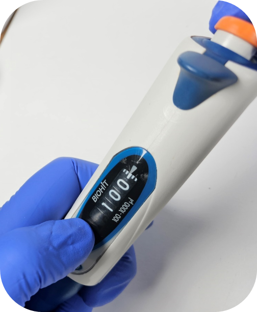
Adjust the pipette to its lowest volume setting. This allows for easier removal and installation of the piston.
Step 2:
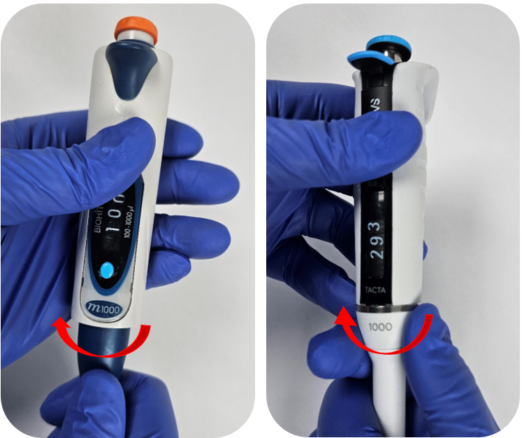
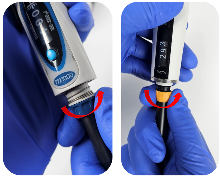
Unscrew the tip ejector sleeve in a counter-clockwise direction from the lower half of the pipette body.
Note: When removing the tip ejector for the Tacta, make sure to unscrew the ejector on the beveled edge below the silver ring on the body of the pipette.
Step 3:
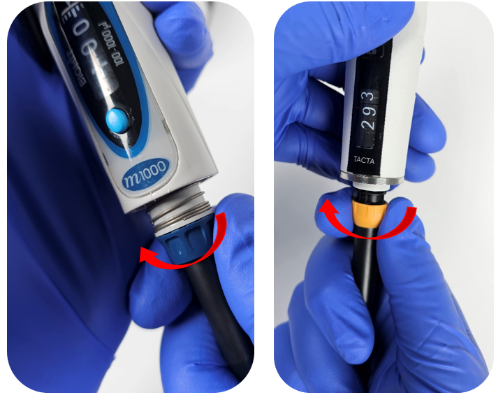
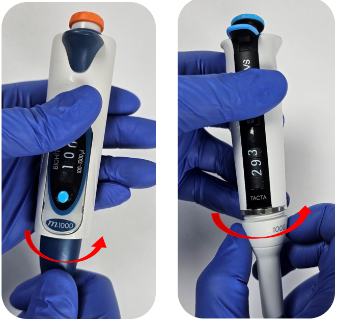
Unscrew the connecting nut counter-clockwise from the tip cone. Once disengaged, gently pull down on the tip cone to remove it from the pipette.
Step 4:
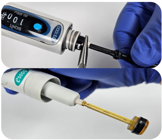
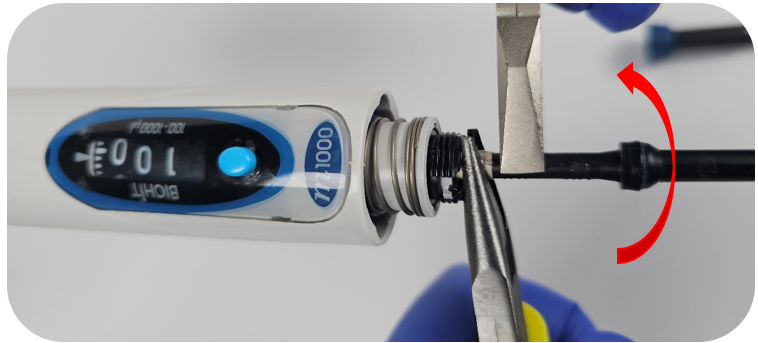
To remove the piston, use a pair of coated needle-nose pliers to grip the operating rod.
Note: Use pliers with a rubber or plastic coating to prevent damage to the plastic operating rod. If coated pliers are unavailable, wrap two layers of a nitrile glove around the operating rod to minimize the risk of damage while using pliers.
Step 5:
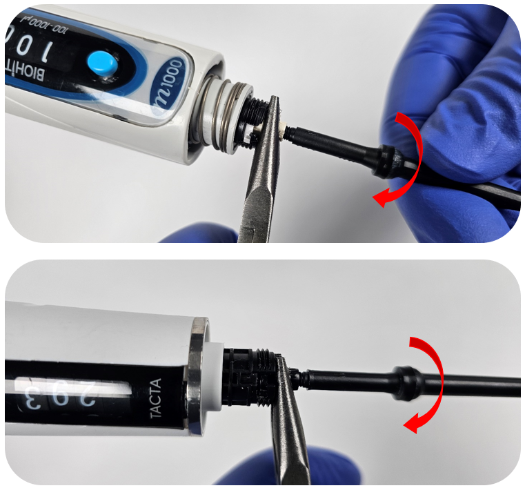
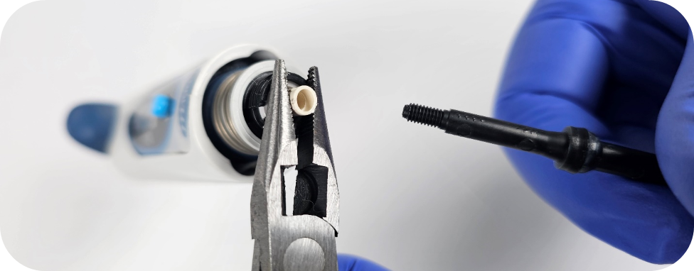
While holding the operating rod with the pliers, rotate the piston counter-clockwise to loosen it. The piston is usually hand-tightened, but you may need an extra set of coated pliers to remove it.
Step 6:
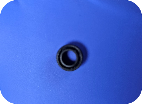
Inspect the seal before reassembly. If it appears cracked, deformed, or worn, it should be replaced.
Step 7:
Install the new Sartorius piston by threading the threaded end into the operating rod clockwise.
After tightening by hand, an additional pair of coated needle-nose pliers can be used to snug up the piston if needed.
Caution: Do not overtighten. Overtightening may cause damage to the threaded operating rod.
Step 8:
After confirming the seal is in good condition, reattach the tip holder and secure it with the connecting nut.
Step 9:
Reattach the ejector sleeve by threading it back onto the ejector assembly.
Step 10:
After replacement of the piston, it is a good idea to check the pipette to ensure it is operating within manufacturers specifications.
Disclaimer: Any action you take using the information on this website is strictly at your own risk. The information herein does not constitute professional advice and is general in nature. We make no warranty that this information will meet your requirements, be safe, accurate, or error-free. Pipette Supplies, Inc. is not responsible for any errors or omissions, any results obtained from the use of this information, or any loss or damage arising out of the use of this information. This site is for educational purposes only. Fair Use: Copyright Disclaimer under section 107 of the Copyright Act of 1976, allows for “fair use” for purposes such as comments, criticism, teaching, scholarship, news reporting, and research. Fair use is permitted by copyright statute that might otherwise be infringing.
Unscrew and remove the tip cone locking cover. Remove the tip cone.
Turn piston counterclockwise and remove.
Remove the operation button by pulling up.
Turn the adjustment wheel counterclockwise to reveal the small Phillips-type screw.
Remove the screw and ID Window.
Pull out the upper part of the top cover. Use your thumb to push, if necessary. Remove the top cover.
Use your thumbs to spread the back cover.
Remove the machinery.
Remove the battery and pull the connector out.
Assembly
Install the battery
Before installing the lower part, install the upper part of the machinery inside the battery cover.
Double check that the machinery was installed correctly.
Install the upper part of the top cover.
Use your thumb to push the cover down firmly. Press the lower part of the top cover to install it.
Re-screw the small Phillips-type screw under the adjustment wheel.
Install operation button. Bevel on the button should be on the same side as the finger grip, then notches will go into the groves.
Disclaimer: Any action you take using the information on this website is strictly at your own risk. The information herein does not constitute professional advice and is general in nature. We make no warranty that this information will meet your requirements, be safe, accurate, or error-free. Pipette Supplies, Inc. is not responsible for any errors or omissions, any results obtained from the use of this information, or any loss or damage arising out of the use of this information. This site is for educational purposes only. Fair Use: Copyright Disclaimer under section 107 of the Copyright Act of 1976, allows for “fair use” for purposes such as comments, criticism, teaching, scholarship, news reporting, and research. Fair use is permitted by copyright statute that might otherwise be infringing.
ATTENTION: Performing a calibration adjustment on any pipette should always be the last option, never the first. Performing a calibration adjustment first may mask underlying pipette performance issues that could affect both the short- and long-term health of your pipette. This could lead to costly repairs and part(s) replacement, and possibly the need to replace the pipette itself. Adjusting the pipette calibration should only occur after the pipette sealing system, (i.e.: piston, shaft, o-ring, lubricant, pipette tips) and other critical components are inspected to ensure good working condition. If not replace part(s) as needed first. If you are unsure if the parts are in good condition or which parts should be replaced, please contact Pipettesupplies.com.
Recommended mLine Pipette Calibration Adjustment Tools and Needed Equipment:
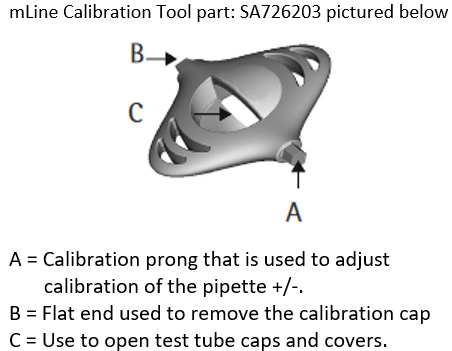
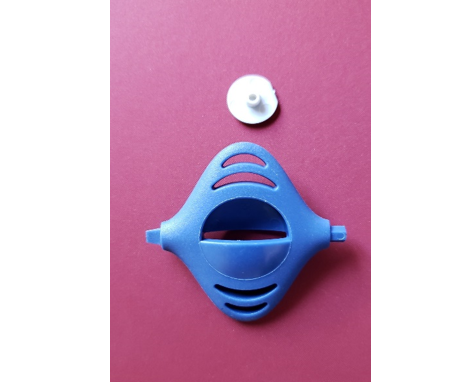
mLine Calibration Tool (Pipette Supplies Part Number SA 726203)
Pipette Tips (for checking the volume delivered after calibration adjustment is made)
Di Water non-aerated (for verifying the accuracy/precision after a calibration adjustment)
4-5 Place Balance (to gravimetrically confirm the desired volume aspirated and delivered is accurate and precise.)
Calibration Adjustment Process:
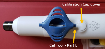
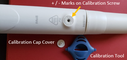
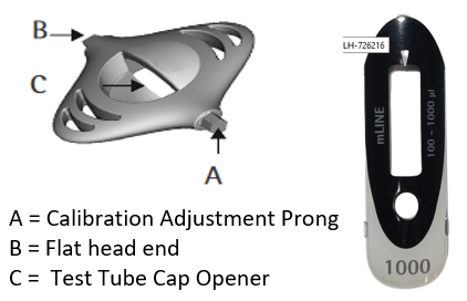
Step 1: Insert part B of the calibration tool into the calibration cap cover (SA 726006) that is located on the backside of the pipette body and gently pry off and remove the calibration cap. Lay aside in a safe location for re-installation later on. The calibration screw is now visible.
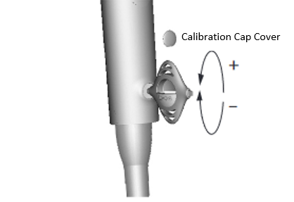
Step 2:(NOTE) Notice that the calibration screw will have a + and – symbol etched on it to indicate which direction the calibration adjustment tool should be turned to either increase (+) or decrease (-) the desired volume aspirated and dispensed by the pipette.
Step 3:(NOTE) If the current actual volume is lower or higher than desired then insert calibration tool:
Lower than desired: Slowly rotate the calibration adjustment tool no more than 1/8 of a turn in the counter–clockwise direction. This will increase the volume of liquid aspirated.
Higher than desired: Slowly rotate the calibration adjustment tool no more than 1/8 of a turn in the clockwise direction. This will decrease the volume of liquid aspirated.
Important: It is strongly recommended that any calibration adjustments occur at the 10% volume. This helps to ensure accuracy and precision is maintained throughout the pipette volume range (i.e., 20uL-200uL, 100uL -1000uL, etc.). Failure to do this could skew or affect the volume aspirated and dispensed at different tested volume points.
After Calibration Adjustment Process:
Remove the calibration adjustment tool from the pipette calibration screw
Install a pipette tip onto the pipette shaft
Pre-rinse the tip 2-3 times with Di-water
Aspirate and dispense the di water into a reservoir on a 4-5 place balance to confirm the new volume that is now being delivered
Repeat the calibration adjustment process if the new volume delivered is still too low or too high
(NOTE) If the pipette is not delivering the desired volume after performing calibration adjustments for 2-3 minutes, lay the pipette aside and allow it to equilibrate back to ambient lab conditions for 60 minutes. After this time period lapses, re-check the pipette calibration (i.e., due to possible hand warming effects).
Step 4: After the desired volume is verified on a 4-5 place balance, re-install the calibration cap. The mLINE pipette is now ready for use.
Disclaimer: Any action you take using the information on this website is strictly at your own risk. The information herein does not constitute professional advice and is general in nature. We make no warranty that this information will meet your requirements, be safe, accurate, or error-free. Pipette Supplies, Inc. is not responsible for any errors or omissions, any results obtained from the use of this information, or any loss or damage arising out of the use of this information. This site is for educational purposes only. Fair Use: Copyright Disclaimer under section 107 of the Copyright Act of 1976, allows for “fair use” for purposes such as comments, criticism, teaching, scholarship, news reporting, and research. Fair use is permitted by copyright statute that might otherwise be infringing.
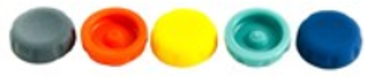
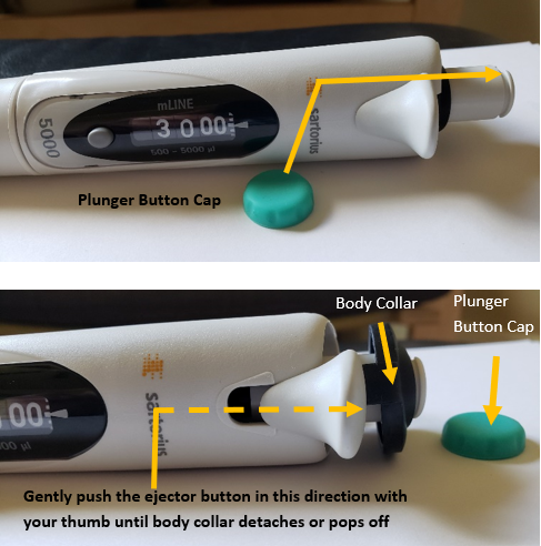
Gently pry and lift off the colored plunger button cap from the mLINE pipette and lay aside for reassembly later on. Shop all colors here.
Step 2:
Gently push up on the tip ejector button with your thumb to loosen/detach the black or blue colored body collar from the pipette. Lift and lay aside for reassembly later.
Step 3:
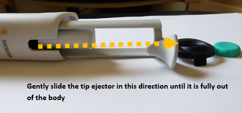
Continue to gently slide and remove the tip ejector mechanism from the pipette body until it is fully removed.
Step 3A:
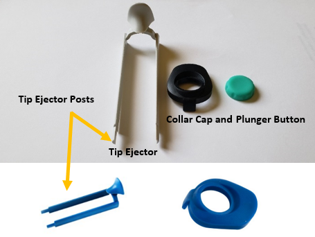
With the tip ejector removed, you should have these three parts laid aside:
New mLINE replacement Tip Ejector (gray or blue colored): SA 726005
Note: The tip ejector collars and tip ejector may come in a blue or gray color. Other than color, they are both the same and interchangeable
Step 4 Reassembly:
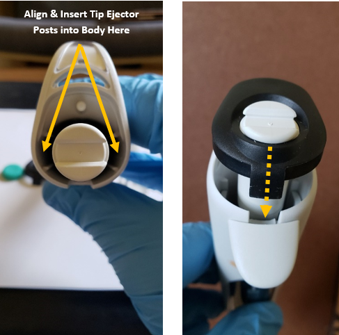
Gently line up the tip ejector posts with the body slots. Once aligned, slowly insert and slide the new tip ejector assembly fully into place.
Step 5 Reassembly:
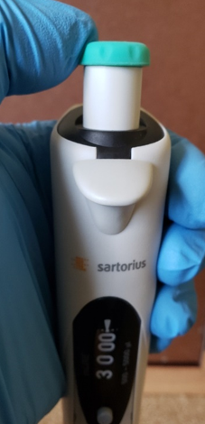
Re-attach the blue or black colored collar assembly. Gently push it down until it seats firmly in place.
Step 6 Reassembly:
Re-install the plunger button onto the pipette plunger rod.
Step 7 Reassembly:
Test out the newly replaced mLINE tip ejector by installing and ejecting pipette tips.
Disclaimer: Any action you take using the information on this website is strictly at your own risk. The information herein does not constitute professional advice and is general in nature. We make no warranty that this information will meet your requirements, be safe, accurate, or error-free. Pipette Supplies, Inc. is not responsible for any errors or omissions, any results obtained from the use of this information, or any loss or damage arising out of the use of this information. This site is for educational purposes only. Fair Use: Copyright Disclaimer under section 107 of the Copyright Act of 1976, allows for “fair use” for purposes such as comments, criticism, teaching, scholarship, news reporting, and research. Fair use is permitted by copyright statute that might otherwise be infringing.
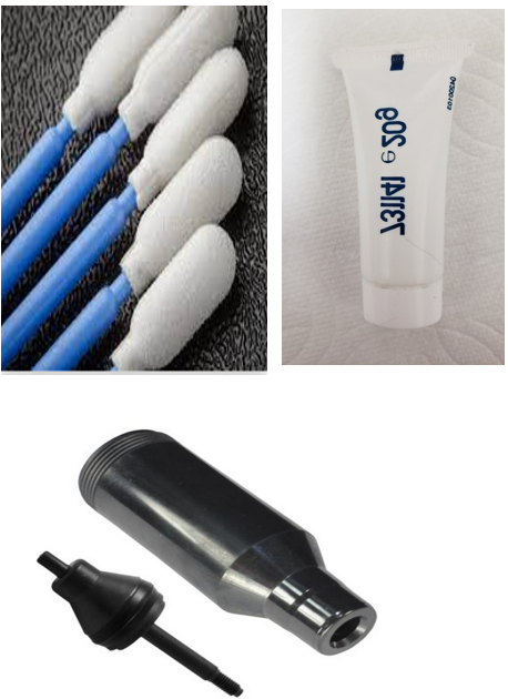
Note: As Preventive Maintenance (PM) is performed, there may be a need to replace one or more of the following parts based on pipette part condition and wear and tear.
mLINE Piston
O-ring
Shaft
Lubricant
Shaft, O-Ring, & Piston Assembly (SA 726097). Only sold as a kitted item not individually as shown.
Step 1:
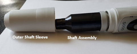
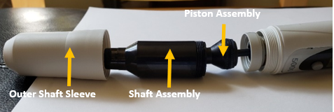
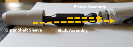
Loosen the outer shaft sleeve by carefully unscrewing it. Once unscrewed, remove and lay aside for reassembly later.
Step 2:
Loosen the black colored shaft assembly from the body by carefully unscrewing it. Once fully unscrewed, lay aside for preventive maintenance
Note: When the black shaft assembly is removed, you may see visible lubricant on the piston as well as inside the large orifice open of the shaft. This is okay and will be cleaned during PM.
Step 3:
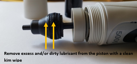
With the piston now exposed, use a clean kim wipe to gently wipe and remove any lubricant, chemical splash, or debris from the piston as well as inside the large portion of the shaft opening.
Note: Repeated wiping with the same kim wipe is not recommended. Please wipe only once and disregard to avoid scratching the piston, piston o-ring, and inside of the shaft.
Step 4:
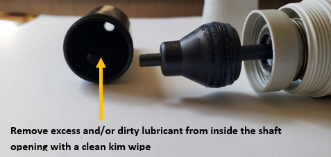
With the shaft now exposed, use a clean kim wipe to gently wipe and remove any lubricant from the piston as well as inside the large portion of the shaft opening.
Note: Be sure the piston and shaft do not have any visible amounts of lubricant after cleaning.
Step 5:
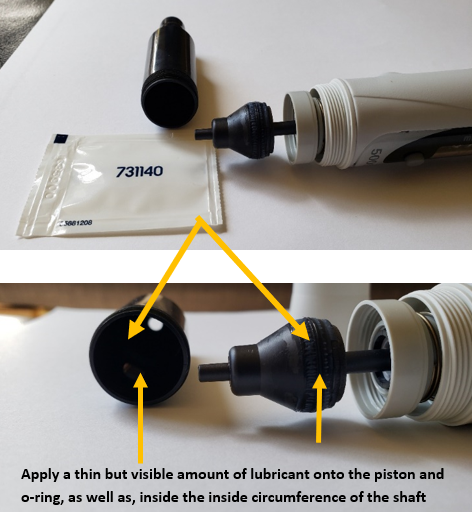
With a clean foam swap, apply a thin amount of the Sartorius pn: SA LH-731141 onto to it. Gently coat the piston o-ring with a thin layer of lubricant around the entire circumference of the piston o-ring.
DO NOT over apply with a thick coat of lubricant. Just enough for it to be seen visibly on the piston o-ring.
Step 6 Reassembly:
Reattach and carefully screw the black shaft onto the mLINE piston assy.
Step 7 Reassembly:
Reattach the outer shaft sleeve to the piston by carefully screwing it onto the body.
Helpful Tip: Once the pipette is fully reassembled, set the pipette volume to 5000uL and place a 5000uL tip onto the shaft.
Fully aspirate 5000uL Di water into the tip
Slowly withdrawal the tip from the di water reservoir
With the water still in the tip, count to 10. The purpose is to see if any visible leaks will occur before proceeding to the next step.
If a leak is detected, please disassemble, remove lubricant, and reapply. If leak still occurs then it may be possible that the piston, o-ring, and or shaft may need to be replaced.
Step 8:
After a successful liquid leak test, allow the pipette to equilibrate for at least 60 minutes to ambient conditions after preventive maintenance (PM) is complete.
Step 9:
Once the equilibration period has ended, verify pipette accuracy and precision on a 4-5 place balance. If pipette meets acceptable accuracy and precision requirements then use freely. If it does not, please contact us at Pipettesupplies.com for additional support.
Disclaimer: Any action you take using the information on this website is strictly at your own risk. The information herein does not constitute professional advice and is general in nature. We make no warranty that this information will meet your requirements, be safe, accurate, or error-free. Pipette Supplies, Inc. is not responsible for any errors or omissions, any results obtained from the use of this information, or any loss or damage arising out of the use of this information. This site is for educational purposes only. Fair Use: Copyright Disclaimer under section 107 of the Copyright Act of 1976, allows for “fair use” for purposes such as comments, criticism, teaching, scholarship, news reporting, and research. Fair use is permitted by copyright statute that might otherwise be infringing.
Volume Lock Button (Counter Release Nut) – SA LH-726221
Note: Only replace the mLINE volume display window if it is cracked or if the tabs that hold it in place have broken off.
Step 1:
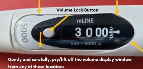
With Part B of the Sartorius calibration tool or a small bladed flat head screwdriver, gently pry/lift up a corner of the volume display window and remove.
Note: Be careful as the volume lock button may fall off from the window display during removal. Lay side for reassembly later on.
Step 2:
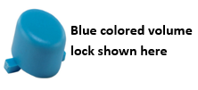
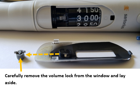
If the volume lock button did not come off during removal of the volume window, carefully remove and lay aside as shown.
The volume lock button may be gray or blue colored. Other than color, they are interchangeable.
Step 3 Reassembly:
Ensure that the three volume display window tabs are not cracked or broken.
Step 3A:
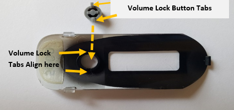
Align the volume lock button tabs with the volume display window and insert into place.
Step 4:
Once the volume lock cap is inserted into the volume display window:
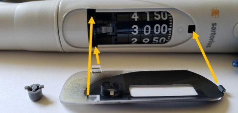
Align the volume display three (3) window tabs with the pipette body.
Carefully seat/secure the volume display window in place. Be extra careful to not damage or break the volume display window tabs during installation. Alignment is critical to avoid breakage.
Step 5:
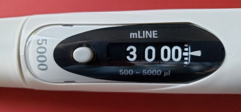
Once reassembled, test the volume adjustment by pressing the volume lock button and slowly adjusting the pipette volume. If the volume does not turn smoothly, recheck your work. Confirm that the volume lock button is properly seated.
Disclaimer: Any action you take using the information on this website is strictly at your own risk. The information herein does not constitute professional advice and is general in nature. We make no warranty that this information will meet your requirements, be safe, accurate, or error-free. Pipette Supplies, Inc. is not responsible for any errors or omissions, any results obtained from the use of this information, or any loss or damage arising out of the use of this information. This site is for educational purposes only. Fair Use: Copyright Disclaimer under section 107 of the Copyright Act of 1976, allows for “fair use” for purposes such as comments, criticism, teaching, scholarship, news reporting, and research. Fair use is permitted by copyright statute that might otherwise be infringing.