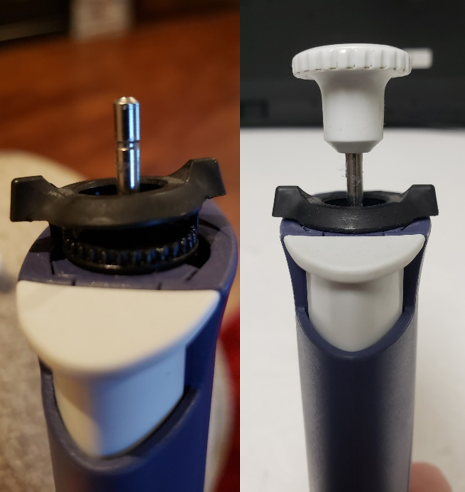
Category: Rainin/Mettler-Toledo

  • Preventive Maintenance: Rainin E4 XLS/XLS+ Single Channel – Piston Assembly

    The process of performing preventive maintenance (PM) on the E4 XLS/XLS+ requires great care, a high attention to detail, patience, and steady hands. Please dedicate a good work area with good lighting and space where small parts can be located should they fly out during disassembly. Pipette damage and lost parts may occur if attention to detail is not maintained. Please proceed at your own risk.

    Disclaimer: These instructions are only applicable for the Rainin E4 XLS if the pipette has been upgraded with the lip seal and black colored seal retainer. See this post for more information. The instructions are applicable for all E4 XLS+ pipettes.
    Recommended Supplies:
    1. Needle Nosed Pliers (to loosen piston assembly)
    2. Pipette Supplies 55g of Lip Seal Lubricant. Item# 2XLSGR55
    3. A box of kim wipes (to remove old lubricant from piston assembly)
    4. A bottle of 70% IPA (to clean piston assembly)
    5. Pair of laboratory gloves for PM process
    6. E4 XLS+ Single Channel Replacement Parts (as needed)
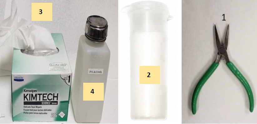
    Recommended supplies for E4 XLS preventative maintenance
    Step 1:

    Press and hold down the tip ejector button, as shown in Figure 1.0. This will cause the white colored E4 XLS tip ejector sleeve to be lowered for easier removal from the pipette body.
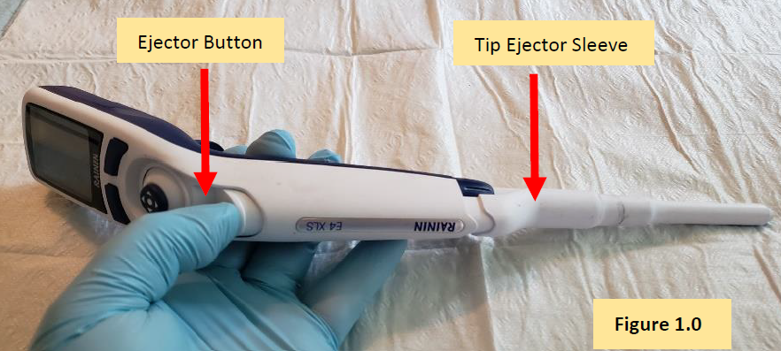
    Press E4 XLS ejector button
    Step 2:

    Slide off and disengage the tip ejector sleeve from the pipette body. Figure 1.1.
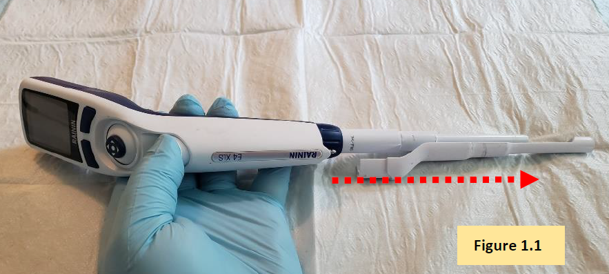
    Remove E4 XLS tip ejector
    Step 3:

    Turn the shaft coupling nut clockwise to remove the shaft from the pipette body. Figure 1.2.


    CAUTION: When unscrewing the coupling nut, there is an internal piston spring that is under tension. Caution is needed to prevent small parts from popping out from inside of the shaft. It’s strongly recommended to unscrew the coupling nut over a table.
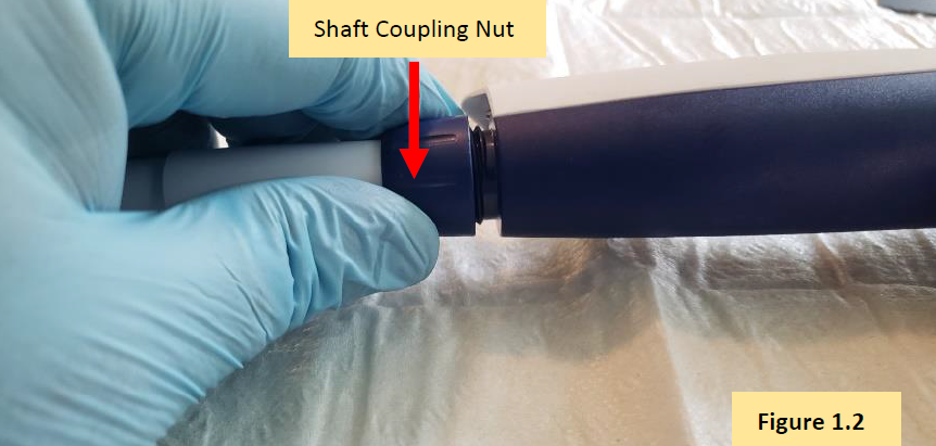
    Remove E4 XLS coupling nut

    COMMENT: With the shaft coupling nut disengaged from then pipette body, you will see the internal piston assembly, with spring. Figure 1.3.
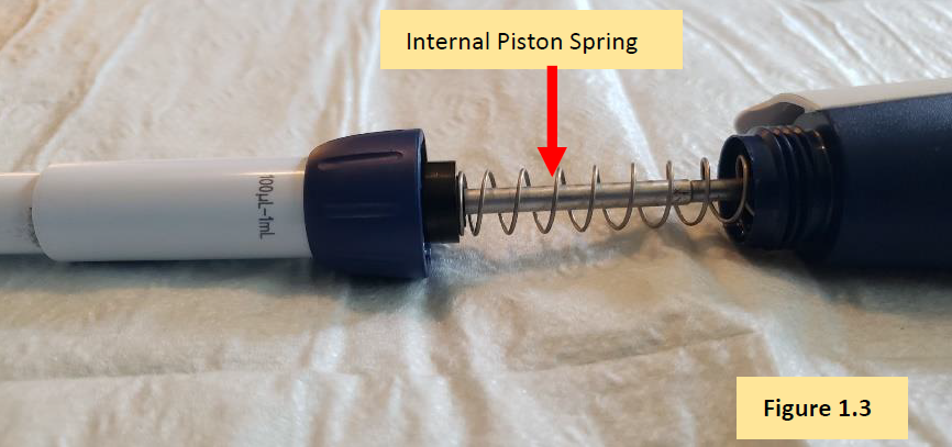
    Internal piston spring
    Step 4:

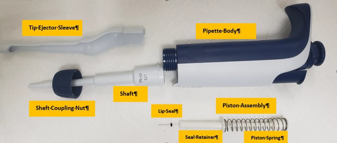
    Remove the shaft from the E4 XLS pipette body and fully expose the internal piston, spring, seal retainer, and lip seal. Figure 1.4.
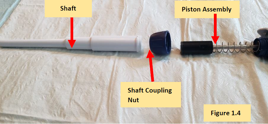
    Disassembled E4 XLS lower part
    Step 5:

    Locate and remove the lip seal from the piston assembly. Figure 1.5.
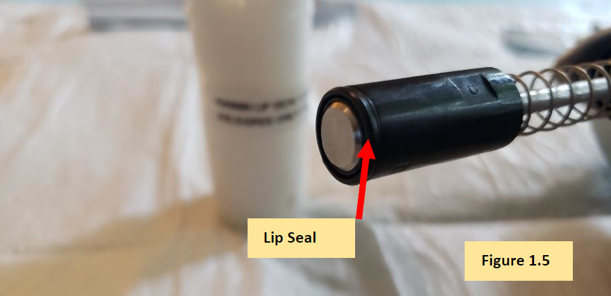
    Lip Seal

    COMMENT: With the lip seal removed, now the focus shifts to servicing the piston assembly.
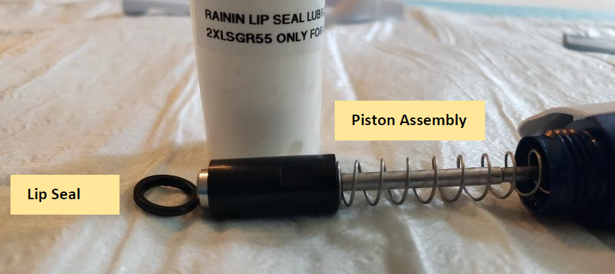
    E4 XLS piston assembly and lip seal

    COMMENT: Only, follow the next steps if the piston needs to be removed and/or replaced. If not, proceed to Step 7.


    Step 6:

    Collapse the piston spring with a gloved hand to expose the piston stem and motor spine connection. Figure 1.6.
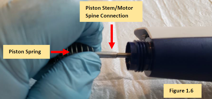
    Piston stem/motor spine connection
    Step 6.1:

    Unscrew the piston stem from the motor spine until it is fully detached. Figure 1.7.
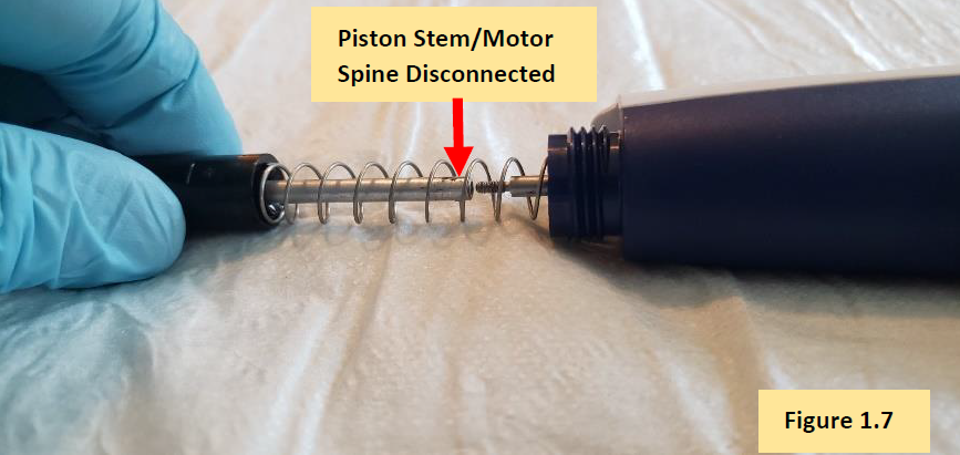
    Disconnected E4 XLS piston stem/motor spine
    Step 6.2:

    Slide and remove the piston spring from the piston spine, followed by removal of the black colored lip seal retainer. Figure 1.8.
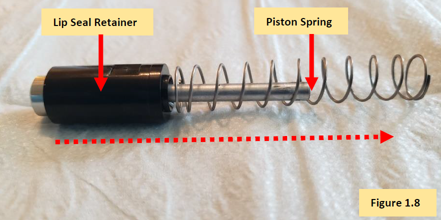
    Remove piston spring from piston spine
    Step 6.2 COMMENT:

    Figure 1.9 shows lip seal, piston, piston spring, and seal retainer removed from the motor spine.
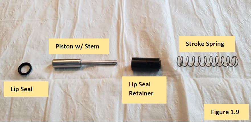
    Disassembled E4 XLS piston assembly
    Step 6.3:

    Clean and remove the old lip seal lubricant with 70% IPA and Kim Wipes. Once the E4 XLS piston is cleaned, use a foam swab to apply a light, but visible, coat of lip seal lubricant
    (Item# 2XLSGR55) to the piston.

    NOTE: It’s not necessary to lubricate the entire piston. Lubricate approximately 2/3 of the piston. Figure 2.0.
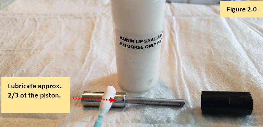
    Grease on E4 XLS piston
    Step 7.0:

    With a foam swab, Q-Tip, and IPA, clean inside of the shaft to remove any chemical splash, lubricant, etc. If needed, replace shaft. Figure 2.1.

    (See E4 XLS+ Single Channel Replacement Parts)
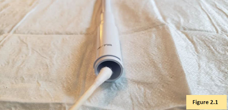
    Lubricating inside of tip cone
    Step 7.1:

    Install a new lip seal onto the piston. Figure 2.2. (See E4 XLS+ Single Channel Replacement Parts)
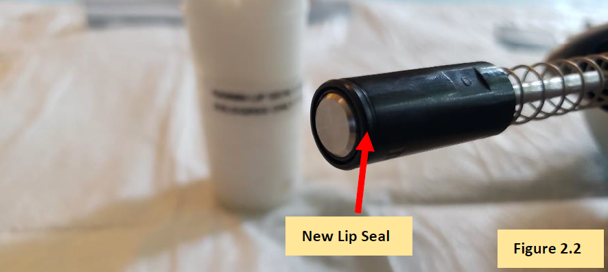
    New E4 XLS lip seal replacement
    Step 7.2:

    Affix and reattach the shaft to the shaft coupling nut. Figure 2.3.
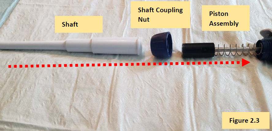
    reassembling the lower part
    Step 7.3:

    Screw the shaft coupling nut and shaft back onto the pipette body. Figure 2.4.
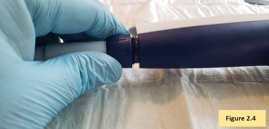
    Attaching the E4 XLS coupling nut
    Step 7.4:

    Press and hold down the tip ejector button to extend the tip ejector rod from the bottom of the pipette. Affix the tip ejector sleeve to the exposed tip ejector rod. Affix a pipette tip to the pipette and aspirate/dispense Di water to check for leaks. If a leak is detected, recheck work. If no leaks are detected, allow pipette to equilibrate for 1 hour.
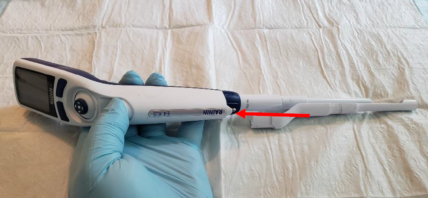
    Reattaching the tip ejector
    Step 7.5:

    After the 1-hour equilibration period has elapsed, check the E4 XLS pipette’s accuracy and precision performance on an analytical 4-5 place balance. Recheck work as needed.

    calibration with balance
    Related Posts:

    Seal/O-Ring Vs. Lip Seal for Pipet-Lite, Pipet-Lite XLS, and E4-XLS Models
    Rainin Pipette Legend
    Frequency of Pipette Preventative Maintenance and Calibration
    Top 10 Crimes Committed Against Pipettes

    Disclaimer: Any action you take using the information on this website is strictly at your own risk. The information herein does not constitute professional advice and is general in nature. We make no warranty that this information will meet your requirements, be safe, accurate, or error-free. Pipette Supplies, Inc. is not responsible for any errors or omissions, any results obtained from the use of this information, or any loss or damage arising out of the use of this information. This site is for educational purposes only.
    Fair Use: Copyright Disclaimer under section 107 of the Copyright Act of 1976, allows for “fair use” for purposes such as comments, criticism, teaching, scholarship, news reporting, and research.
    Fair use is permitted by copyright statute that might otherwise be infringing.
  • Gilson Microman / Microman E and RAININ Pos-D: Calibration Instructions

    Warning. Proceed at your own risk.

    The process of performing a Microman / Microman E / Pos-D calibration adjustment should always be the last option. Verifying that all other components are in good working condition and part replacement, as needed, should be done first. Pipette damage and lost parts may occur if attention to detail is not maintained. Please proceed at your own risk.

    Required Microman Calibration Adjustment Tool:
    Locking Cap Lever Tool – GI F148172

    NOTE: For illustration purposes, these instructions focus on the Gilson Microman. The instructions below and the locking cap lever tool can also be used with the Gilson Micronman E and Rainin Pos-D.

    Printable Calibration Log
    Printable Calibration Stickers (for use with Avery 5960 labels)

    Microman Calibration Instructions
    Step 1:

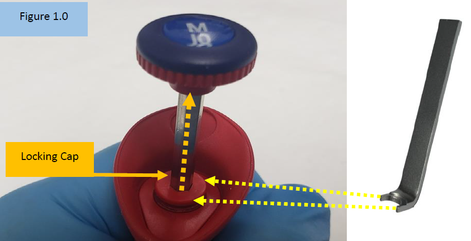
    Insert the open end of the Locking Cap Lever Tool into the Microman locking cap. Figure 1.0.
    Once inserted into the locking cap, pry the locking cap upward.

    Insert tool into locking cap
    Step 2:

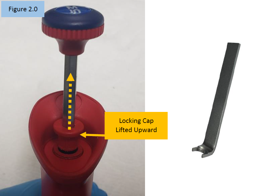
    Notice the locking cap is now lifted upward and out of the pipette body.


    CAUTION: With the locking cap now lifted upward, any movement of the adjustment knob will affect the calibration.

    Lift locking cap upward
    Step 3:

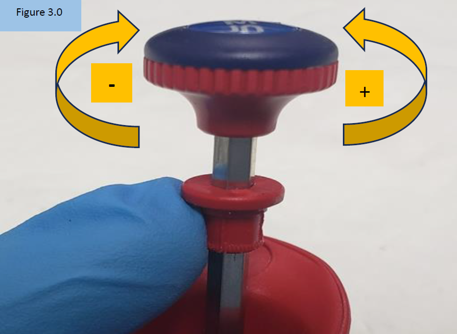
    Rotate the adjustment knob:

    A. Counter-clockwise to increase the volume aspirated and dispensed ( + )
    B. Clock-wide to decrease the volume aspirated and dispensed ( – ), Figure 3.0

    NOTE: Only turn the adjustment knob 1/8th of a turn at a time. Large turns will grossly affect desired results. For best results, it’s recommended to make adjustments at the 10% volume.

    Microman calibration adjustment knob turning
    Step 4:

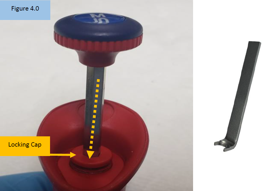
    Insert the open end of the Locking Cap Lever Tool into the Microman locking cap. Push it back down into the body opening until it clicks back into place. Ensure it is fully in place. Figure 4.0.

    Microman calibration - adjustment knob Locking cap seated
    Step 5:

    Check the calibration adjustment made on a 4-5 place analytical balance. Repeat steps 1-5 if additional calibration adjustment is needed.

    Related Posts:
    Gilson Microman Inspection, Spring/Clamp Replacement, and Preventive Maintenance
    Gilson Pipette Legend
    Rainin Pipette Legend

    Disclaimer: Any action you take using the information on this website is strictly at your own risk. The information herein does not constitute professional advice and is general in nature. We make no warranty that this information will meet your requirements, be safe, accurate, or error-free. Pipette Supplies, Inc. is not responsible for any errors or omissions, any results obtained from the use of this information, or any loss or damage arising out of the use of this information. This site is for educational purposes only.
    Fair Use: Copyright Disclaimer under section 107 of the Copyright Act of 1976, allows for “fair use” for purposes such as comments, criticism, teaching, scholarship, news reporting, and research.
    Fair use is permitted by copyright statute that might otherwise be infringing.
  • Push Rod Ejector Assembly Replacement for the Pipet-Lite XLS/XLS+

    The process of removing, replacing, and reinstalling the Pipet-Lite XLS push rod ejector assembly requires great care, a high attention to detail, patience, and steady hands. Please dedicate a good work area with good lighting and space where small parts can be located should they pop/fly out during disassembly. Pipette damage and lost parts may occur if attention to detail is not maintained. Please proceed at your own risk.

    Recommended Service Tools

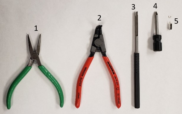
    The following tools pictured here are highly recommended to properly service, repair, or replace the push rod ejector assembly, and/or internal volume assembly.

    1. Needle Nose Pliers
      Catalog #: Source Locally
    2. Bent Nosed Pliers
      Catalog #: PS 10007
    3. C-Clip Installation Tool
      Catalog #: PS 10005N
    4. C-Clip Removal Tool
      Catalog # PS 10006N
    5. Replacement C-Clips
      Catalog # PS 1555C (10pk)

    Pipet-Lite XLS / XLS+ Ejector Push Rod Assembly: Part # RA 17012080.

    These instructions are only applicable for the Pipet-Lite XLS and XLS+. If you have a Pipet-Lite (not XLS) you can find similar instructions here.

    Required tools for Pipet-Lite XLS push rod ejector assembly maintenance

    Push Rod Ejector Disassembly Instructions: PIPET-LITE XLS/XLS+

    Step 1:

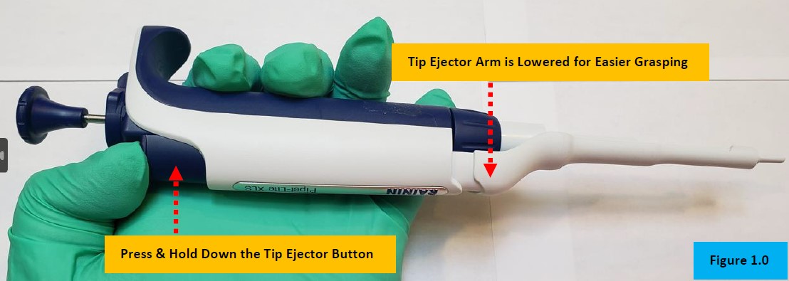
    Press and hold down the tip ejector button for easier removal of tip ejector sleeve, as shown in Figure 1.0.

    Figure 1.0. Removing the ejector sleeve
    Step 2:

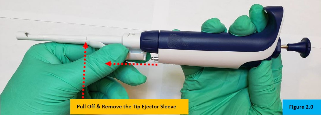
    Firmly grasp the tip ejector sleeve and gently pull it in the opposite direction of the pipette handle/body, as shown in Figure 2.0. Lay a side for reassembly.

    Figure 2.0. removing ejector sleeve off of the Pipet-Lite XLS Push Rod Ejector

    CAUTION: There is a spring and small parts under tension inside of the lower shaft assembly. Use caution as small parts may fly off when the lower shaft is separated from the pipette body.This image has an empty alt attribute; its file name is image-13.png

    Warning
    Step 3:

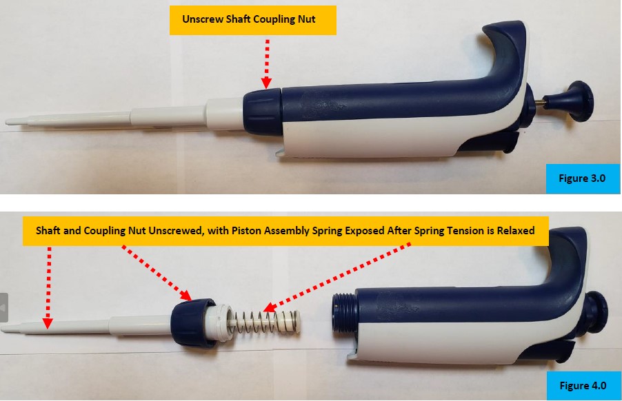
    Gently unscrew the shaft coupling nut to separate the lower shaft assembly from the pipette body/handle. See Figure 3.0 & 4.0.

    Lip Seal Lubricant Catalog # 2XLSGR55 used to lubricate piston assembly for pipettes with Lip Seals.

    Figure 3.0. Unscrew shaft coupling
Figure 4.0 piston assembly exposed

    NOTE: At this point, routine preventative maintenance (PM) of the piston, spring, seal, o-ring, and shaft components can be performed, if desired.

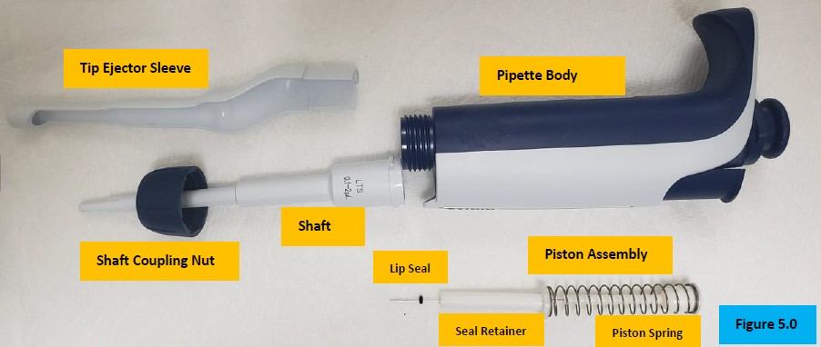
    Inspect, clean, lubricate, and/or replace the piston assembly as needed. Examine and replace the seal and o-ring as part of the PM. Inspect and clean the inside of the shaft, and/or replace as needed. Figure 5.0.

    Figure 5.0. Disassembled Pipet-Lite XLS
    Step 4:

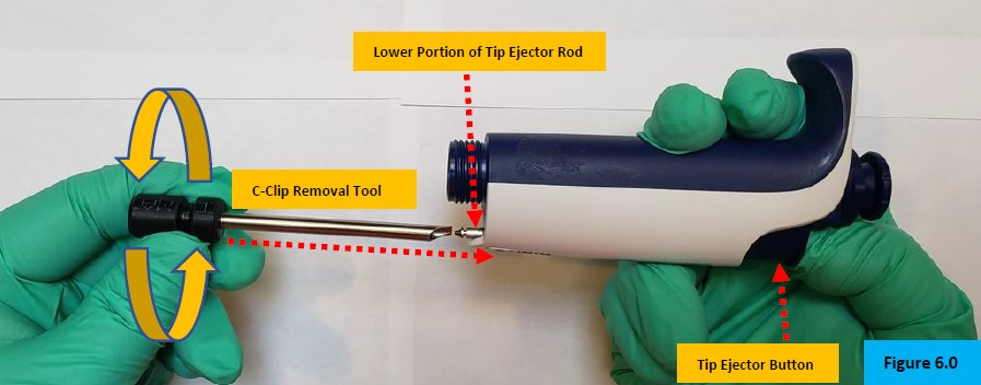
    Press and hold down the tip ejector button to expose the lower point of the tip ejector rod, as shown in Figure 6.0.

    Step 5:

    Slide the C-Clip removal tool onto the ejector rod and firmly push it inward to contact the c-clip(s) that are attached to the ejector rod assembly. Push firmly and twist the tool to dislodge the c-clip(s). Figure 6.0. You may need to do this a couple of times before the clip comes off.

    Figure 6.0. Removal of c-clip using tool on the Pipet-Lite XLS Push Rod Ejector

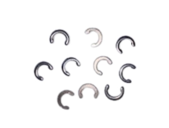
    CAUTION: When the c-clips are removed, they may fly off and can easily be lost. Having extra c-clips on hand is highly recommended. Catalog #: PS 1555C (10pk)

    C-clips

    Pipet-Lite XLS Push Rod Ejector Assembly – Removal & Access to the Volume/Counter Assembly

    Step 6:

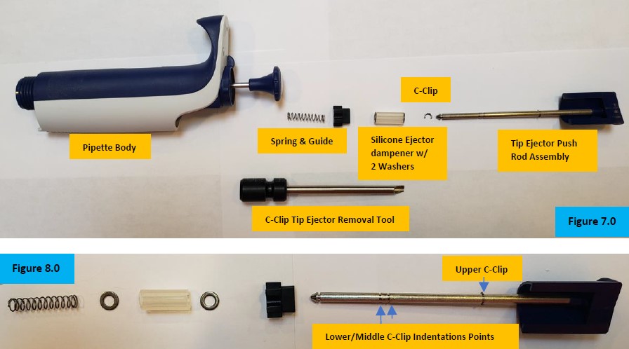
    Grasp the tip ejector button and firmly pull upward to remove the tip ejector rod assembly from the top of the pipette body. Put aside for reassembly. Take notice of the parts and their orientation for reassembly. See Figure 7.0 & 8.0.

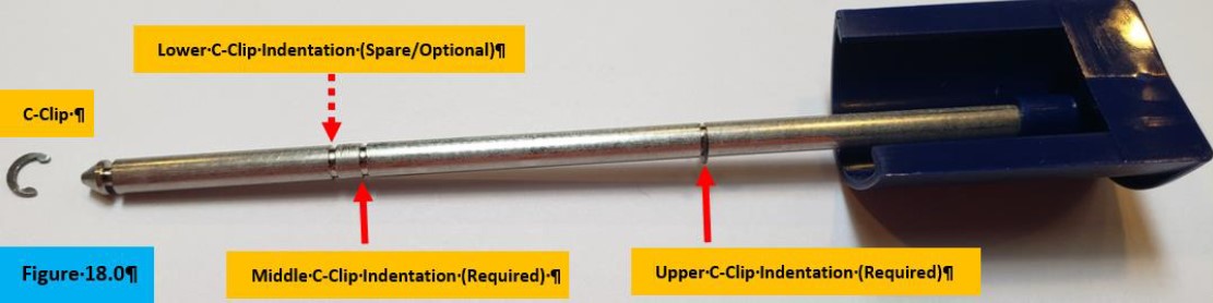
    NOTE: Take notice of the lower, middle, & upper indentations where the c-clips will be re-installed later. Upper c-clip is installed for visual. Figure 8.0.

    Figure 7.0 disassembled ejector assembly
Figure 8.0 c-clip indentions on Pipet-Lite XLS Push Rod Ejector.
    Step 7:

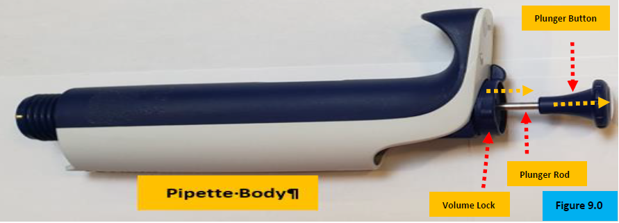
    Grasp and firmly pull upward to remove the plunger button. Lay aside. Figure 9.0.

    Figure 9.0. Plunger button/rod, volume lock
    Step 8:

    With a small-bladed, flathead screwdriver, gently pry up the volume lock wing to remove the volume lock. Lay it aside.

    Step 9:

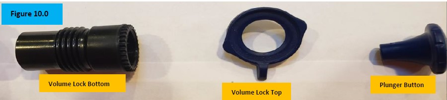
    Unscrew fully and remove the volume lock bottom from inside the pipette body. Figure 10.0.

    Figure 10.0. Disassembled volume lock after removal of Pipet-Lite XLS Push Rod Ejector

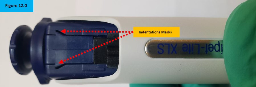
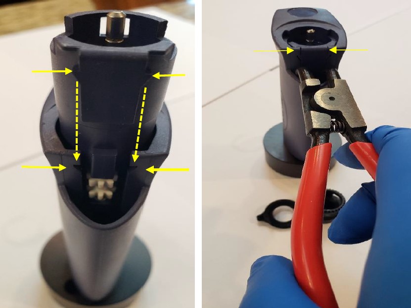
    NOTE: Notice the points on the internal volume assembly. These indentations hold the internal volume assembly in place while under tension. These indentations will be spread apart with the bent nosed pliers to remove the internal volume/counter assembly from the pipette body. Figure 12.0.

    Figure 12.0 Intention marks for the bent-nosed pliers.
    Step 10:

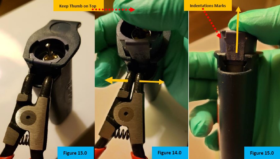
    Insert the bent-nosed pliers into the opening vacated by the push rod tip ejector. See Figure 13.0.


    CAUTION: Place thumb on top of the volume assembly prior to step 11. DO NOT REMOVE thumb or internal contents will fly out when step 11 is performed. Figure 14.0.

    Figure 13.0-15.0. Using bent nosed pliers to remove the volume assembly after removing the Pipet-Lite XLS Push Rod Ejector
    Step 11:

    Gently squeeze the handle of the bent-nosed pliers to have the internal volume assembly pop out of the pipette. Figure 14.0.

    Step 12:

    Remove the bent-nosed pliers from the pipette body. Ejected Internal volume assembly is now accessible. Figure 15.0.

    Step 13:

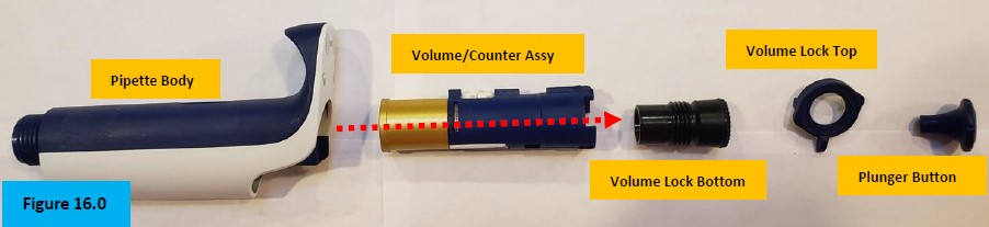
    Slide the internal volume/counter assembly out of the pipette. Figure 16.0.

    NOTE: The plunger button, volume lock, & volume lock bottom are shown for orientation purposes. The plunger rod and internal spring are not shown in Figure 16.0.

    Figure 16. Volume assembly and volume lock disassembled.
    Step 14:

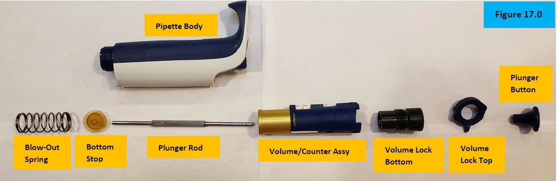
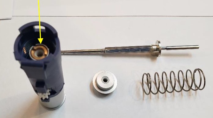
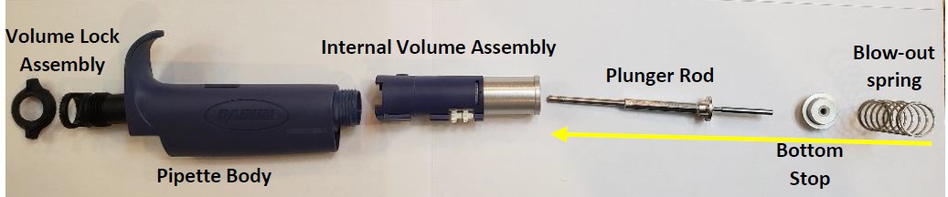
    Slide out and remove the plunger rod, internal blowout spring, and bottom stop from the pipette body. Figure 17.0.

    NOTE: Parts are displayed in their proper orientation for reassembly. Figure 17.0

    Figure 17.0. Disassembled internal components of Pipet-Lite XLS/XLS+
    Step 15:

    Replace or repair internal volume assembly, plunger rod, bottom stop, and/or blow-out spring.

    REASSEMBLY and Use of C-Clip Installation Tool

    Step 16:

    (1) Insert and screw the volume lock bottom back into the volume assembly.

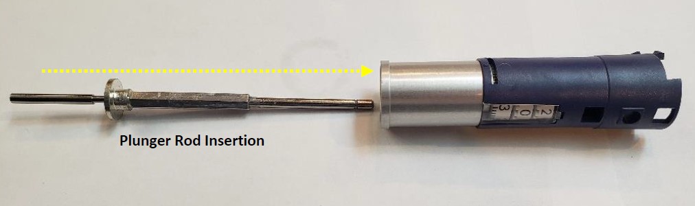
    (2) Insert the plunger rod back into the bottom opening of the volume assembly.

    (3) Install the bottom stop onto the plunger rod.

    (4) Install the blow-out spring onto the bottom stop.

    (5) Insert these components into the pipette body opening, spring first.

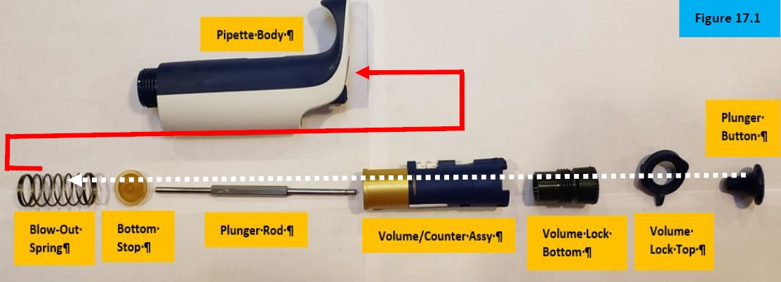
    (6) Install the volume lock top. Wait to install the plunger button until the lower shaft is installed back onto the pipette. Figure 17.1.

    Figure 17.1. Disassembled pipette body of Pipet-Lite XLS

    NOTE: Notice the c-clip and 3 indentation marks on the tip ejector rod. A minimum of 2 c-clips are needed for reassembly. The 3rd is optional and, on some occasions, is installed for additional support, or as a spare. Figure 18.0

    Figure 18.0. C-clip indentations on the Pipet-Lite XLS Push Rod Ejector

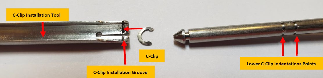
    Notice the indentation on the C-Clip installation tool. This is where the c-clip must be installed into for reassembly back onto the push rod ejector assembly.

    C-clip tool and ejector rod

    ** Step 17-19B will be completed after Step 22. They are shown below to illustrate the process and allow you to practice. Review these steps first and then return after step 22.**

    Step 17:

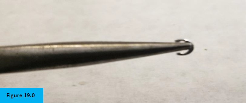
    With your needle nose pliers, install the c-clip onto it as shown. Figure 19.0

    Figure 19.0. Needle nose pliers holding c-clip for installation in tool.
    Step 18:

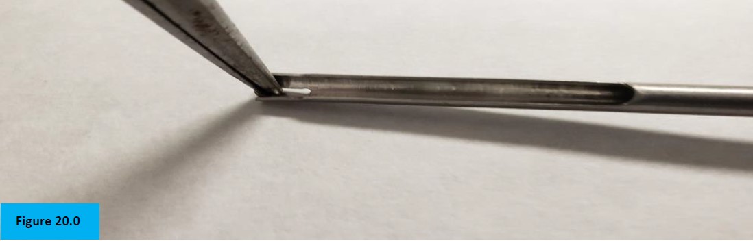
    Insert the c-clip into the grooved indentation of the c-clip Installation Tool. Figure 20.0.

    NOTE: This is being illustrated for easier viewing. Step would not occur until the push rod ejector assembly is reinstalled into the pipette body.

    Figure 20.0. C-clip installation into tool.
    Step 19:

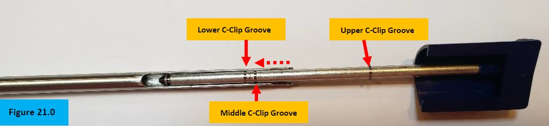
    Slide the c-clip installation tool slightly past the middle c-clip insertion groove. Next, drag the tool gently backwards until the c-clip contacts the middle insertion groove. Snap the c-clip in place with the tool. Figure 21.0.

    Step 19A:

    Install another c-clip onto the c-clip installation tool as described in steps 17-18 above.

    Figure 21.0. Different c-clip grooves on Pipet-Lite XLS Push Rod Ejector
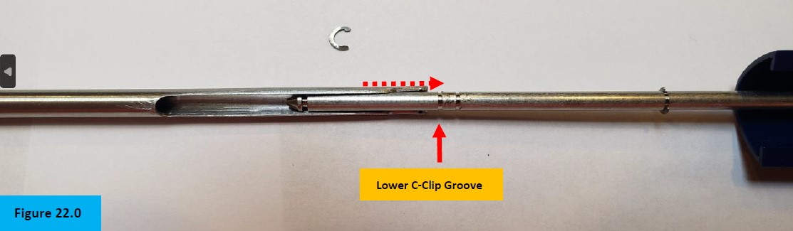
    Step 19B:

    Slide the c-clip installation tool to the lower c-clip groove and snap the c-clip in place. Figure 22.0.

    Figure 22.0. Lower c-clip groove on the Pipet-Lite XLS push rod ejector.

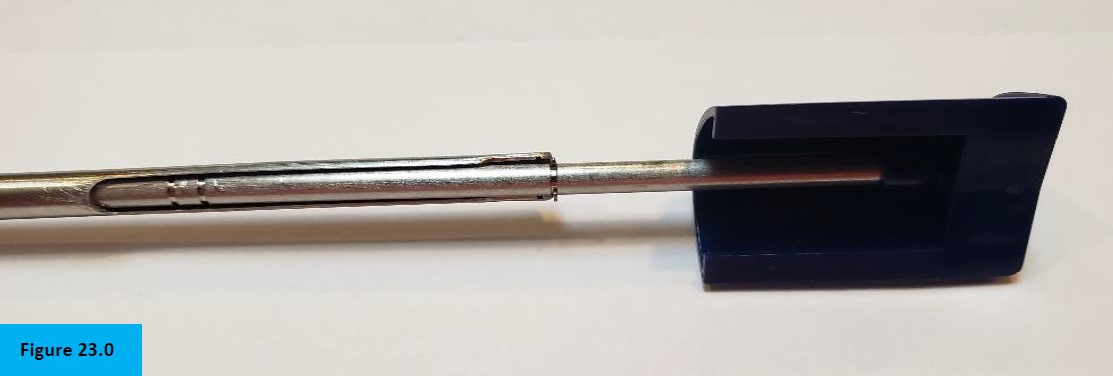
    ONLY IF NEEDED: Figure 23.0, the upper c-clip can be re-installed only after the spring, 2 washers, silicone dampener, ejector guide, & lower/middle c-clips are removed. Figure 23.1.

    Figure 23.0 c-clip installation tool in action on the Pipet-Lite XLS Push Rod Ejector.
    Figure 23.1 Pipet Lite XLS/XLS+ Ejector assembly disassembled
    Step 20:

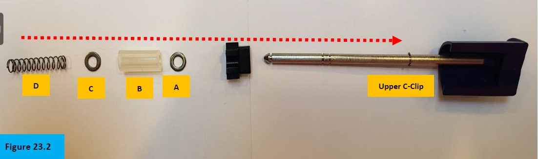
    Figure 23.2, Install part (A) onto the Pipet-Lite XLS push rod ejector until butted up to the upper c-clip. Install part (B), followed by part (C) until butted up next to part A. Install part (D) until butted up next to part (C).

    Figure 23.2. Order of parts on the Pipet-Lite XLS ejector rod.

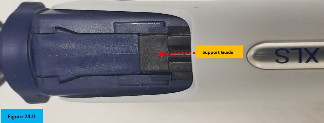
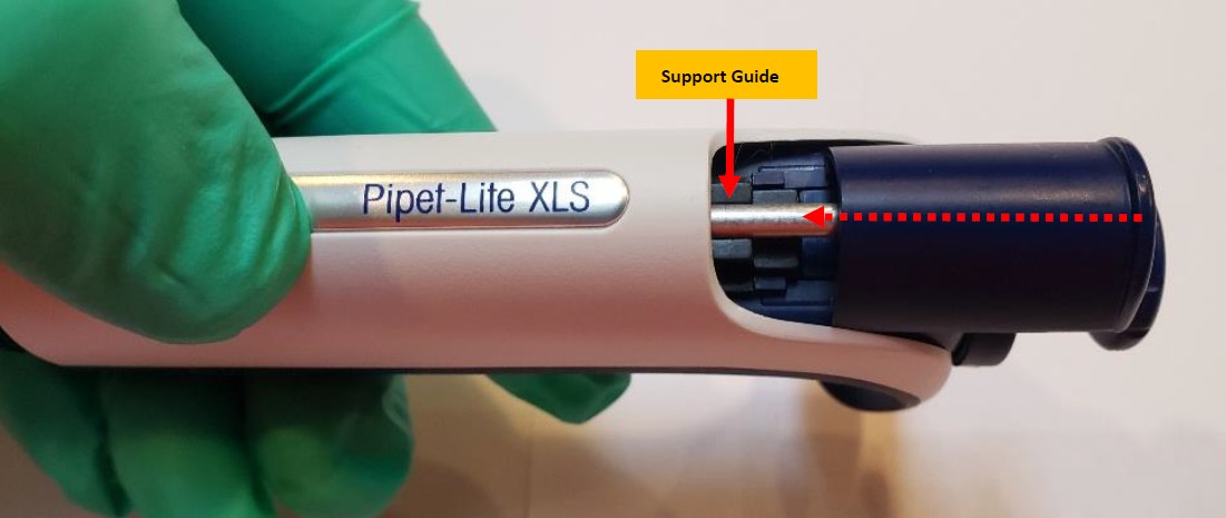
    NOTE: The support guide will be installed just prior to inserting the ejector rod assembly back into the pipette body. Notice the orientation and how it sits in the body. Figure 24.0.

    Figure 24.0 - Support guide
    Step 21:

    Install all components in order, as shown in Figure 23.2.

    Step 22:

    Just before inserting all components fully into the body, gently align and install the support guide to seat it, prior to pressing the tip ejector button down. When pressing the tip ejector button down, all parts will seat properly and then allow for the c-clips to be re-installed as stated in Steps 17 to Steps 19B. Figures 19.0 – 23.0.

    Support guide with ejector rod
    Step 23:

    Insert the piston assembly back into the shaft and screw the shaft coupling nut back onto the pipette body. Reattach the tip ejector arm back onto the pipette body. Reassemble the pipette liquid end assembly and allow to equilibrate for at least 60 minutes. Check functionality, accuracy, and precision performance on a 4-5 place balance. You have now completed the Pipet-Lite XLS Push Rod Ejector removal/installation instructions.

    Disassembled Pipet-Lite XLS/XLS+ lower part

    Related Posts:
    Rainin Pipet Lite XLS/XLS+ and Pipet-Lite Models: Counter Assembly Replacement
    Push Rod Ejector Assembly Replacement: Pipet-Lite, Pipet-Plus, EDP1, EDP3, Rainin Classic
    Rainin Pipet-Lite, XLS, XLS+ Single Channel Pipettes: How to Perform Liquid End Assembly Preventive Maintenance
    Rainin Pipet-Lite, Pipet-Lite XLS: How to Tighten a Loose Volume Lock Top
    Seal/O-Ring Vs. Lip Seal for Pipet-Lite, Pipet-Lite XLS, and E4-XLS Models

    Disclaimer: Any action you take using the information on this website is strictly at your own risk. The information herein does not constitute professional advice and is general in nature. We make no warranty that this information will meet your requirements, be safe, accurate, or error-free. Pipette Supplies, Inc. is not responsible for any errors or omissions, any results obtained from the use of this information, or any loss or damage arising out of the use of this information. This site is for educational purposes only.
    Fair Use: Copyright Disclaimer under section 107 of the Copyright Act of 1976, allows for “fair use” for purposes such as comments, criticism, teaching, scholarship, news reporting, and research.
    Fair use is permitted by copyright statute that might otherwise be infringing.
  • Rainin Pipet Lite XLS/XLS+ and Pipet-Lite Models: Counter Assembly Replacement

    Warning

    The process of removing, replacing, and reinstalling the Rainin Pipet-Lite/Pipet-Lite XLS/PIpet-Lite XLS+ Counter Assembly requires great care, a high attention to detail, patience, and steady hands. Please dedicate a good work area with good lighting and space where small parts can be located should they pop/fly out during disassembly. Pipette damage and lost parts may occur if attention to detail is not maintained. Please proceed at your own risk.

    Recommended Service Tools

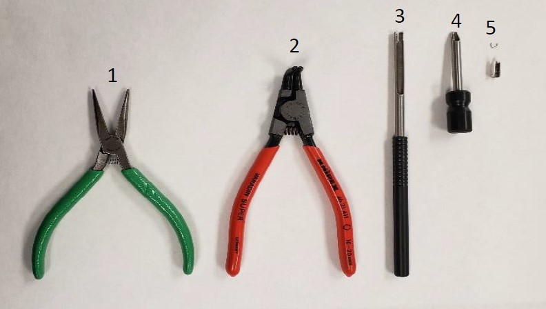
    The following tools are strongly recommended to properly service, repair, or replace the Rainin push rod ejector assembly and/or the internal volume assembly.

    1. Needle Nose Pliers
    2. Bent Nosed Pliers: PS 10007
    3. C-Clip Insertion Tool: PS 10005N
    4. C-Clip Removal Tool: PS 10006N
    5. Replacement C-Clips: PS 1555C
    Recommended tools for Pipet-Lite Counter Assembly Replacement

    Pipet-Lite/Pipet-Lite XLS/Pipet-Lite XLS+ Counter Assembly Replacement

    **NOTE: Pipette Supplies does not currently sell the Pipet-Lite counter assemblies or body retainer assemblies.**

    Step 1:

    Complete Rainin Push Rod Ejector Assembly Replacement through Step 8.

    Step 2:

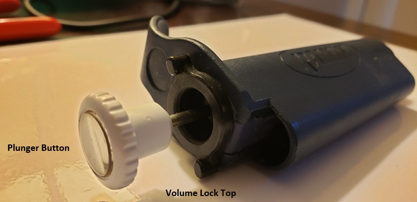
    Remove the plunger button, volume lock top, and volume lock bottom from the pipette handle. The plunger button and volume lock top can be pulled directly off the pipette.

    Plunger button and volume lock top
    Step 3:

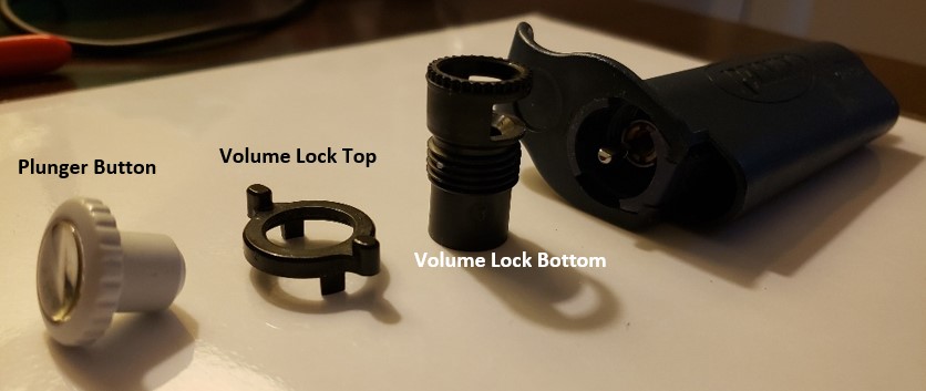
    Unscrew the volume lock bottom and remove it from the pipette body.

    Plunger button, volume lock top, volume lock bottom
    Step 4:

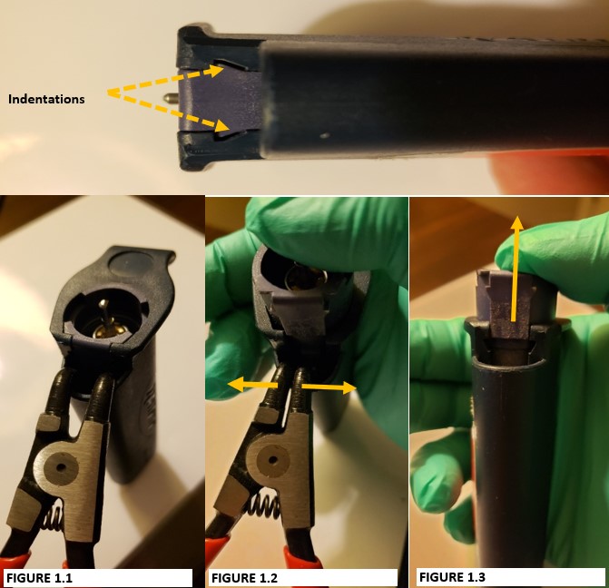
    Notice the indentations on the internal volume assembly. These indentations will be spread apart with the bent-nosed pliers to remove the internal volume assembly from the pipette body.

    CAUTION: Place your thumb on top of the volume assembly prior to step 5. DO NOT remove your thumb or internal contents will fly out when step 5 is performed.

    Step 5:

    Insert the bent-nosed pliers into the opening that is vacated by the tip ejector button (Figure 1.1). Gently squeeze the handle of the bent-nosed pliers to have the internal volume assembly pop out of the pipette (Figure 1.2).

    Step 6:

    Remove the bent-nosed pliers from the pipette body. Internal volume assembly is now accessible as in figure 1.3

    Use the bent nose pliers to release the volume assembly from the pipette
    Step 7:

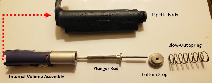
    With the internal volume assembly removed from the pipette, remove the:

    1. Blow-out spring from the pipette body
    2. Bottom stop
    3. Plunger rod
    Disassembled pipette including: volume assembly, plunger rod, bottom stop, blow out spring
    Step 8:

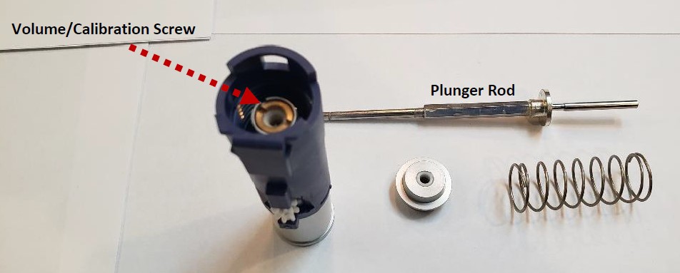
    Notice the volume/calibration screw seated in the volume assembly. This will be removed next with the plunger rod.

    calibration screw in volume assembly

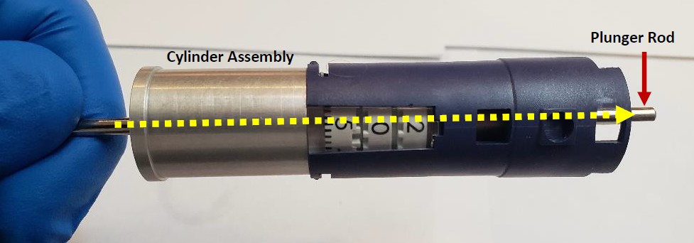
    Insert the plunger rod fully into the bottom (silver colored) cylinder assembly until the plunger rod is visible from the top of the volume assembly as shown below.

    plunger rod through cylinder assembly and volume assembly
    Step 9:

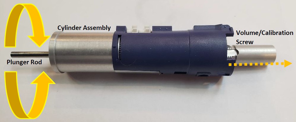
    Rotate the plunger rod (the display digits will wind upwards) until the silver/brass colored volume/calibration screw disconnects and can be removed by hand.


    NOTE: Remember to write down the digits of the Pipet-Lite counter assembly once the volume/calibration screw is removed. This information will be useful during reassembly.

    twist plunger rod

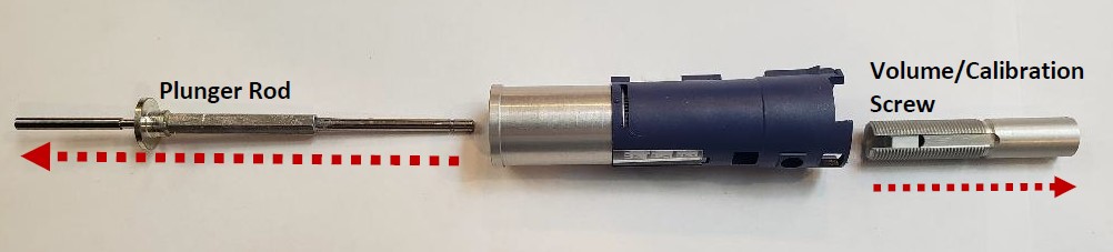
    The picture below shows the volume calibration screw fully removed from the top of the pipette, and plunger rod removed from the bottom of the pipette.

    plunger rod and volume screw
    Step 10:

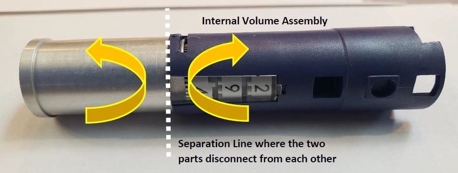
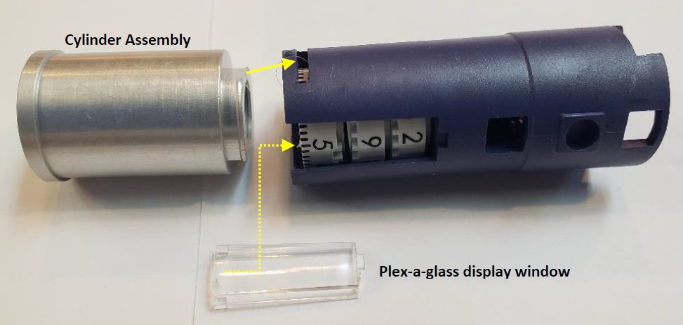
    In this step, the silver cylinder assembly will be separated and removed from the volume assembly. Place the cylinder assembly in the left hand and the volume assembly in the right hand. With your thumbs, gently push upward to separate these two parts from each other

    separation line where two parts disconnect
    Step 11:

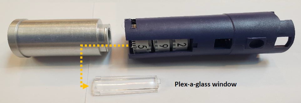
    Slide the display plex-a-glass window out.

    disassembled glass window
    Step 12:

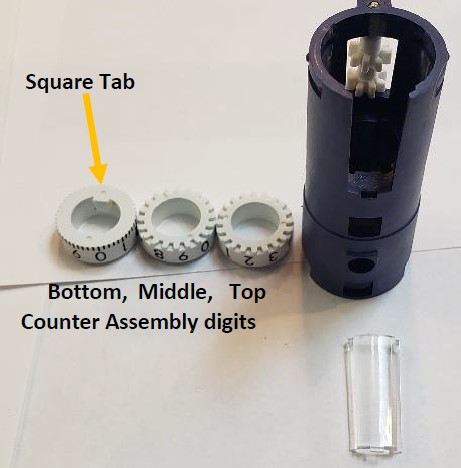
    Turn the volume assembly vertically and remove the three (3) white colored digits.


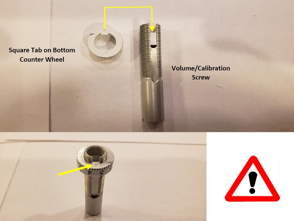
    NOTE: Notice the square tab on the bottom digit. This will be important for reassembly of the volume/calibration screw.

    disassembled body and counter wheels. Pipet-Lite Counter Assembly

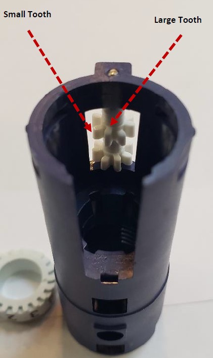
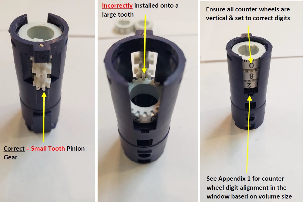
    NOTE: During reassembly of the Pipet-Lite counter assembly digits, the top and middle digits will need to be placed on a “small tooth”. DO NOT align them on a “large tooth” as this could lead to the digits not aligning fully in a straight line.

    small tooth vs large tooth on the Pipet-Lite Counter Assembly
    Step 13:

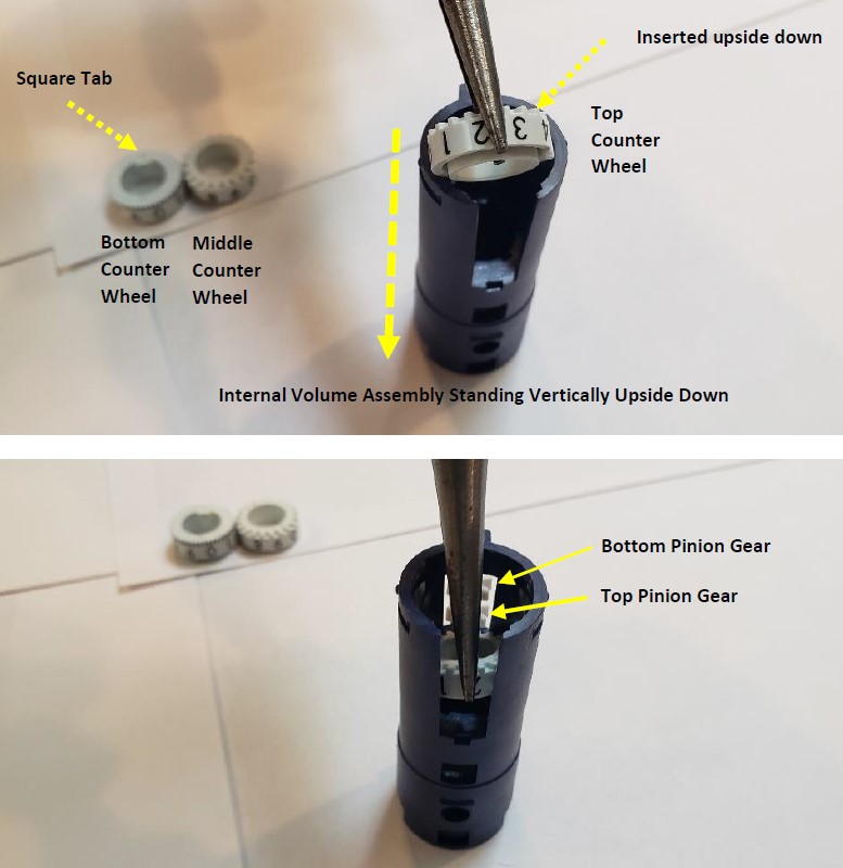
    With the counter assembly standing vertically upside down, use a pair of needle nose pliers to insert:

    1. The top counter wheel first onto the top pinion gear “small tooth”
    2. insert the middle counter wheel onto the bottom pinion gear “small tooth”
    3. insert/lay the bottom counter wheel on top of the middle counter wheel

    IMPORTANT: The top and middle counter wheels must be inserted into the volume assembly upside down and seat onto a “small pinion gear tooth,” as shown.

    Inserting counter wheels in the Pipet-Lite Counter Assembly

    IMPORTANT: when inserting the counter wheels, ensure the correct digits are visible in the window based on
    pipette volume size. See Appendix 1

    installed counter wheels in the Pipet-Lite Counter Assembly
    Step 14:

    Insert the display window back into the volume assembly. Install and snap the silver cylinder assembly back onto the volume assembly.

    Insertion of volume assembly and cylinder back onto volume assembly
    Step 15:

    Notice the volume/calibration screw and the square tab on the bottom counter wheel. The square tab must align with the slot track on the volume/calibration screw.

    alignment of square tab and slot track
    Step 16:

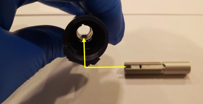
    In this step, the volume/calibration screw will be re-inserted into the internal volume assembly.

    IMPORTANT: Look down inside the volume assembly and align the volume/calibration screw with the square tab on the bottom counter wheel.

    Align volume screw with square tab

    Fully insert the volume/calibration screw into the internal volume assembly. Make sure it is inserted fully.

    disassembled view, insert volume screw into body
    Step 17:

    Insert the plunger rod fully into the bottom of the pipette through the silver cylinder assembly.

    Once fully inserted, wind the plunger so the volume of the counter wheels wind down to the 10% of nominal.

    It’s strongly recommended the internal volume assembly be rotated vertically so the calibration screw is threaded fully into the unit.

    plunger rod insertion
    Step 18:

    Place the bottom stop onto the plunger rod. Insert the blow-out spring down inside the empty pipette body. Install the plunger rod into the internal volume assembly.

    disassembled pipette including the Pipet-Lite Counter Assembly
    Step 19:

    Notice the pointed edges of the internal volume assembly. Using the bent nosed pliers, gently spread and enlarge the body opening, while pushing down on the internal volume assembly to align and lock it in the pipette body.

    use bent nose pliers to open body of pipette and access the inside of the Pipet-Lite Counter Assembly
    Step 20:

    Insert the volume lock bottom into the pipette body and screw it only finger tight. DO NOT over tighten or it will take much more force to lock and unlock the volume lock. Next, snap the volume lock top back onto the pipette.

    Place the plunger button back on the pipette.

    Screw the shaft assembly back onto the pipette body.

    reinsert the volume lock and screw tight
    Step 21:

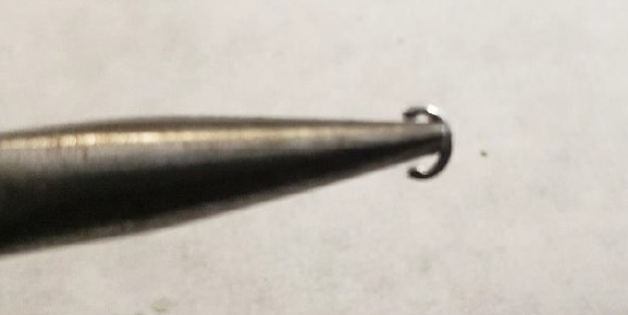
    With the needle-nosed pliers, gently grab and hold a c-clip onto the nubs of the pliers as shown in the photo below.

    hold c-clip with pliers
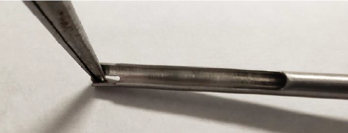
    Step 22:

    Insert the c-clip into the grooved indentation on the c-clip installation tool.

    insertion of c-clip
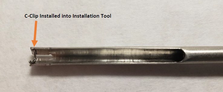
    Step 23:

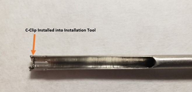
    Notice the c-clip inserted into the grooved indentation on the c-clip installation tool.

    c-clip installed into installation tool
    Step 24:

    Push and hold the ejector button. Gently slide the installation tool fully into the pointed end of push rod ejector rod assembly until the c-clip catches with the c-clip grooved indentation on the push rod ejector assembly as shown in the
    picture on step 8 of Rainin Push Rod Ejector Assembly Replacement.

    Step 25:

    Push the c-clip tool upward to snap the c-clip back in place until you hear a slight click.

    Step 26:

    Reattach the tip ejector arm back onto the pipette body.

    Step 27:

    Recheck your work and correct as needed.

    snap c-clip back in place with installation tool
    Appendix 1:

    Disclaimer: Any action you take using the information on this website is strictly at your own risk. The information herein does not constitute professional advice and is general in nature. We make no warranty that this information will meet your requirements, be safe, accurate, or error-free. Pipette Supplies, Inc. is not responsible for any errors or omissions, any results obtained from the use of this information, or any loss or damage arising out of the use of this information. This site is for educational purposes only.
    Fair Use: Copyright Disclaimer under section 107 of the Copyright Act of 1976, allows for “fair use” for purposes such as comments, criticism, teaching, scholarship, news reporting, and research.
    Fair use is permitted by copyright statute that might otherwise be infringing.
  • Push Rod Ejector Assembly Replacement: Pipet-Lite, Pipet-Plus, EDP1, EDP3, Rainin Classic

    Warning

    The process of removing, replacing, and reinstalling the Rainin Push Rod Ejector Assembly requires great care, a high attention to detail, patience, and steady hands. Please dedicate a good work area with good lighting and space where small parts can be located should they pop/fly out during disassembly. Pipette damage and lost parts may occur if attention to detail is not maintained. Please proceed at your own risk.

    These instructions are applicable for the following pipettes (single and multichannel):

    • Pipet-Lite (NOT APPLICABLE FOR PIPET-LITE XLS/XLS+. For Pipet-Lite XLS instructions, click here) (Ejector button not sold by Pipette Supplies)
    • Pipet-Plus (Different ejector button, not sold by Pipette Supplies)
    • EDP1 (Different ejector button, not sold by Pipette Supplies)
    • EDP3 (Different ejector button, not sold by Pipette Supplies)
    • RAININ Classic (Different ejector button, not sold by Pipette Supplies)
    Recommended Service Tools

    The following tools pictured here are strongly recommended to properly service, repair, or replace the Rainin push rod ejector assembly and/or the internal volume assembly.

    1. Needle Nose Pliers
    2. Bent Nosed Pliers: PS 10007 (Only required if completing the optional counter assembly replacement instructions)
    3. C-Clip Insertion Tool: PS 10005
    4. C-Clip Removal Tool: PS 10006
    5. Replacement C-Clips: PS 1555C

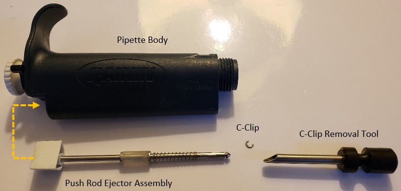
    Pipette Supplies does not current sell replacement Rainin Pipet-Lite (NON-XLS) Push Rod Ejector Assemblies.

    Recommended tools for Rainin Push Rod Ejector Assembly Replacement

    Rainin Push Rod Ejector Disassembly Instructions

    Step 1:

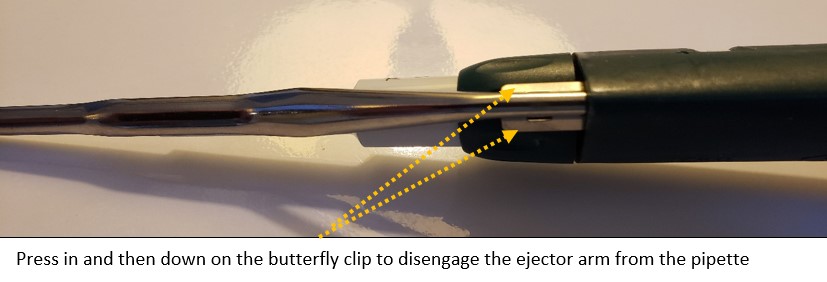
    Remove the tip ejector arm from the pipette by pressing in and down on the butterfly clips. Once removed, lay the tip ejector arm aside for reassembly later.

    Press in and then down on the butterfly clip to disengage the Rainin ejector arm from the pipette
    Step 2:

    Unscrew the shaft coupling nut. Remove the shaft and internal piston assembly.

    CAUTION: Be careful when unscrewing the coupling nut. The piston spring is under tension and may fly out with the piston assembly parts.

    Lay the piston assembly, shaft, and shaft coupling nut next to the tip ejector arm for reassembly later.

    disassembled pipette, not including ejector assembly
    Step 3:

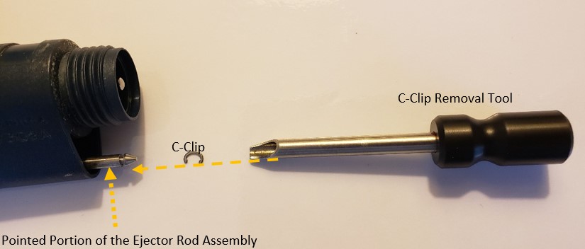
    Locate the C-Clip removal tool. The C-Clip is the part that will be removed by the removal tool in step 4. Be careful to not lose the c-clip when removed, it can easily fly out of the pipette.

    Step 4:

    Press and hold down the tip ejector button to partially expose the pointed portion of the push rod assembly from the pipette body.

    C-Clip removal tool and C-Clip, pointed portion of the ejector rod assembly
    Step 5:

    Fully insert the c-clip removal tool into the pointed portion of the push rod ejector assembly.

    Step 6:

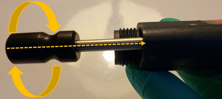
    Once the c-clip removal tool is fully inserted into the Rainin push rod ejector assembly, twist the c-clip removal tool handle to dislodge the c-clip from the push rod ejector assembly. Begin by turning gently and then gradually apply more pressure as needed.

    Note: Be prepared to lose the c-clip. Replace the c-clip as needed.

    Twisting the c-clip removal tool handle to dislodge the c-clip from the push rod ejector assembly
    Step 7:

    With the c-clip removed from the push rod ejector assembly, slide the push rod ejector upward to remove it from the top of the pipette body.

    Push rod ejector assembly outside of pipette
    Step 8:

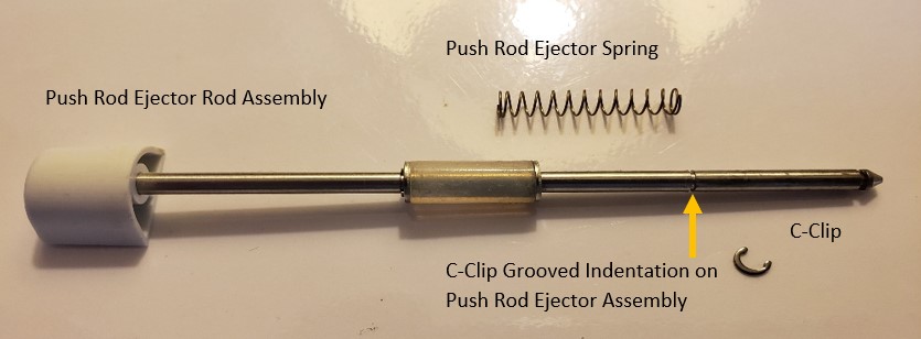
    Examine the Rainin push rod ejector assembly components with a special emphasis on the grooved indentation on the push rod.

    Note: The grooved indentation is the location where the c-clip will attach to during reassembly. The c-clip provides tension to the ejector spring, as well as keep the push rod ejector assembly in the pipette body.

    Disassembled push rod ejector assembly
    OPTIONAL: Counter Assembly Replacement Instructions

    Reassembly Process

    Step 9:

    With the needle-nosed pliers, gently grab and hold a c-clip as shown below.

    C-clip in needle nose pliers
    Step 10:

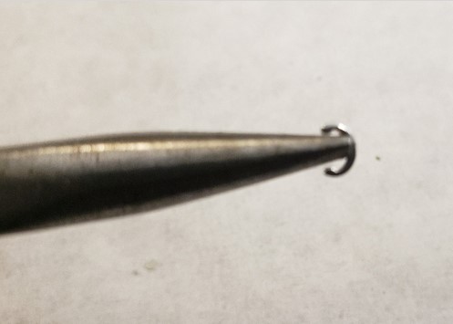
    Insert the c-clip into the grooved indentation on the c-clip installation tool, as shown below.

    C-clip being placed into insertion tool with needle nose pliers
    Step 11:

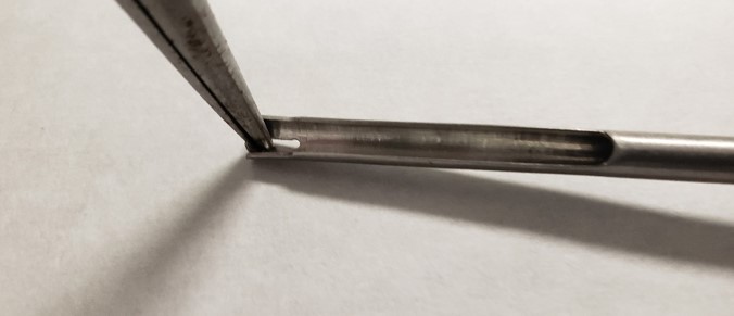
    Notice the c-clip inserted into the grooved indentation on the c-clip installation tool.

    C-clip installed into installation tool
    Step 12:

    Push and hold the ejector button. Gently slide the installation tool fully into the pointed end of push rod ejector rod assembly until the c-clip catches with the c-clip grooved indentation on the push rod ejector assembly. Shown in the picture on step 8.

    Step 13:

    Push the c-clip tool upward until you hear a slight click of the c-clip snapping back into place.

    C-clip and insertion tool placed inside of pipette body to place the c-clip
    Step 14: 

    Insert the piston assembly back into the shaft and screw the shaft coupling nut back onto the pipette body.

    Step 15:

    Reattach the tip ejector arm back onto the pipette body.

    Step 16:

    Check your work and correct as needed.

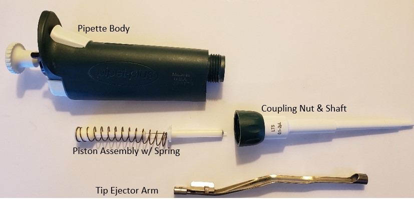
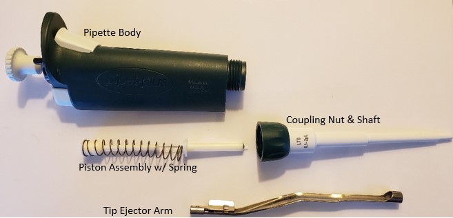
    Disassembled pipette, including piston assembly, coupling nut & shaft, and tip ejector arm

    Related Posts:

    Rainin Pipet-Lite, XLS, XLS+ Single Channel Pipettes: How to Perform Liquid End Assembly Preventive Maintenance

    Seal/O-Ring Vs. Lip Seal for Pipet-Lite, Pipet-Lite XLS, and E4-XLS Models

    Rainin Pipette Legend

    Pipet-Lite, XLS, XLS+ Calibration Tool, Item # RA CT-2

    Rainin Pipet-Lite, Pipet-Lite XLS: How to Tighten a Loose Volume Lock Top

    Disclaimer: Any action you take using the information on this website is strictly at your own risk. The information herein does not constitute professional advice and is general in nature. We make no warranty that this information will meet your requirements, be safe, accurate, or error-free. Pipette Supplies, Inc. is not responsible for any errors or omissions, any results obtained from the use of this information, or any loss or damage arising out of the use of this information. This site is for educational purposes only.
    Fair Use: Copyright Disclaimer under section 107 of the Copyright Act of 1976, allows for “fair use” for purposes such as comments, criticism, teaching, scholarship, news reporting, and research.
    Fair use is permitted by copyright statute that might otherwise be infringing.

  • Rainin EDP3-Plus Single Channel Pipette: Preventative Maintenance

    Learn how to perform crucial preventative maintenance on your Rainin EDP3-Plus pipette.

    In this post:

    Krytox Oil RA 6100-065
    Seals
    O-rings
    Shafts

    Rainin EDP3 Pipette

    Recommended Equipment for EDP3-Plus Preventive Maintenance:

    1. Laboratory gloves
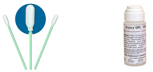
    2. Krytox GPL-105 Oil (Pipette Supplies: RA 6100-065)
    3. Foam Swabs for applying Krytox Oil & cleaning
    4. Kim Wipes & 70% IPA
    5. Replacement PM parts (as needed): Seal, O-Ring, Shaft
    6. Small-bladed flat head and Phillip screwdrivers
    Swabs and oil
    Step 1: 

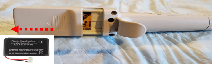
    Remove the battery from the EDP3-Plus to lock the motor in the home position and to prevent movement during preventive maintenance. This is accomplished by sliding the battery door upward and disconnecting the battery from the battery port.

    Removal of battery cover from the EDP3-Plus
    Step 2:

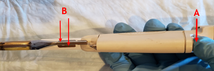
    Press down the tip ejector button (A), then press down on the tip ejector clips (B) to disengage the tip ejector from the pipette. Lay the tip ejector arm a side for reassembly later.

    Removing tip ejector from the EDP3-Plus
    Step 3:

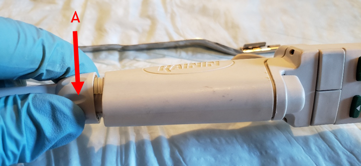
    Unscrew and fully remove the coupling nut (A) from the pipette

    CAUTION: There is an internal piston spring that may cause the seal and o-ring to shoot out of the shaft when removed. Be alert for parts that might pop off.

    Removing the coupling nut from the EDP3-Plus
    Step 4:  

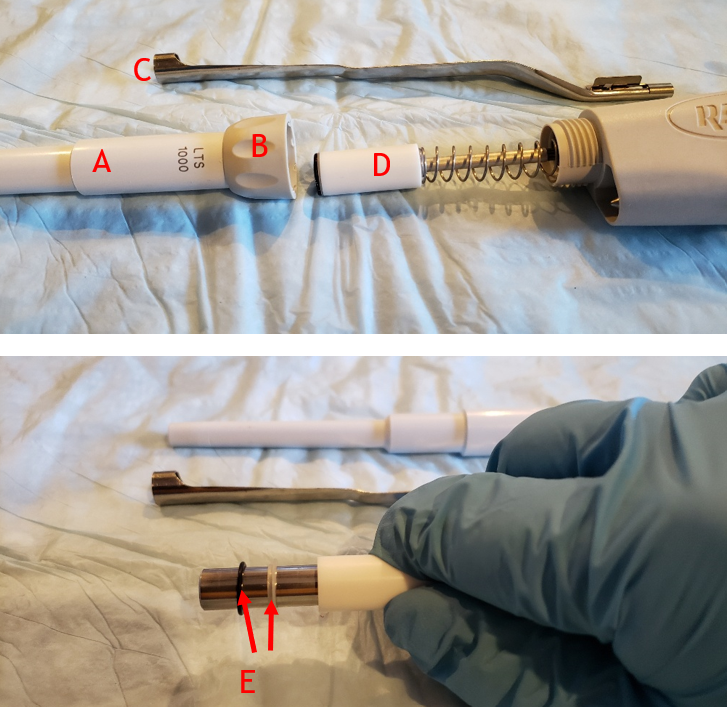
    Ensure that the following parts are accounted for after removing the shaft from the pipette

    A. White shaft
    B. Tan coupling nut
    C. Tip ejector arm
    D. Piston assembly w/ spring
    E. Seal and o-ring

    CAUTION: There is an internal piston spring that may cause the seal and o-ring to shoot out of the shaft when removed. Be alert for parts that might pop off.

    Disassembled EDP3-Plus with labeled parts. Seal and o-ring on piston.
    Step 5:

    With the seal and o-ring removed, clean/wipe the piston with a clean kim wipe to remove any lubricant, chemical splash, or debris, from the piston.

    IMPORTANT: Only wipe the piston once with the kim wipe and discard. If additional wiping is needed, use a fresh kim wipe for each additional wipe to prevent scratching the piston.

    Step 6

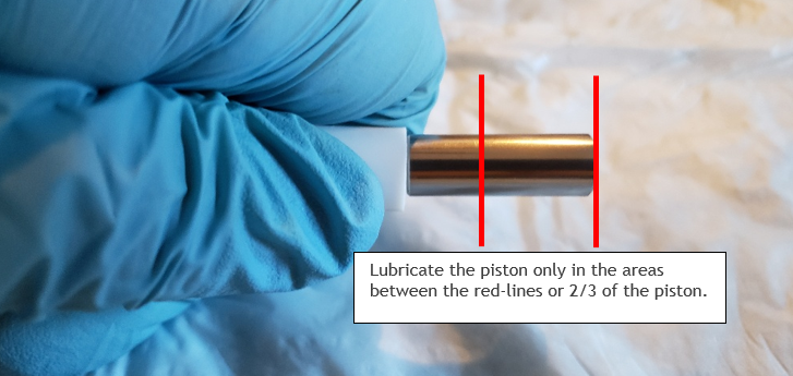
    Once the piston is fully cleaned, apply a minute amount of Krytox oil onto a foam swab. Lightly coat the piston with the Krytox oil in between the red lines, as shown to the left (only 2/3 of the piston).

    Area on piston to lubricate
    Step 7:

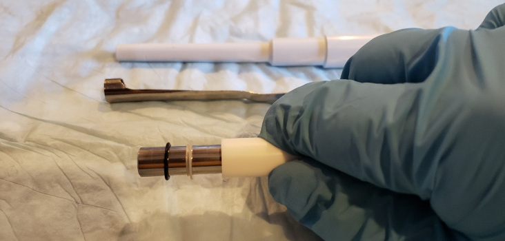
    Install a new seal on the piston followed by the black o-ring on the piston, as shown.

    NOTE: Pay attention to the orientation of the seal when installing onto the piston. Clean/replace the shaft as needed.

    Seal and o-ring on piston.
    Step 8 Reassembly:

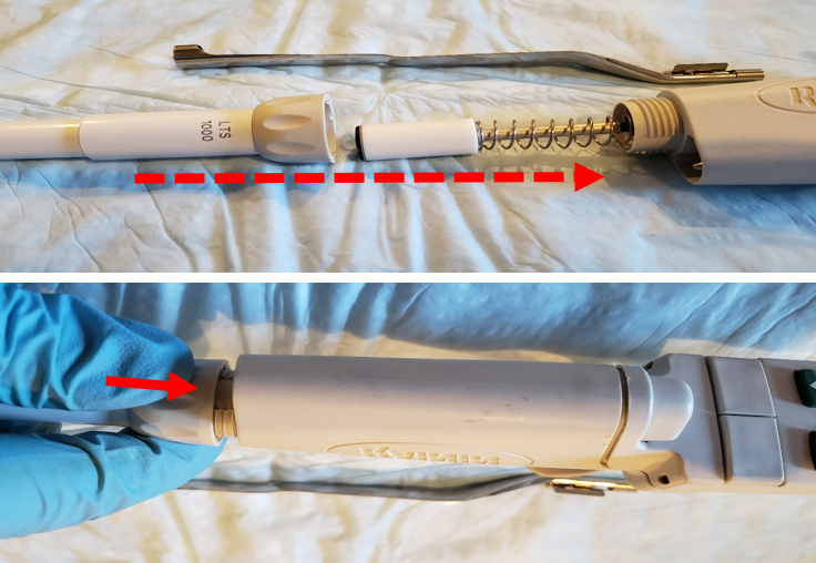
    Once the seal and o-ring are installed onto the piston, place the coupling nut onto the shaft, as shown.

    Step 9:

    Screw the shaft and shaft coupling nut onto the pipette body until it is fully threaded and secure.

    Reassembling the lower part on the EDP3-Plus
    Step 10:

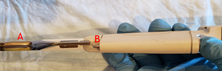
    Reattach the tip ejector arm (A) until it clicks back into place on the ejector rod (B).

    Step 11:

    Allow the pipette to equilibrate at least 60 minutes before verifying accuracy and precision. Recheck work as necessary.

    Reassembling the tip ejector on the EDP3-Plus

    Note: Adjusting the calibration on this pipette is performed only with proprietary software by RAININ. If the pipette is not accurate and/or precise after preventive maintenance, kindly recheck your work. If the seal, o-ring, shaft, and piston are in good condition, but the pipette is still out of tolerance, accuracy and/or precision wide, please contact the manufacturer as this is a discontinued pipette model.

    Related Posts:
    Rainin Pipet Lite XLS/XLS+ and Pipet-Lite Models: Counter Assembly Replacement
    Rainin Push Rod Ejector Assembly Replacement
    Rainin Pipet-Lite, XLS, XLS+ Single Channel Pipettes: How to Perform Liquid End Assembly Preventive Maintenance
    Seal/O-Ring Vs. Lip Seal for Pipet-Lite, Pipet-Lite XLS, and E4-XLS Models
    Pipet-Lite, XLS, XLS+ Calibration Tool, Item # RA CT-2

    Disclaimer: Any action you take using the information on this website is strictly at your own risk. The information herein does not constitute professional advice and is general in nature. We make no warranty that this information will meet your requirements, be safe, accurate, or error-free. Pipette Supplies, Inc. is not responsible for any errors or omissions, any results obtained from the use of this information, or any loss or damage arising out of the use of this information. This site is for educational purposes only.
    Fair Use: Copyright Disclaimer under section 107 of the Copyright Act of 1976, allows for “fair use” for purposes such as comments, criticism, teaching, scholarship, news reporting, and research.
    Fair use is permitted by copyright statute that might otherwise be infringing.
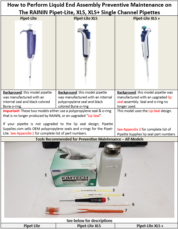
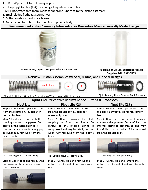
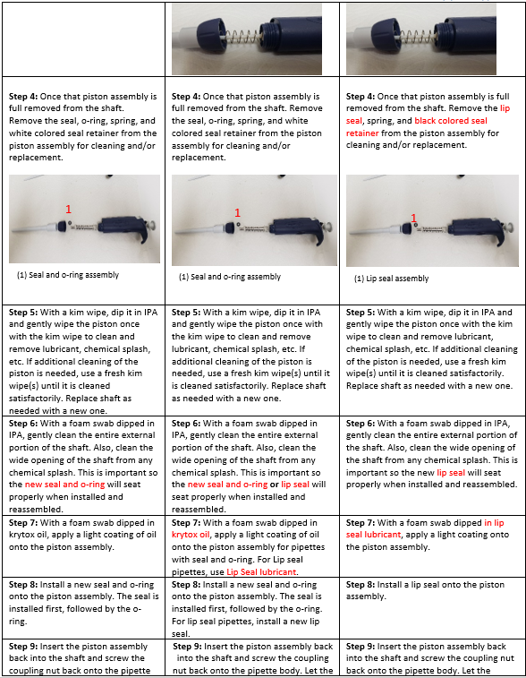
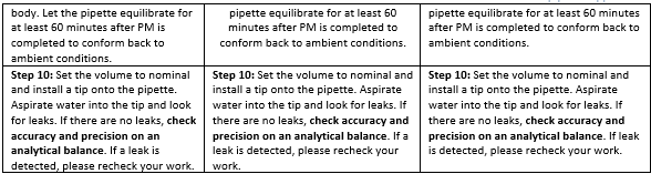
  • Rainin Pipet-Lite, XLS, XLS+ Single Channel Pipettes: How to Perform Liquid End Assembly Preventive Maintenance

    To perform Pipet-Lite preventative maintenance, you will need:
    Krytox Oil RA 6100-065
    Lip Seal Lubricant 2XLSGR55

    Instruction chart to perform preventative maintenance for the Pipet-Lite
    Recommended tools for preventative maintenance of the Pipet-Lite. Step 1-3
    Step 4-9 for preventative maintenance of the Pipet-Lite
    Step 10 for preventative maintenance of the Pipet-Lite
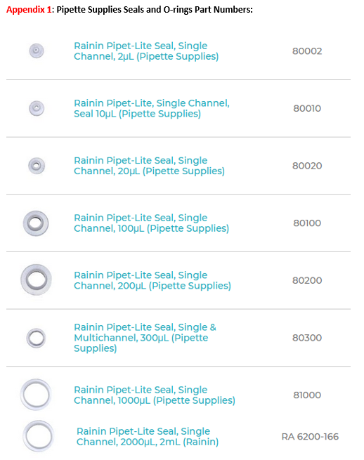
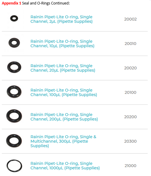
    PIpette Supplies - Rainin Pipet-Lite Seals

    Disclaimer: Any action you take using the information on this website is strictly at your own risk. The information herein does not constitute professional advice and is general in nature. We make no warranty that this information will meet your requirements, be safe, accurate, or error-free. Pipette Supplies, Inc. is not responsible for any errors or omissions, any results obtained from the use of this information, or any loss or damage arising out of the use of this information. This site is for educational purposes only.
    Fair Use: Copyright Disclaimer under section 107 of the Copyright Act of 1976, allows for “fair use” for purposes such as comments, criticism, teaching, scholarship, news reporting, and research.
    Fair use is permitted by copyright statute that might otherwise be infringing.
  • Rainin Pipet-Lite, Pipet-Lite XLS: How to Tighten a Loose Volume Lock Top

    Pipet-Lite / Pipet-Lite XLS Volume Lock Tightening Instructions:

    Replacement parts for the Pipet-Lite:
    Pipet-Lite & Pipet-Lite XLS Single Channel
    Pipet-Lite XLS Multichannel 
    Pipet-Lite XLS+ Multichannel

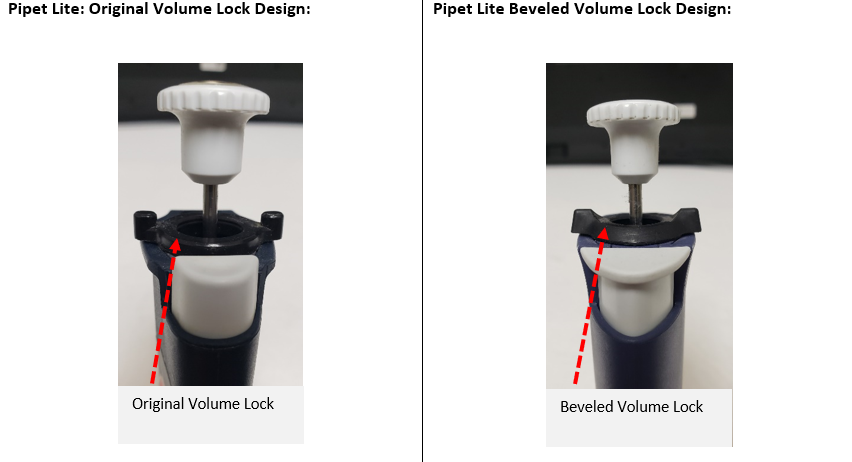
    Pipet-Lite original volume lock vs beveled volume lock
    DISASSEMBLY PROCESS

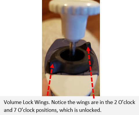
    Step 1: Gently unlock the volume lock so the volume lock wings are in the 2 o’clock and 7 o’clock position.

    Pipet-Lite volume lock wings in unlocked position

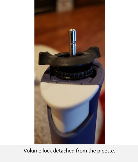
    Step 2: With a small-bladed tool, gently pry up one of the volume lock wings until the volume lock detaches. Once detached, remove the plunger button.

    Volume lock detached from the pipette

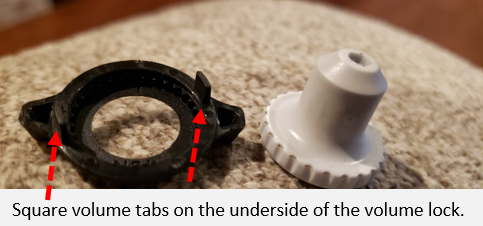
    Step 3:  Remove the volume lock top and plunger button and lay aside for reassembly later.

    Note: Please note the square tabs on the underside of the volume lock for reassembly later.

    Tabs on the underside

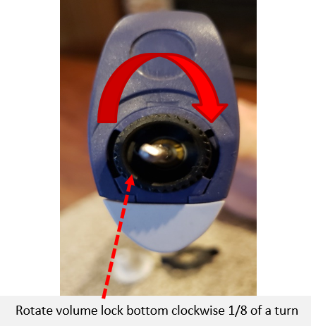
    Step 4:  Rotate the black colored volume lock base NO MORE THAN 1/8 of a turn clockwise to tighten a loose volume lock.

    Note:

    1. Rotate the volume lock base clockwise to tighten the volume lock.
    2. Rotate the volume lock base counter-clockwise to loosen a hard-to-turn or tight volume lock.
    Rotate the bottom clockwise 1/8th of a turn
    REASSEMBLY PROCESS

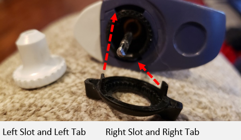
    Step 5: Place one of the square tabs on the underside of the volume lock into the left slot on the pipette body and the other tab into the right slot on the body.

    Pipette body slots and volume lock tabs

    Step 6:  Once aligned, press down, and snap the volume lock into place.

    Then rotate the volume lock to the 3 o’clock and 9 o’clock position and re-install plunger button.

    Note: If the Pipet-Lite volume lock is still loose, repeat the process until desired lock tension is achieved. Usually, 1/8 of a turn of the volume lock base is more than sufficient.

    Loose vs seated Pipet-Lite volume lock

    Disclaimer: Any action you take using the information on this website is strictly at your own risk. The information herein does not constitute professional advice and is general in nature. We make no warranty that this information will meet your requirements, be safe, accurate, or error-free. Pipette Supplies, Inc. is not responsible for any errors or omissions, any results obtained from the use of this information, or any loss or damage arising out of the use of this information. This site is for educational purposes only.
    Fair Use: Copyright Disclaimer under section 107 of the Copyright Act of 1976, allows for “fair use” for purposes such as comments, criticism, teaching, scholarship, news reporting, and research.
    Fair use is permitted by copyright statute that might otherwise be infringing.
  • Seal/O-Ring Vs. Lip Seal for Pipet-Lite, Pipet-Lite XLS, and E4-XLS Models

    In this post:
    Rainin Pipet-Lite, Pipet-Lite XLS, E4-XLS Seals
    Rainin Pipet-Lite, Pipet-Lite XLS, E4-XLS O-rings
    Rainin Pipet-Lite, Pipet-Lite XLS, E4-XLS Lip Seals
    Krytox Oil: RA 6100-0655
    Seal Lip Lubricant: 2XLSGR

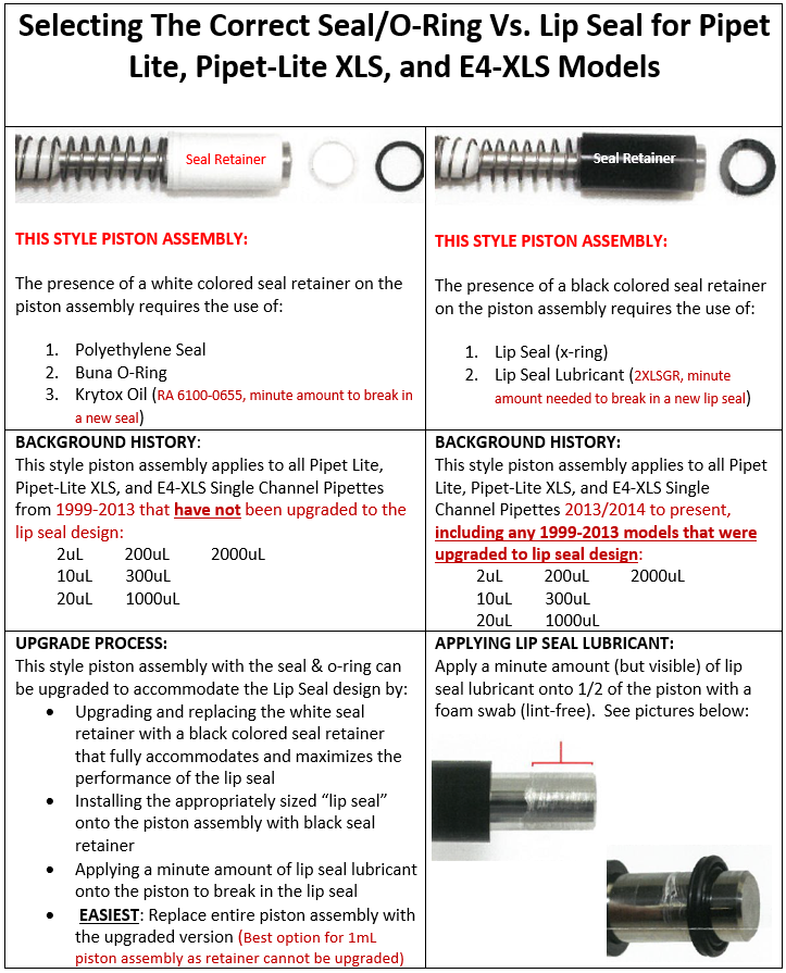
    Selecting the correct seal/o-ring vs lip seal for Pipet-Lite, Pipet-Lite XLS, and E4-XLS models

    Disclaimer: Any action you take using the information on this website is strictly at your own risk. The information herein does not constitute professional advice and is general in nature. We make no warranty that this information will meet your requirements, be safe, accurate, or error-free. Pipette Supplies, Inc. is not responsible for any errors or omissions, any results obtained from the use of this information, or any loss or damage arising out of the use of this information. This site is for educational purposes only.
    Fair Use: Copyright Disclaimer under section 107 of the Copyright Act of 1976, allows for “fair use” for purposes such as comments, criticism, teaching, scholarship, news reporting, and research.
    Fair use is permitted by copyright statute that might otherwise be infringing.

  • Rainin Pipette Legend

    What Rainin Pipettes do I have?

    This Rainin Pipette Legend aims to clarify the nomenclature of Rainin pipette codes and shorthand. Most codes are a mixture of a prefix letter, a hyphen, the max volume in microliters, and occasionally a suffix letter.
    Pipette Full NameShaft TypeRainin Code
    (Part# Prefix/Suffix)
    Example of
    SC 1000μl
    or MC 1200μl, etc
    E4-XLS / EDP4-XLS Single ChannelLTSE4-_XLSE4-1000XLS
    E4-XLS / EDP4-XLS Single ChannelTrad Univ
    SE4-_XLSSE4-1000XLS
    E4-XLS / EDP4-XLS MultichannelLTSE8/E12-_XLSE8/E12-1200XLS
    E4-XLS / EDP4-XLS Adjust Spacing MC – ASMLTSEA6/EA8-_XLSEA6/EA8-1200XLS
    E4-XLS+ / EDP4-XLS+ Single ChannelLTSE4-_XLS+E4-1000XLS+
    E4-XLS+ / EDP4-XLS+ Single ChannelTrad UnivSE4-_XLS+SE4-1000XLS+
    E4-XLS+ / EDP4-XLS+ MultichannelLTSE8/E12-_XLS+E8-1200XLS+ or E12-1200XLS+
    EDP1 Single ChannelLTSE1-E1-1000
    EDP1 Single ChannelTrad UnivSE1-SE1-1000
    EDP1 MultichannelLTSEP8/EP12/EP24/EP2X8-EP12-1200
    EDP2 Single Channel E2-E2-1000
    EDP3 / EDP3-Plus Single ChannelLTSE3-E3-1000
    EDP3 / EDP3-Plus Single ChannelTrad UnivSE3-SE3-1000
    EDP3 / EDP3-Plus MultichannelLTSE8/E12-E8/E12-1200
    EDP3 Adjustable Spacing MC – ASMLTSEA6/EA8-EA6/EA8-1200
    EDP3-Basic Single ChannelLTSE3B-E3B-1000
    EDP3-Basic Single ChannelTrad UnivSE3B-SE3B-1000
    EDP-Plus Single Channel EP-EP-1000
    EDP-Plus Multichannel EP-M8-EP-M8-10
    E-Man Hybrid Single ChannelLTSH-H-1000
    E-Man Hybrid Single ChannelTrad UnivSH-SH-1000
    Pipet-Lite Single ChannelLTSL-L-1000
    Pipet-Lite Single ChannelTrad UnivSL-SL-1000
    Pipet-Lite Fixed Volume Single ChannelLTSFL-FL-1000
    Pipet-Lite Single Channel XLSLTSL-_XLSL-1000XLS
    Pipet-Lite Single Channel XLSTrad UnivSL-_XLSSL-1000XLS
    Pipet-Lite Single Channel XLS+LTSL-_XLS+L-1000XLS+
    Pipet-Lite Single Channel XLS+Trad UnivSL-_XLS+SL-1000XLS+
    Pipet-Lite MultichannelLTSL8/L12-L8/L12-1200
    Pipet-Lite Fixed Volume MultichannelLTSFL8/FL12-FL8/FL12-1200
    Pipet-Lite Adjustable Spacing MC – ASMLTSLA6/LA8-LA6/LA8-1200
    Pipet-Lite Multichannel XLSLTSL8/L12-_XLSL8/L12-1200XLS
    Pipet-Lite XLS Adj Spacing MC – ASMLTSLA6/LA8-_XLSLA6/LA8-1200XLS
    Pipet-Lite Multichannel XLS+LTSL8/L12-_XLS+L8-300XLS+ or L12-300XLS+
    Pipet-Plus Single ChannelTrad UnivR-R-1000
    Pipet-Plus Single ChannelLTSRL-RL-1000
    Rainin ClassicTrad UnivPR-PR-1000
    Rainin Classic (Prior to 7/1/06)Trad UnivP-P-1000
    POS-D Positive Displacement Pipette MR-MR-1000
    DISP-X Bottle Dispenser Dispense-X DX-DX-10
    PIPET-X Pipet Controller PX-PX-NIMH
    Rainin Pipet-Lite E4 XLS Pipette(E4-20XLS, E4-100XLS, ...)
    Rainin Pipet-Lite E4 XLS (E4-20XLS, E4-100XLS, …)

    Disclaimer: Any action you take using the information on this website is strictly at your own risk. The information herein does not constitute professional advice and is general in nature. We make no warranty that this information will meet your requirements, be safe, accurate, or error-free. Pipette Supplies, Inc. is not responsible for any errors or omissions, any results obtained from the use of this information, or any loss or damage arising out of the use of this information. This site is for educational purposes only.
    Fair Use: Copyright Disclaimer under section 107 of the Copyright Act of 1976, allows for “fair use” for purposes such as comments, criticism, teaching, scholarship, news reporting, and research.
    Fair use is permitted by copyright statute that might otherwise be infringing.