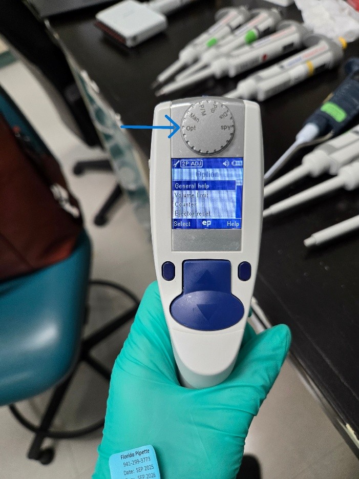
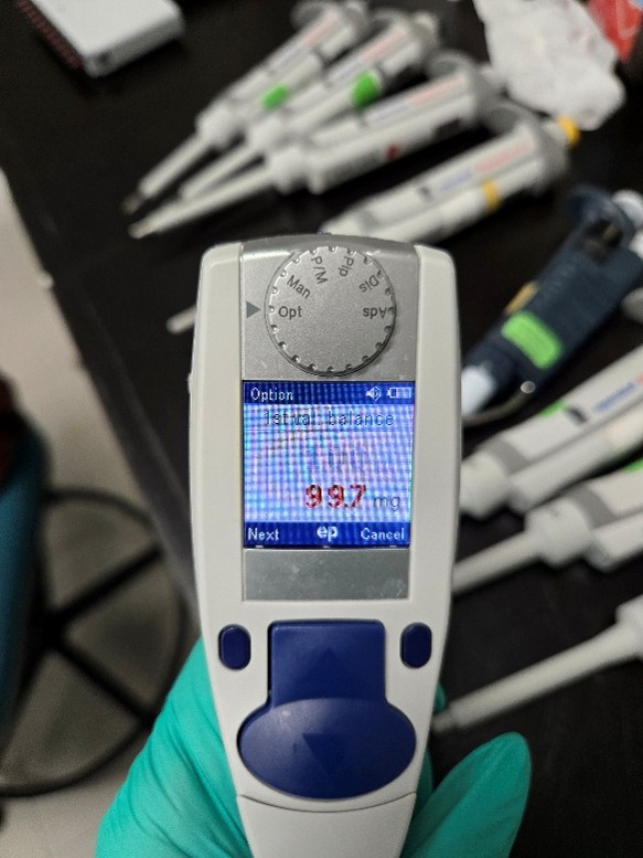
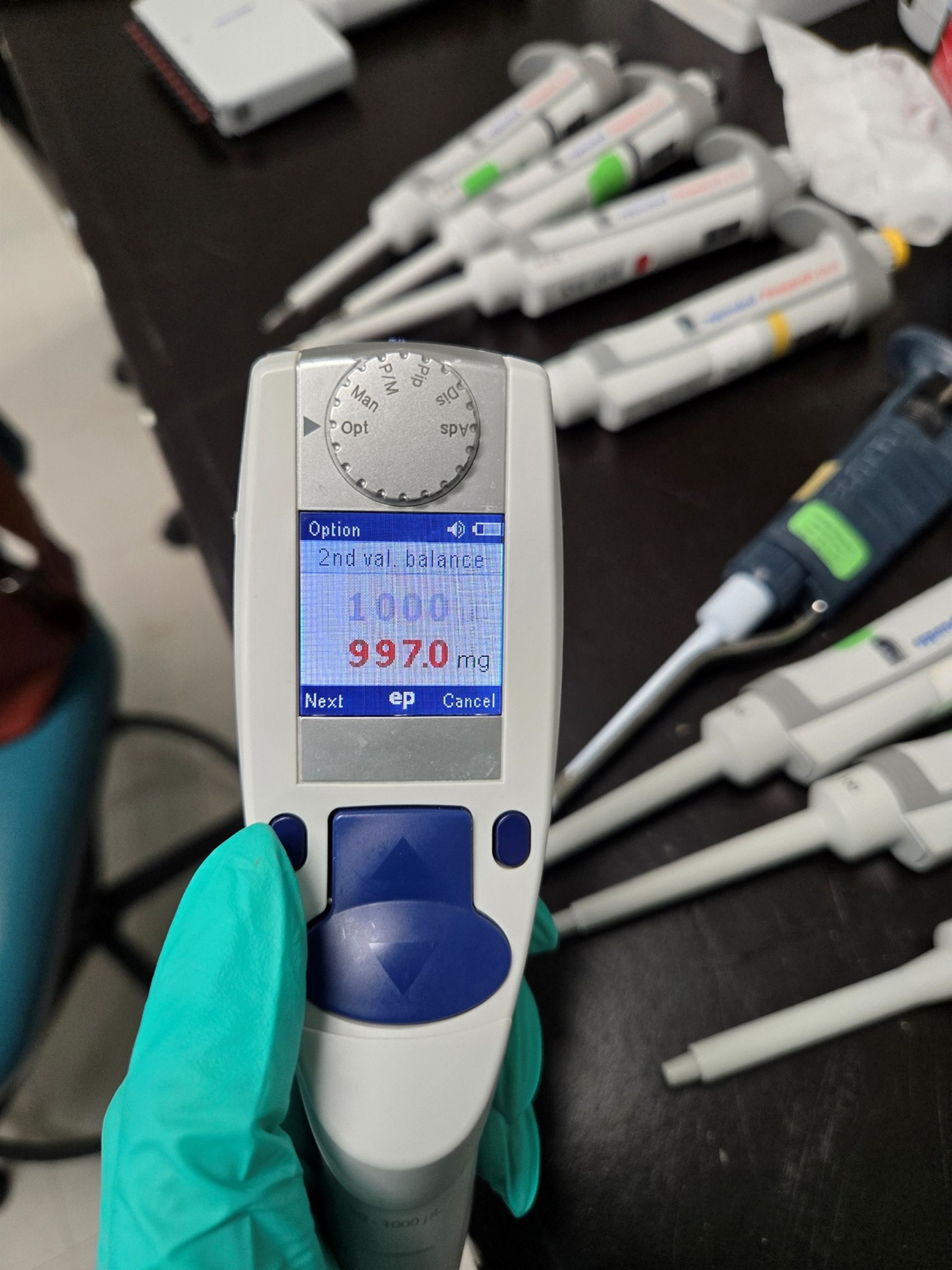
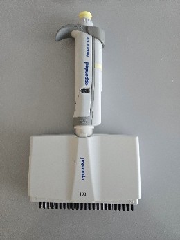
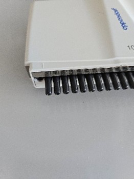
Toggle the Eppendorf Xplorer knob to ‘Opt’ (for Options)
Step 2:
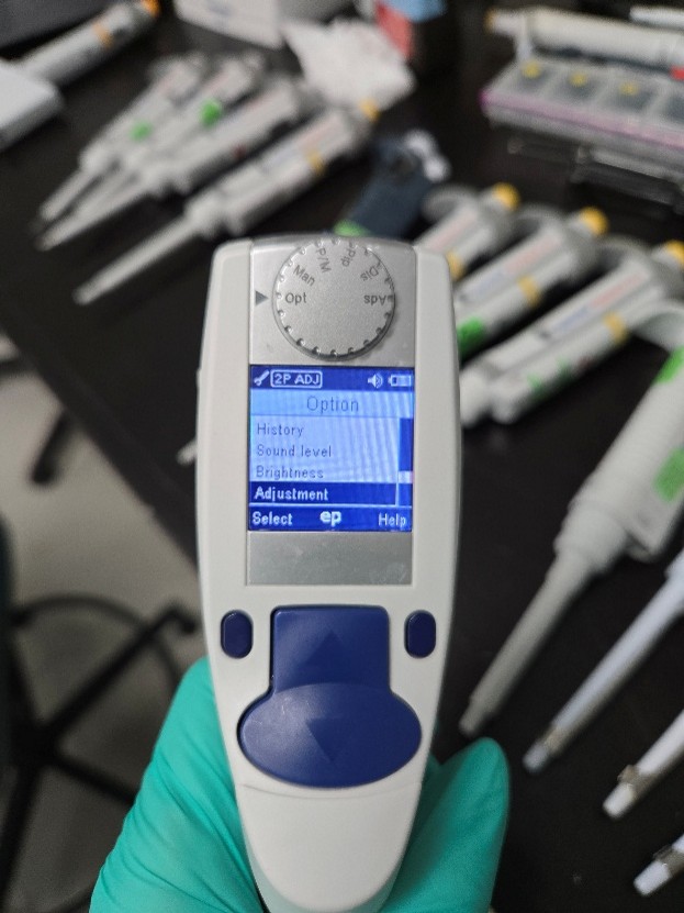
Use the up/down buttons to get to the ‘Adjustment’ option.
Step 3:
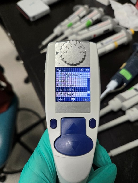
At this point you will have an option as to what type of adjustment you’d like to do. The options are 1-point, 2-point or 3-point. At this particular lab, they only needed testing at the high/low points so I selected 2-point adjustment.
Step 4:
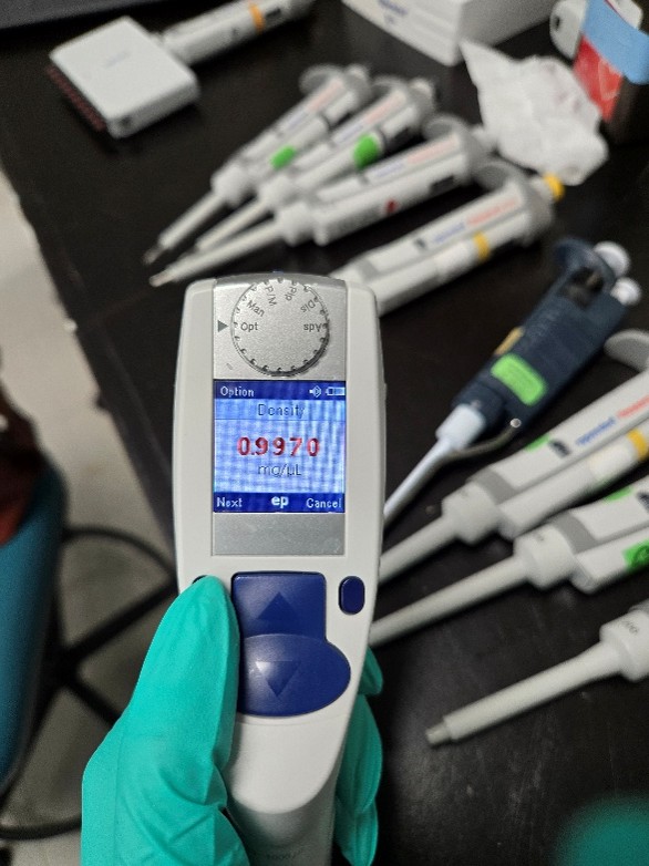
The first screen will ask you about the density of the water. You shouldn’t need to make any adjustments unless you are using something other than water. Click ‘Next’.
Step 5:
The next screen will show you what the volume should be and what it should be reading it mg. On a 2-point adjustment, the first volume it shows is the low reading. The volume will be in red. Click ‘Next’ and it will change the mg reading to red. Change the mg to what the pipette is currently reading at.
Example for a 1000ul: If your pipettes is reading at 89.0 at the low, set the mg reading to 89.0
Step 6:
The next option will be the high reading. Click ‘Next’ to get to the mg option and adjust to what the high volume is actually reading.
Step 7:
Once you adjust both readings it will give you the option to save the changes. Select ‘Yes’ and change the knob back to ‘Pip’. Let the pipette sit for a little while before testing, just like you would for manual pipettes.
Disclaimer: Any action you take using the information on this website is strictly at your own risk. The information herein does not constitute professional advice and is general in nature. We make no warranty that this information will meet your requirements, be safe, accurate, or error-free. Pipette Supplies, Inc. is not responsible for any errors or omissions, any results obtained from the use of this information, or any loss or damage arising out of the use of this information. This site is for educational purposes only. Fair Use: Copyright Disclaimer under section 107 of the Copyright Act of 1976, allows for “fair use” for purposes such as comments, criticism, teaching, scholarship, news reporting, and research. Fair use is permitted by copyright statute that might otherwise be infringing.
The repair process for a Research Plus multichannel nose cone replacement requires great care, a high attention to detail, patience, and steady hands. Please dedicate a good work area with good lighting and space where small parts can be located should they pop out during disassembly. If you don’t maintain attention to detail, you may damage the pipette and lose parts. Please proceed at your own risk.
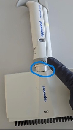
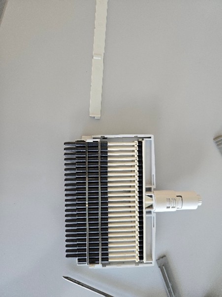
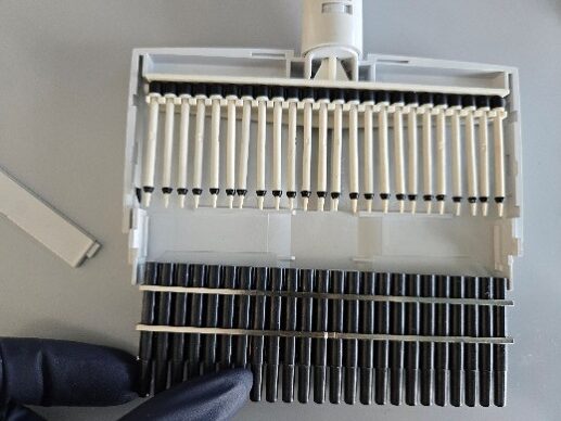
This is the 24-channel Eppendorf Research Plus. The first channel is broken off at the housing, so the entire channel needs to be replaced.
Step 1:
Begin by pulling this lever to the side to release the lower housing from the pipette body.
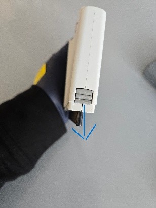
Open the housing by pulling the levers down to release the latch.
Step 2:
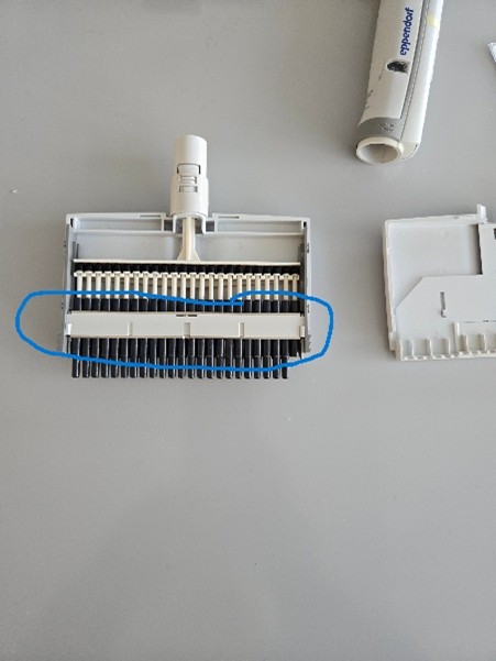
Once that is open, you’ll notice this plate that holds everything in place. Remove the plate (use a flathead screwdriver to help).
Step 3:
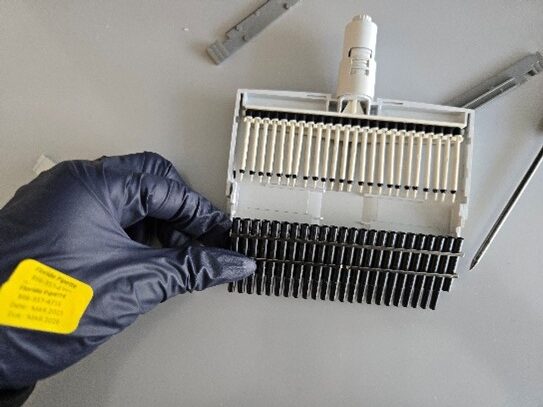
This entire lower unit is attached and will move together. The nose cones need to be removed entirely, which is done by sliding the unit down.
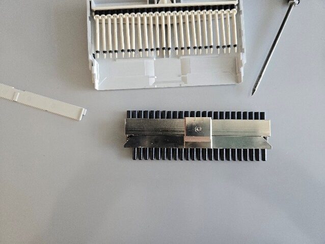
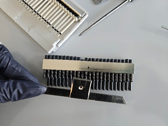
Once that is done, flip the entire unit over and you’ll see the screw that holds it all in place.
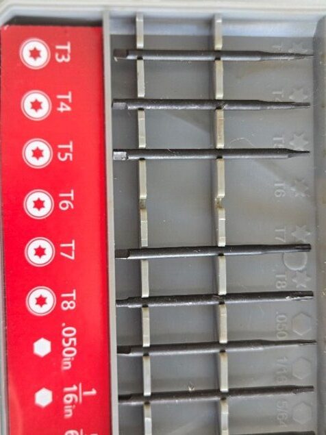
You will need a star screwdriver to remove the plate.
Step 4:
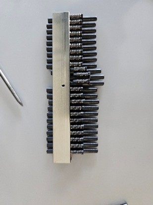
Once the plate is unscrewed you can remove it, but do so carefully because it is the only piece holding the nose cones in place. They will slide out easily. Be careful not to lose the springs that are attached to the nose cones.
NOTE: When you purchase a replacement nose cone, the spring is NOT included. You will need to use the one from the broken piece.
Step 5:
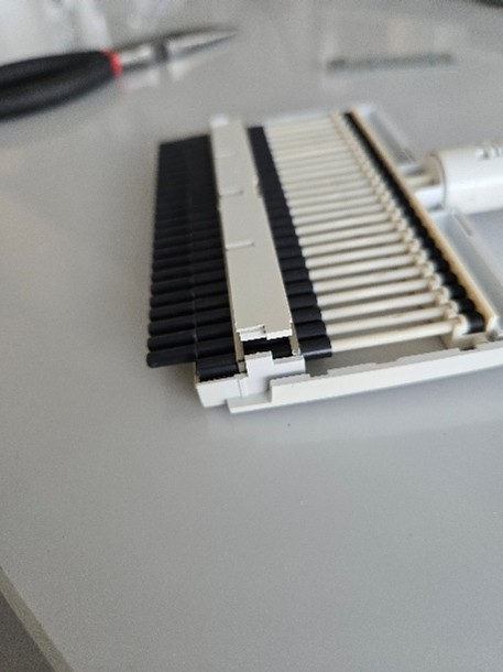
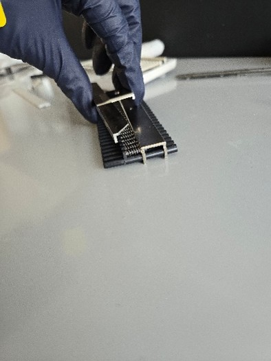
When you have replaced the nose cone, reattach the plate and screw it back in place. You’ll notice the bottom of the plate acts as a lip that holds the nose cones in place.
Step 6:
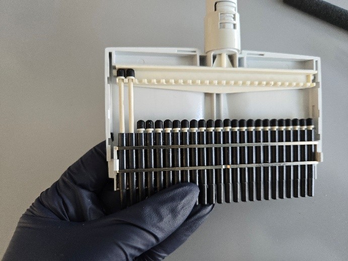
Once the plate is screwed back on, turn the assembly over so the screw is facing down. Carefully slide the nose cones back into the housing. All the nose cones must line up properly with the pistons or you will risk breaking a piston.
Another way to tackle this is to remove each piston and insert it into the nose cone first, once the nose cones are back in place, raise each piston individually and hook the back into the housing.
Step 7:
Reassemble the housing and reattach the housing to the body. It will snap back into place like a Research Plus single channel.
Disclaimer: Any action you take using the information on this website is strictly at your own risk. The information herein does not constitute professional advice and is general in nature. We make no warranty that this information will meet your requirements, be safe, accurate, or error-free. Pipette Supplies, Inc. is not responsible for any errors or omissions, any results obtained from the use of this information, or any loss or damage arising out of the use of this information. This site is for educational purposes only. Fair Use: Copyright Disclaimer under section 107 of the Copyright Act of 1976, allows for “fair use” for purposes such as comments, criticism, teaching, scholarship, news reporting, and research. Fair use is permitted by copyright statute that might otherwise be infringing.
The process of adjusting and troubleshooting leaks during calibration for the Eppendorf Reference 2 requires great care, a high attention to detail, patience, and steady hands. Please dedicate a good work area with good lighting and space where small parts can be located should they fly out during disassembly. Pipette damage and lost parts may occur if attention to detail is not maintained. Please proceed at your own risk.
Note: The 2.5µL, 10µL, & 20µL have seals that are built into the tip cone which would require the complete replacement of the lower assembly.
Recommend Supplies:
Gloves
Eppendorf Reference 2 adjustment tool: EP 3120633006
Note: Counter assembly issues are fairly common on the Reference 2 and can cause issues with making adjustments.
Step 1:
Set the pipette to 10% of the nominal volume and check its performance at this setting. If the pipette is operating outside of its specifications, record the value in microliters, as you will need it in Step 6. Refer to the most recent revision of the Reference 2 operating manual for your pipette’s specifications.
Step 2:
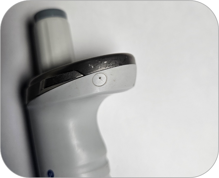
Locate the adjustment cap on the side of the pipette, near the volume catch.
Step 3:
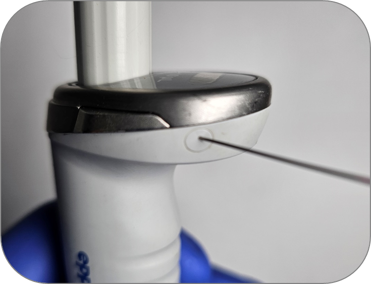
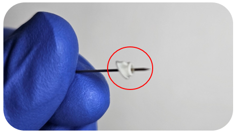
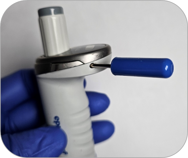
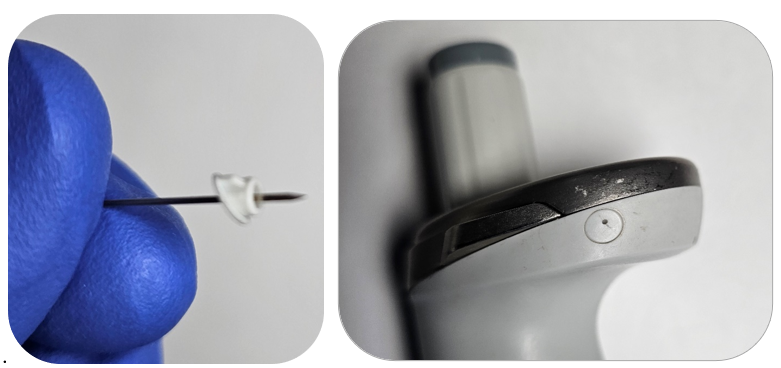
To remove the cap, insert a pin or push pin into the hole in the cap. In most cases, the pin will pass through the cap.
Note: Do not push the pin further in, as this could damage the counter.
Step 4:
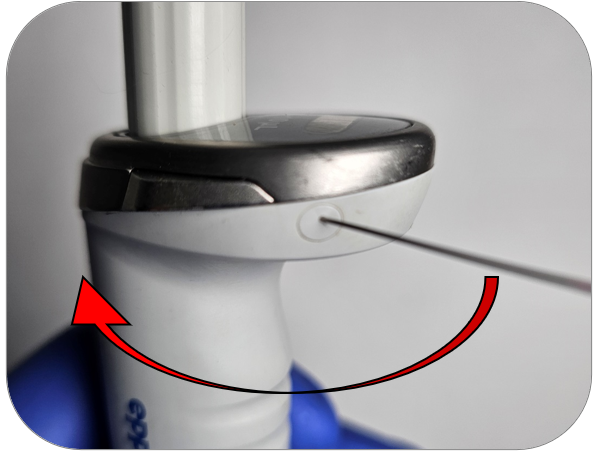
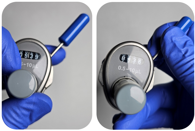
Once the pin is snug in the plastic cap, gently tilt the pin toward the volume catches. This will release the cap from the pipette body.
See the image below for reference.
Step 5:
Insert the Reference 2 adjustment tool into the hole where you removed the cap. Ensure the hex key aligns with the keyed hole.
Step 6:
Begin adjusting by holding the volume adjustment knob while turning the adjustment tool to the value you recorded in Step 1. Turning the tool clockwise decreases the volume, while turning it counterclockwise increases the volume.
Note: The volume adjustment knob tends to move during adjustments, so maintain a firm grip. If you notice binding or stripping in the adjustment mechanism, it is typically due to a counter issue. The adjustment mechanism should move with minimal effort. If a counter replacement is required, you can find the instructions at the following link:https://pipette.zenzen1.com/blog-eppendorf/eppendorf-reference-2-how-to-replace-the-volume-catch/
Step 7:
Recheck the pipette to confirm it is now operating within specification. If a leak is detected, check the tip holder and the seal/piston.
Step 8:
Once all adjustments are complete and the pipette is operating within manufacturer specifications at all volumes, reinstall the adjustment cap.
Note: The adjustment cap is keyed, so be sure to align the fin on the cap with the pipette body for a proper fit.
Disclaimer: Any action you take using the information on this website is strictly at your own risk. The information herein does not constitute professional advice and is general in nature. We make no warranty that this information will meet your requirements, be safe, accurate, or error-free. Pipette Supplies, Inc. is not responsible for any errors or omissions, any results obtained from the use of this information, or any loss or damage arising out of the use of this information. This site is for educational purposes only. Fair Use: Copyright Disclaimer under section 107 of the Copyright Act of 1976, allows for “fair use” for purposes such as comments, criticism, teaching, scholarship, news reporting, and research. Fair use is permitted by copyright statute that might otherwise be infringing.
The Xplorer has a clear ring that is injection molded into the pipette to attach the upper and lower parts during manufacturing. Unfortunately, there is no way to replace the ring once it is broken. Users will need to replace the entire pipette.
Disclaimer: Any action you take using the information on this website is strictly at your own risk. The information herein does not constitute professional advice and is general in nature. We make no warranty that this information will meet your requirements, be safe, accurate, or error-free. Pipette Supplies, Inc. is not responsible for any errors or omissions, any results obtained from the use of this information, or any loss or damage arising out of the use of this information. This site is for educational purposes only. Fair Use: Copyright Disclaimer under section 107 of the Copyright Act of 1976, allows for “fair use” for purposes such as comments, criticism, teaching, scholarship, news reporting, and research. Fair use is permitted by copyright statute that might otherwise be infringing.
The process of removing, replacing, and reinstalling the Research Plus sealing ring requires great care, a high attention to detail, patience, and steady hands. Please dedicate a good work area with good lighting and space where small parts can be located should they fly out during disassembly. Pipette damage and lost parts may occur if attention to detail is not maintained. Please proceed at your own risk.
Recommended Parts and Items
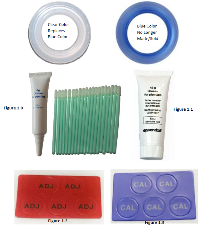
100uL-1000uL Research Plus Sealing Ring: EP 3120066047
Grease Options
8 Grams of Eppendorf Silicone Grease w/ Swabs: EP 0013022153 (Figure 1.0) or,
45 Grams Eppendorf Silicone Grease: EP 022348507 (Figure 1.1)
If adjustment is needed:
Sticker Options
Red colored adjustment sticker: EP 3120636005 (Figure 1.2) or,
Blue colored calibration sticker: EP 0012521848 (Figure 1.3)
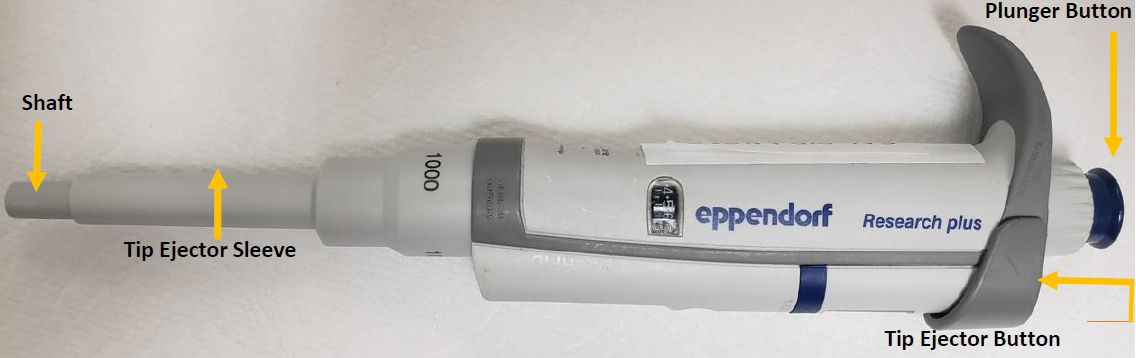
Identify and make yourself familiar with the main components that will need to be used to gain access to the internal sealing ring.
Step 2:
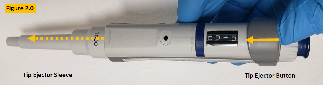
Press down and hold the tip ejector button to lower the tip ejector sleeve. Figure 2.0.
Step 3:
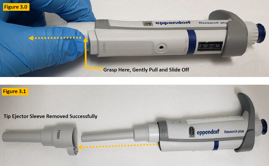
With the tip ejector button pressed, gently grasp the tip ejector sleeve, and gently slide and pull it off from the pipette body. Lay aside for reassembly. Figure 3.0.
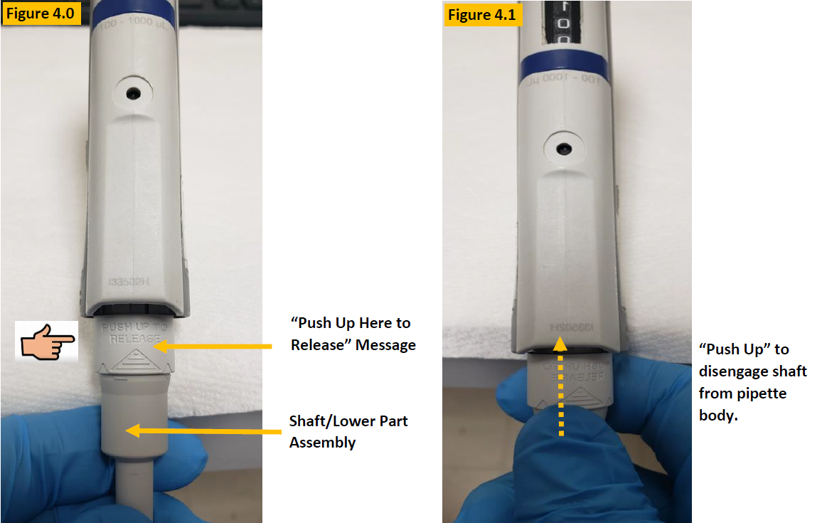
LOOK: Notice the engraved words on the shaft (lower part) “Push Up Here to Release” as shown in Figures 4.0 and 4. 1.
Step 4:
Push up gently but firmly to disengage the lower part assembly (shaft) from the pipette body. See Figure 4.1.
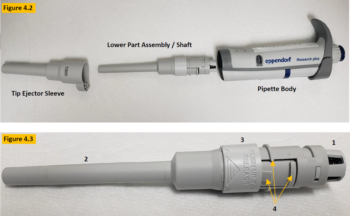
COMMENT: Figure 4.3 is an up close picture of the lower part assembly (Shaft). Familiarize yourself with the component names:
Piston Cap
Shaft
Push up/release.
Locking tabs/rings
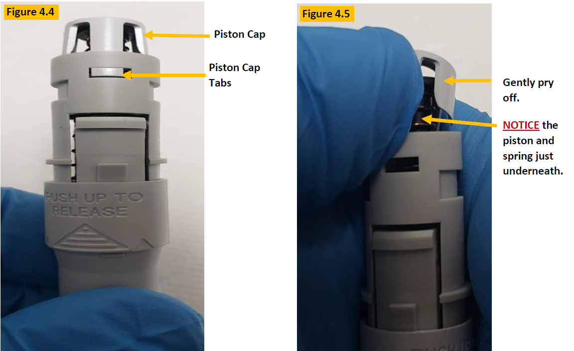
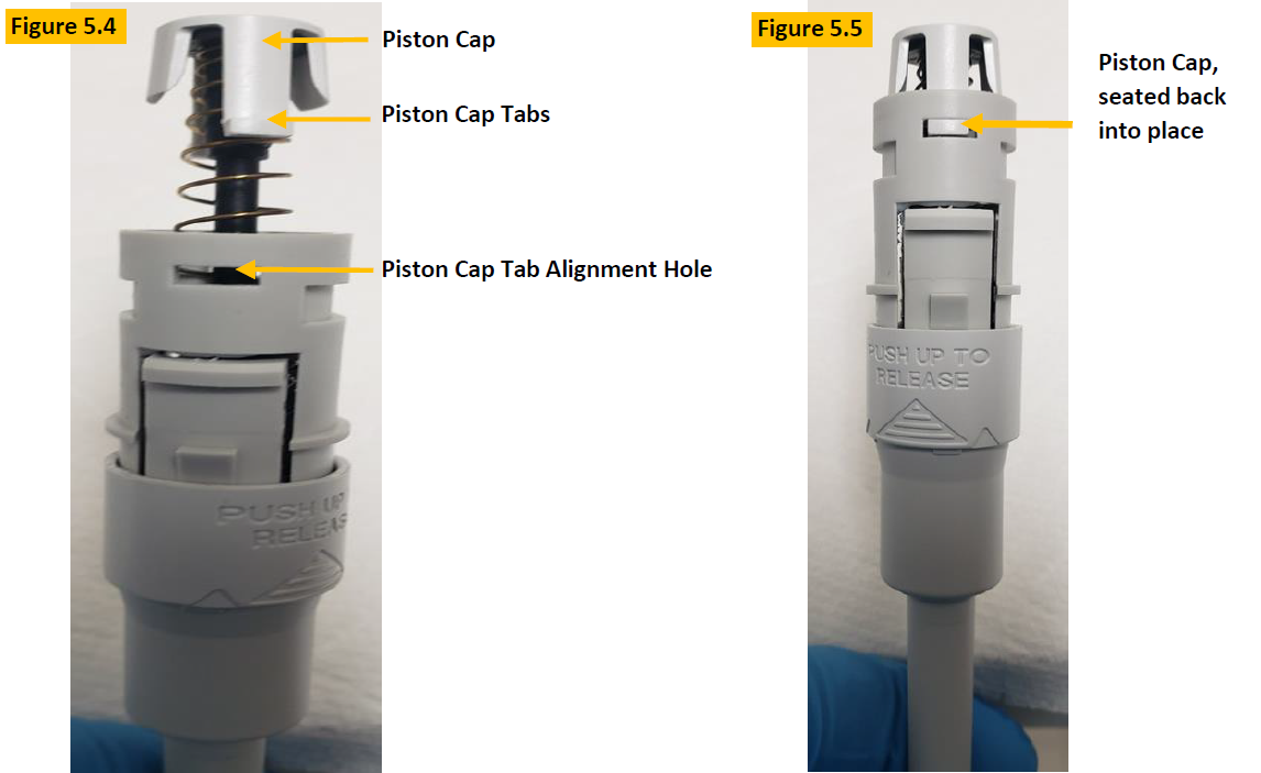
CAUTION: The piston cap holds the piston and piston spring in place, under tension. Use caution when removing the piston cap to prevent the spring and piston from flying out. Notice the piston cap tabs that hold it in place as shown in Figure 4.4.
Step 5:
Gently pry off the piston cap, as shown in Figure 4.5. Use your thumb to keep tension on the cap until you can grasp the piston and spring that are just below the piston cap. Remove the piston assembly from the shaft.
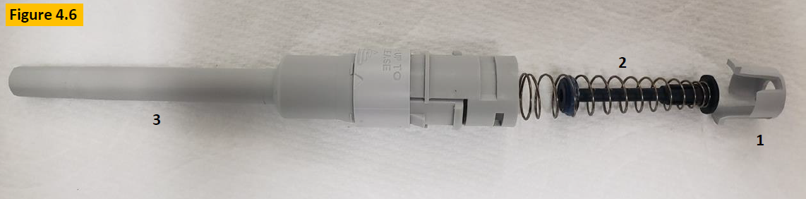
COMMENT: Observe the contents of the lower part after disassembly:
Piston Cap
Piston Assembly with spring & sealing ring
Shaft/Lower Part
Step 6:
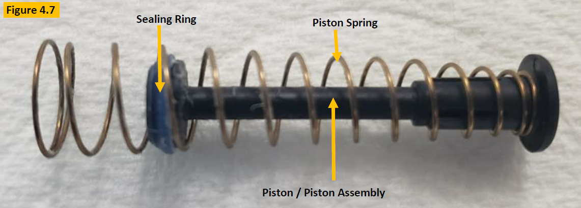
Inspect the piston, spring, sealing ring, and lubricant for damage, chemical splash, etc. as in Figure 4.7. Clean any component with a lint-free cloth (i.e. kim wipe) and 70% IPA as needed, and or replace if necessary.
Step 7:
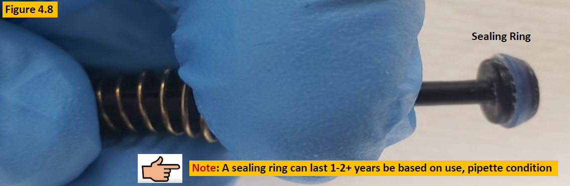
To clean the sealing ring and remove old lubricant, collapse the piston spring (Figure 4.8) so the sealing ring is unobstructed. Clean the sealing ring with 70% IPA and lint-free cloth. Inspect the sealing ring for cracks, splits, or wear. Replace as needed.
Step 8:
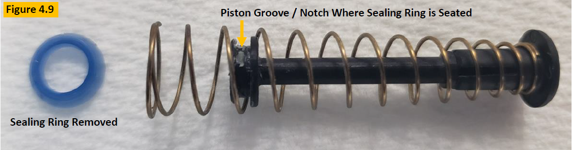
To replace the sealing ring, follow step 7 above, including cleaning removing the sealing ring from the piston with a small-bladed tool. See Figure 4.9.
Step 9:
Ensure the piston, piston spring, and piston groove are clean and free of lubricant.
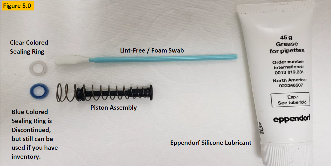
COMMENT: Per Figure 5.0, prepare your Eppendorf silicone grease, lint-free / foam swab, and Research Plus sealing ring for lubrication and installation.
Step 10:
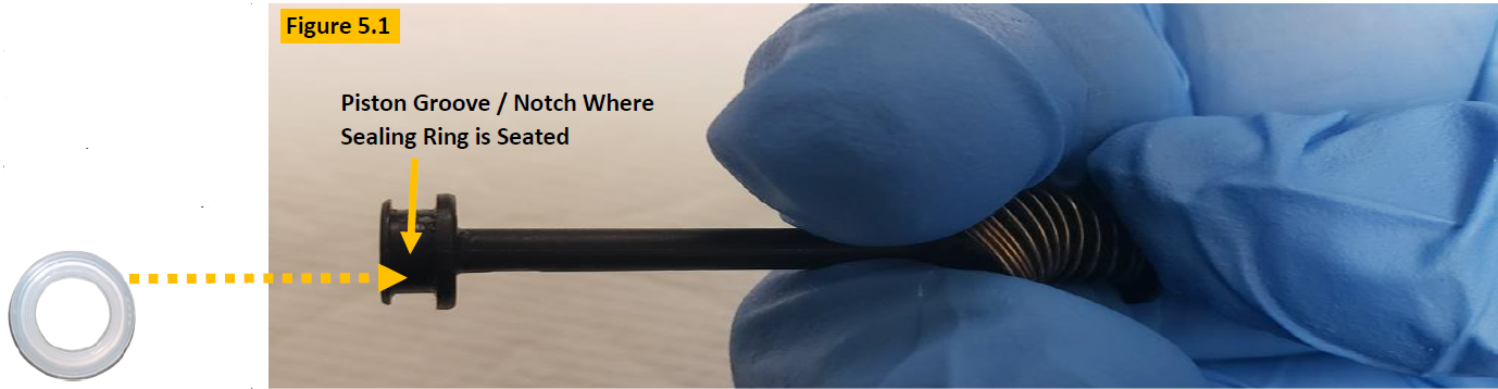
Collapse the piston spring as shown in Figure 5.1, to install the new sealing ring into the piston grooved / notched position until seated fully.
Step 11:
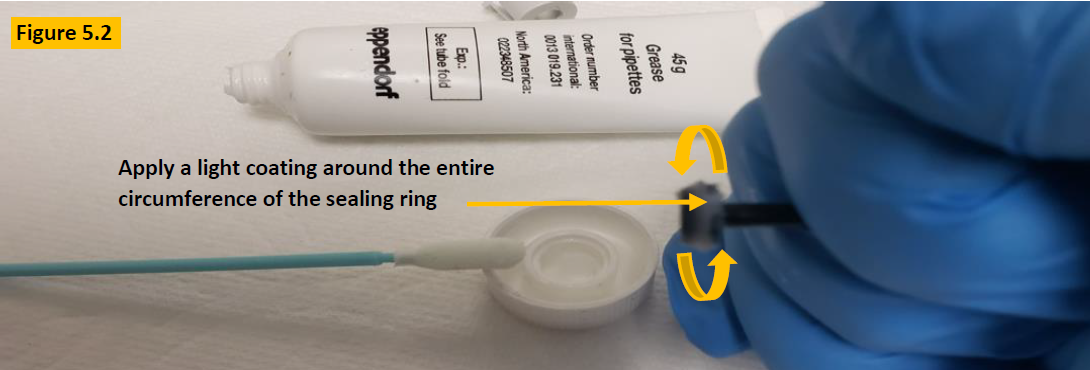
With the new sealing ring installed, apply a light coating (slightly visible to the eye) of Eppendorf silicone lubricant around the entire circumference of the sealing ring as shown in figure 5.2.
Step 12:
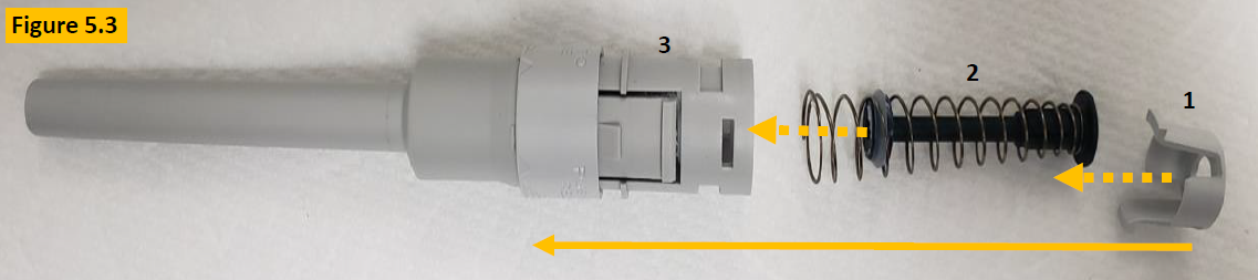
After installation and lubrication of the sealing ring, prep the lower part for reassembly as shown in Figure 5.3.
Step 13:
After placing the piston assembly back inside the shaft/lower part, place the piston cap over the end of the piston and press down until the tabs align and click in place (Figure 5.5).
Step 14:
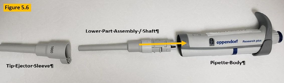
Insert the lower part assembly / shaft back into the pipette body opening and is fully attached. Figure 5.6.
Step 15:
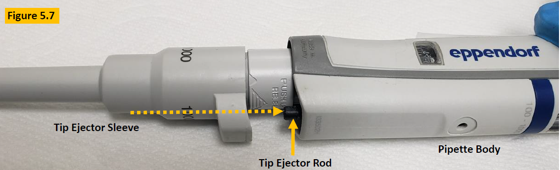
Press and hold the tip ejector button down. The black colored ejector rod will protrude from the body. Align the ejector sleeve with the ejector rod and click the tip ejector sleeve back onto the pipette. Figure 5.7.
Step 16:
Once the pipette is reassembled, allow it to equilibrate to ambient conditions for at least 60 minutes.
Step 17:
Perform a liquid leak test at nominal volume and then confirm pipette accuracy and precision, and desired results are obtained.
Adjustment Process – Only If Needed
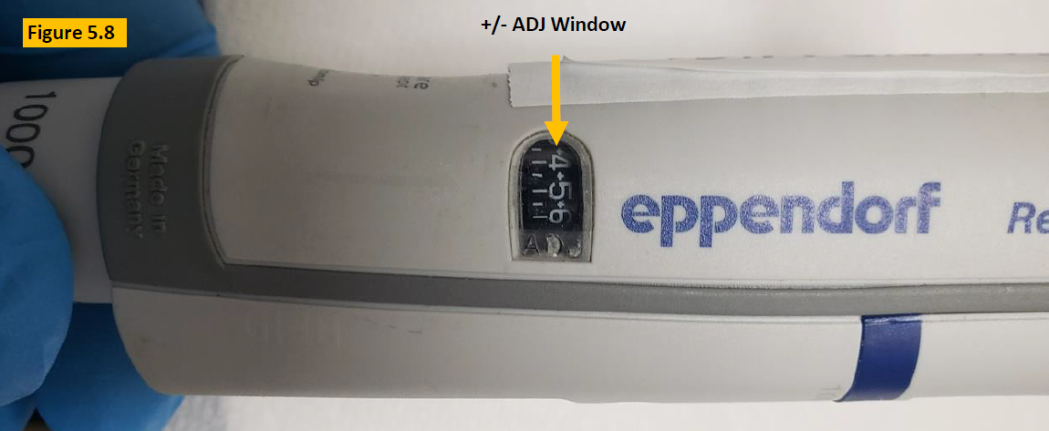
COMMENT: Figure 5.8, If the volume that is aspirated and dispensed is not desirable, then recheck your work as well as consider…
Is the ADJ window digits at “0”?
A possible calibration adjustment
Step 18:
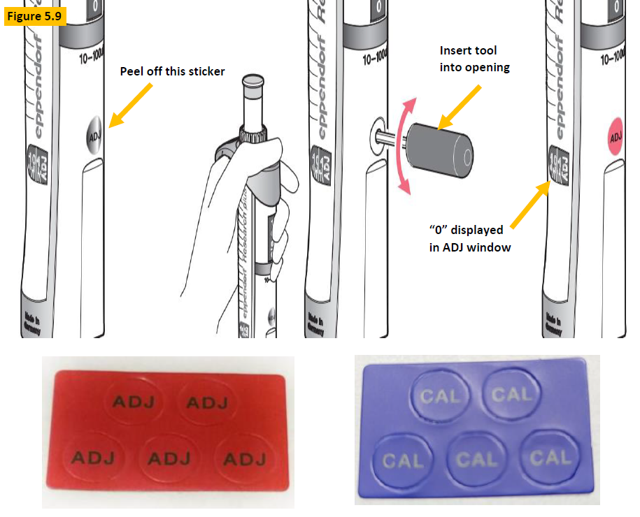
Figure 5.9. Peel off the red, blue, or gray colored ADJ or CAL sticker that covers the adjustment hole.
Step 19:
Press down and hold the tip ejector button, then insert the adjustment tool (EP 3120633006) into the opening and rotate until ADJ window aligns the “0” with the carat symbol.
Step 20:
With ADJ window set to “0”, recheck to see if desired volume is now achieved.
Step 21:
Affix replacement CAL or ADJ sticker over opening after tool is removed.
NOTE: If desired volume is not achieved, proceed to step 22.
Locate: Part number EP 3120639004/1, calibration adjustment tool as shown in Figure 6.0.
Step 22:
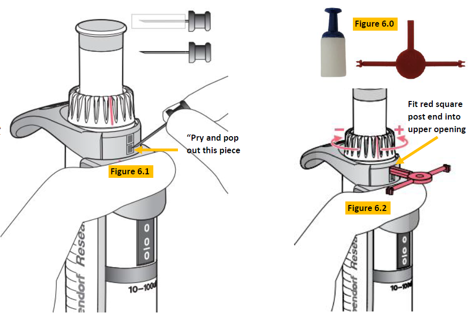
Press down and hold the tip ejector button. Insert the safety pin into the bottom square and pry/pop it out (Figure 6.1).
Step 23:
Insert the square post end of the red colored tool into the top gray square and push it downward so the red colored square post fits into the open slot (Figure 6.2). Adjust counter-clockwise to increase volume. Adjust clockwise to decrease volume.
Step 24:
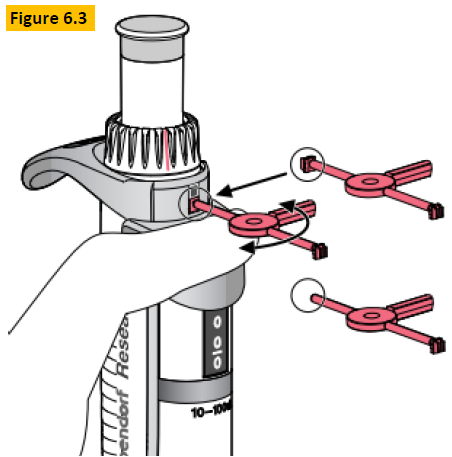
Once adjustment is completed, insert the replacement tab portion into the bottom opening and twist off until the tab is locked into position (Figure 6.3).
Step 25:
Check the pipette performance on a gravimetric balance to confirm desired results are obtained.
Disclaimer: Any action you take using the information on this website is strictly at your own risk. The information herein does not constitute professional advice and is general in nature. We make no warranty that this information will meet your requirements, be safe, accurate, or error-free. Pipette Supplies, Inc. is not responsible for any errors or omissions, any results obtained from the use of this information, or any loss or damage arising out of the use of this information. This site is for educational purposes only. Fair Use: Copyright Disclaimer under section 107 of the Copyright Act of 1976, allows for “fair use” for purposes such as comments, criticism, teaching, scholarship, news reporting, and research. Fair use is permitted by copyright statute that might otherwise be infringing.
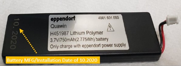
The Eppendorf Xplorer uses a 3.7V, 750mAh Lithium Polymer battery that provides many hours of reliable use and operation. In most cases, the battery will provide between 300-500 complete recharging cycles before replacement is needed. This equates to roughly 3-5 years with proper use. With this battery, the mfg./install date was 10.2020 meaning possible replacement could occur between October 2023-2025.
Of course, battery replacement depends on several factors including but not limited to:
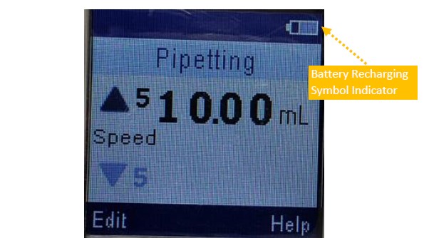
Will it recharge? What does the LCD battery logo show?
Are you using the manufacturer recommended wall power supply (WPS) and recharging stand? (strongly recommended)
Are you storing the pipette and battery in a cool, comfortable, and ambient-like conditions?
When not in use, is the battery being stored at 40%-50% of capacity to help prolong battery life?
Remember: DO NOT over charge or over discharge battery. Most pipettes have built in processes to regulate this from occurring, but it’s worth noting.
Xplorer Battery Replacement Instructions
Step 1:
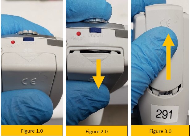
Gently pry open the battery door by lifting outward, as shown by the triangle logo on the battery door (figure 2.0).
Step 2:
Slide battery door upward (figure 3.0) and remove fully. Lay it aside.
Step 3:
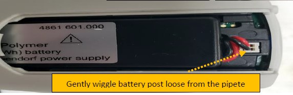
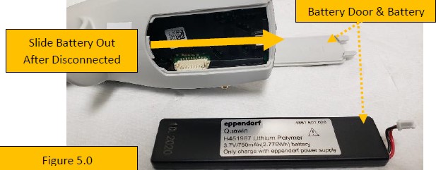
With the battery door removed, gently wiggle the white colored battery post until it unplugs from the pipette (figure 5.0).
Step 4:
After disconnecting the battery, slide it up and out of the battery compartment (figure 5.0).
Step 5:
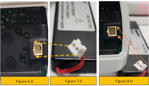
Notice the pin alignment of the battery port and the port itself (figures 6.0, 7.0, and 8.0). This is important for proper battery alignment and insertion.
Step 6:
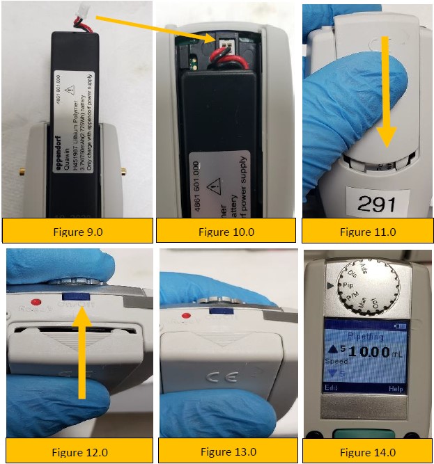
Slide the new battery into the pipette battery compartment (figure 9.0).
Step 7:
Align, connect, and plug-in the battery to the battery port (figures 6.0, 7.0, 8.0 and 10.0).
Step 8:
Slide the battery compartment door onto the pipette (figure 11.0).
Step 9:
As shown in figure 12.0, snap the battery door back into place with your thumb and index finger until it looks like figure 13.0.
Step 10:
Turn on the pipette and recharge the new battery until fully charged. Approximately 60-90 minutes.
Disclaimer: Any action you take using the information on this website is strictly at your own risk. The information herein does not constitute professional advice and is general in nature. We make no warranty that this information will meet your requirements, be safe, accurate, or error-free. Pipette Supplies, Inc. is not responsible for any errors or omissions, any results obtained from the use of this information, or any loss or damage arising out of the use of this information. This site is for educational purposes only. Fair Use: Copyright Disclaimer under section 107 of the Copyright Act of 1976, allows for “fair use” for purposes such as comments, criticism, teaching, scholarship, news reporting, and research. Fair use is permitted by copyright statute that might otherwise be infringing.
How to Replace the Volume Catch on an Eppendorf Reference 2 Pipette
The process of replacing the left and right-side volume catch, internal springs, and tab levers is a careful process that could damage the pipette if attention to detail is not maintained. Volume catch replacement requires a high level of patience and steady hands. Please dedicate a good work area with good lighting and space where small parts can be located should they pop/fly out during disassembly. Please proceed at your own risk.
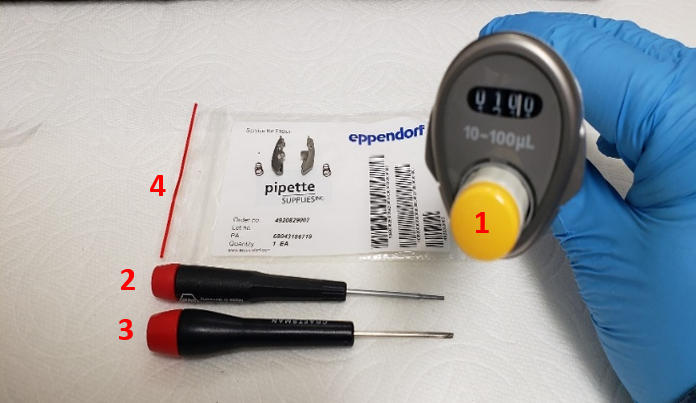
Equipment and Supplies Needed:
Eppendorf Reference 2 Pipette
A primary small-bladed tool such as a flat-head screwdriver
A secondary small-bladed tool such as a flat-head screwdriver (as a back-up if needed)
Volume Catch replacement parts, 2 pcs, Part # EP 4920829002
Step 1:
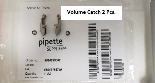
Verify and ensure that you have the PipetteSupplies.com Reference 2 Volume Catch replacement parts, 2 pcs, Part # EP 4920829002.
A set of two (2) volume tabs
A set of two (2) springs
Step 2:
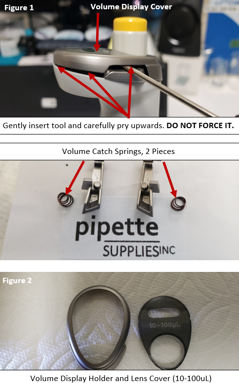
With the small-bladed tool, very carefully and very gently, insert the tool into the left side catch lever, as shown in figure 1.
Gently pry the volume display cover up. DO NOT force it.
Remove and re-insert your small-bladed tool in the right side catch lever and gently pry up. DO NOT force it.
CAUTION: When prying up the volume display cover, be aware that the volume catch springs may pop off and fly out of the pipette when the cover is removed.
Remove and re-insert your small-bladed tool into different areas just underneath the volume display cover and gently pry upward.
Keep repeating gently, as you would to pry off the lid on a can of paint, until the volume display cover comes off. As shown in figure 2.
Step 3:
With the display cover removed, locate and lay aside the following parts:
Volume Display Holder
Lens Cover
Left Volume Catch & Spring
Right Volume Catch & Spring
Step 4:
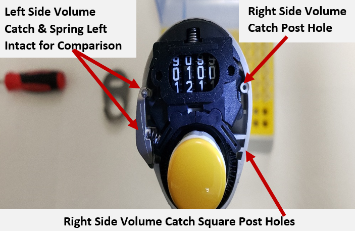
With the right-side volume catch & spring removed, notice the volume catch post hole that the volume catch will sit in when reassembled.
Secondly, notice the two (2) somewhat square post holes that the other end of the volume catch will sit on and spring location/position.
Double check all work. Ensure all parts are accounted for and/or new parts are available for installation before progressing to reassembly.
Observations of New Volume Catch & Preparations for Reassembly
Step 5:
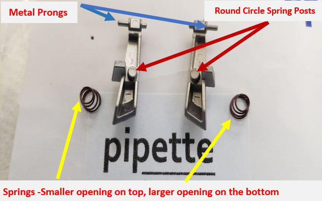
Inspect your new replacement volume catch and pay special attention to the following:
Springs – smaller end and larger end (if applicable)
Round circle spring post mounts on the volume catch
The metal prongs protruding from the top of the volume catch.
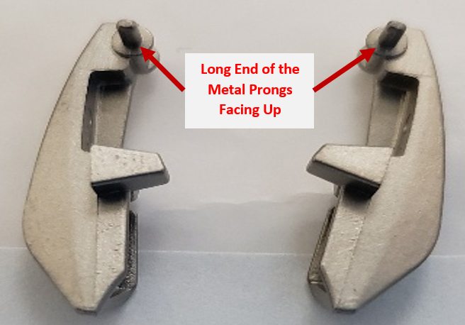
Observation 1:
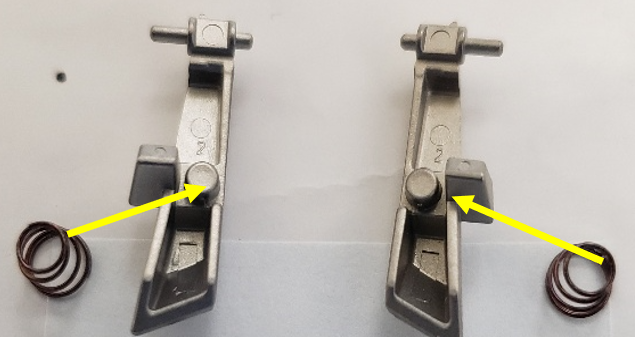
The volume catches pictured here are positioned in the orientation of how they would look if you were looking up from inside the counter assembly. Notice the metal prongs have the short end of the post facing down and the longer end of the metal post is facing up.
Observation 2:
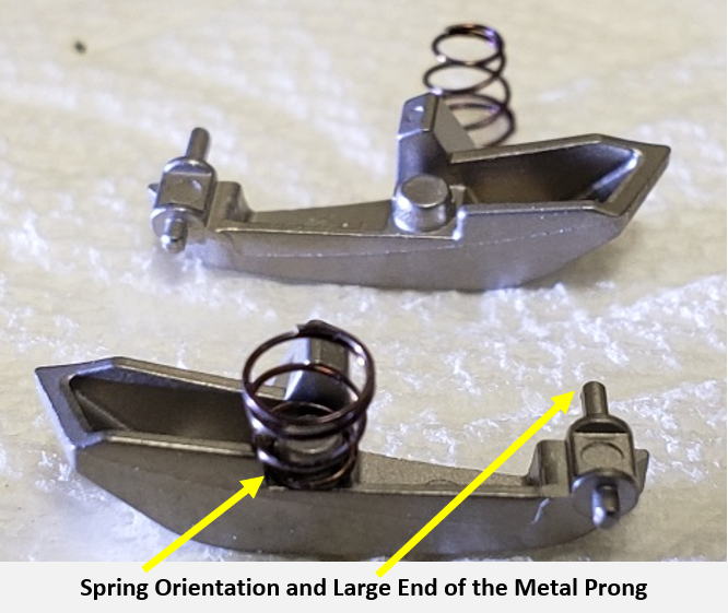
The volume catches pictured below are rotated with the underneath side facing up. Practice installing the small end of the spring onto the round circle spring posts. Note: Be aware during installation of the volume catch onto the pipette. The spring(s) my pop or fly off a few times until you masterthe installation process. Maintain keen eyes during this process.
Observation 3:
Close-up photo of the spring installed onto the volume catch. The other spring is positioned small side up for better visualization.
Notice the orientation of the longer end of the metal prong. This is the portion that is installed into the pipette body
The shorter prong is what is attached to the volume display cover.
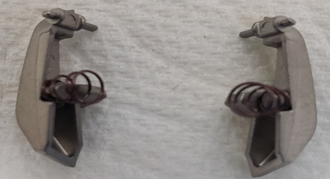
Observation 4:
Close-up photo of the springs installed onto the volume catch. The small end of the spring is installed first.
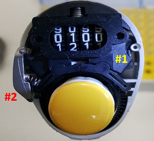
Observation 5:
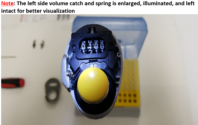
Enlarged photo of the right-side volume catch removed. (#1 below)
Left Side volume catch already installed for better visualization. (#2 below)
Volume Catch Installation and Re-Assembly
Step 6:
With the small end of the spring already inserted onto the volume catch:
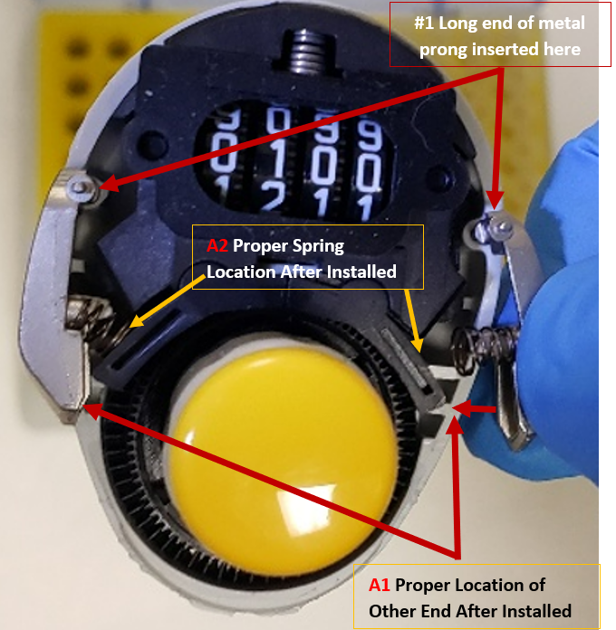
(1) Insert the long end of the metal prong into the round hole in the pipette body, as shown.
(2) Place the other end of the volume catch on top of the square holes, A1 until secure.
Note: When the lower end of the volume catch is properly installed, the spring will now be resting against “A2” and will be under tension. Do not bump or it will fly off and you will need to repeat the process.
This is the most tedious process and make take 3-5 times before mastered and the volume catch is properly installed.
Step 7:
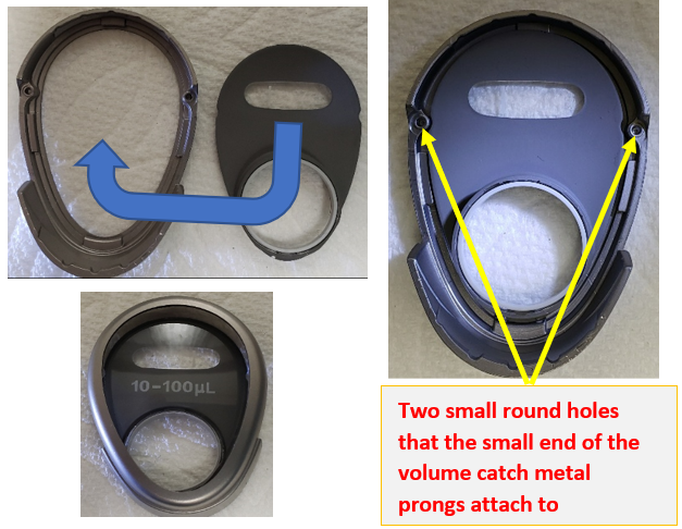
Insert the lens cover into the volume display holder.
Notice the two small round holes on the inside of the volume display holder. These are the posts that the short end of the metal prongs of the volume catch insert into when the volume display cover is installed back onto the pipette.
Step 8:
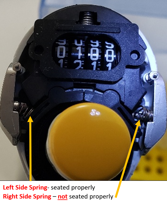
Double check that the volume catch and springs are still properly seated and in place, as shown here. If YES got to Step 9. If NO, re-install properly.
Step 9:
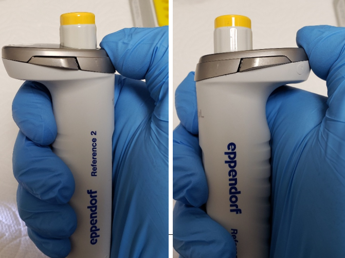
Once the volume catch and springs are properly positioned, install the volume display cover back onto the Reference 2 pipette until it snaps in place. Ensure there are no gaps, and that everything is snug.
Test the levers by pushing in on them and adjusting the volume. Recheck work as necessary. In some cases, calibration of the pipette may be required to ensure accuracy and precision is maintained.
Disclaimer: Any action you take using the information on this website is strictly at your own risk. The information herein does not constitute professional advice and is general in nature. We make no warranty that this information will meet your requirements, be safe, accurate, or error-free. Pipette Supplies, Inc. is not responsible for any errors or omissions, any results obtained from the use of this information, or any loss or damage arising out of the use of this information. This site is for educational purposes only. Fair Use: Copyright Disclaimer under section 107 of the Copyright Act of 1976, allows for “fair use” for purposes such as comments, criticism, teaching, scholarship, news reporting, and research. Fair use is permitted by copyright statute that might otherwise be infringing.
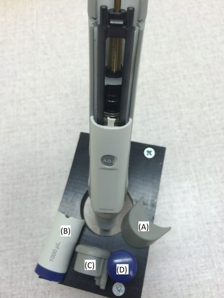
The ejector button (A) by pushing firmly upward to remove it from the pipette body.
The cover panel (B) by pushing in on the left side and then pushing up from the bottom colored-band portion.
The gray colored ring (C) and the colored plunger button cap (D) by firmly pulling upward.
Step 2
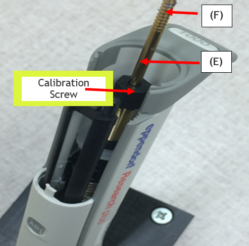
With a pair or rubber tipped pliers, grab and hold the brass-colored plunger rod at the location shown (E) to prevent it from rotating when the plunger button needs to be rotated and removed
With part (E) secure and not rotating, gently turn, rotate, and unthread the plunger button from the threaded portion of the brass-colored plunger rod (F).
Step 3
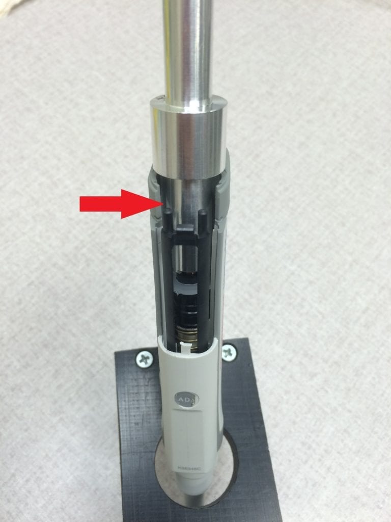
To calibrate, place the Research Plus Fixed adjustment tool (EP 3120802002) over the calibration screw. Make very subtle turns of counter-clockwise to increase & clockwise to reduce desired volume.
Remove the calibration adjustment tool and check the volume aspirated/dispensed on a balance. Replace all removed parts after desired calibration results are achieved.
Disclaimer: Any action you take using the information on this website is strictly at your own risk. The information herein does not constitute professional advice and is general in nature. We make no warranty that this information will meet your requirements, be safe, accurate, or error-free. Pipette Supplies, Inc. is not responsible for any errors or omissions, any results obtained from the use of this information, or any loss or damage arising out of the use of this information. This site is for educational purposes only. Fair Use: Copyright Disclaimer under section 107 of the Copyright Act of 1976, allows for “fair use” for purposes such as comments, criticism, teaching, scholarship, news reporting, and research. Fair use is permitted by copyright statute that might otherwise be infringing.
If you are receiving a “CO2 ERR” message on your Eppendorf Repeater M4, the potential root cause could be:
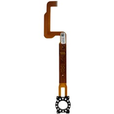
Combitip Sensor M4, part number: EP 4982811002, has become defective.
Either the white, round sensor(s) are not recognizing the combitip advanced syringes, or the bronze-colored internal sensor strip is damaged. Replacement sensors can be found here.
You may have mixed batches of Eppendorf Combitip-Plus and Combitip-Avanced syringes.
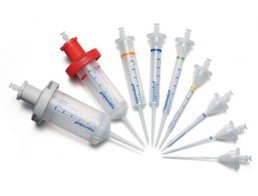
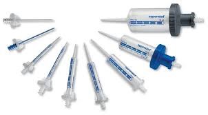
The M4 repeater is designed to be used with the Combitip-Advanced syringes. If an older style syringe, like the Combitip-Plus, is inserted onto the unit, the Combitip M4 sensor will not recognize it, thus triggering an CO2 ERR/CO3 ERR. The pictures below show the difference.
Eppendorf Combitip-Advanced:
Eppendorf Combitip-Plus (most look like this, with some minor differences in appearance):
The syringe ejector tabs are misaligned, thus preventing the syringe from being loaded and aligned properly with the combitip sensor.
The ejector tabs are charcoal colored/black and “C” shaped on the left and right side of the combitip sensor. It would be relatively easy to notice if the syringe is not loaded fully vertically and looks slanted or misaligned when loaded.
Of course, without seeing the unit, it is more difficult to 100% diagnose the exact cause of the Repeater M4 CO2 ERR. If the unit is confirmed under warranty, consider reaching out to Eppendorf for assistance.
Disclaimer: Any action you take using the information on this website is strictly at your own risk. The information herein does not constitute professional advice and is general in nature. We make no warranty that this information will meet your requirements, be safe, accurate, or error-free. Pipette Supplies, Inc. is not responsible for any errors or omissions, any results obtained from the use of this information, or any loss or damage arising out of the use of this information. This site is for educational purposes only. Fair Use: Copyright Disclaimer under section 107 of the Copyright Act of 1976, allows for “fair use” for purposes such as comments, criticism, teaching, scholarship, news reporting, and research. Fair use is permitted by copyright statute that might otherwise be infringing.
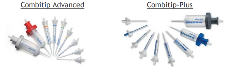
If your Repeater Plus is showing a C-4 Error, you may be using incompatible tips with the sensor in your pipette. The two types of Combitips are shown below, Combitip Advanced and Combitip-Plus.
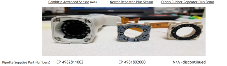
The older, rubber style sensor (see far right below), it not fully compatible with Eppendorf’s Advanced Combitip Syringes, especially if the rubber portion of the sensor is worn. This could be the cause of the Repeater Plus C-4 Error.
Recommendations:
To enable your pipette to use Combitip Advanced syringes, there are multiple recommendations to consider based on cost and time.
• Option 1: Order part number EP 4981802000 and install yourself. NOTE: There is always the possibility of other hidden internal damage. The pipette may need to be sent to an accredited service provider. It is harder to properly diagnosis hidden damage without seeing it first-hand.
• Option 3: Upgrade or trade-in your units for the Eppendorf Repeater M4
Disclaimer: Any action you take using the information on this website is strictly at your own risk. The information herein does not constitute professional advice and is general in nature. We make no warranty that this information will meet your requirements, be safe, accurate, or error-free. Pipette Supplies, Inc. is not responsible for any errors or omissions, any results obtained from the use of this information, or any loss or damage arising out of the use of this information. This site is for educational purposes only. Fair Use: Copyright Disclaimer under section 107 of the Copyright Act of 1976, allows for “fair use” for purposes such as comments, criticism, teaching, scholarship, news reporting, and research. Fair use is permitted by copyright statute that might otherwise be infringing.