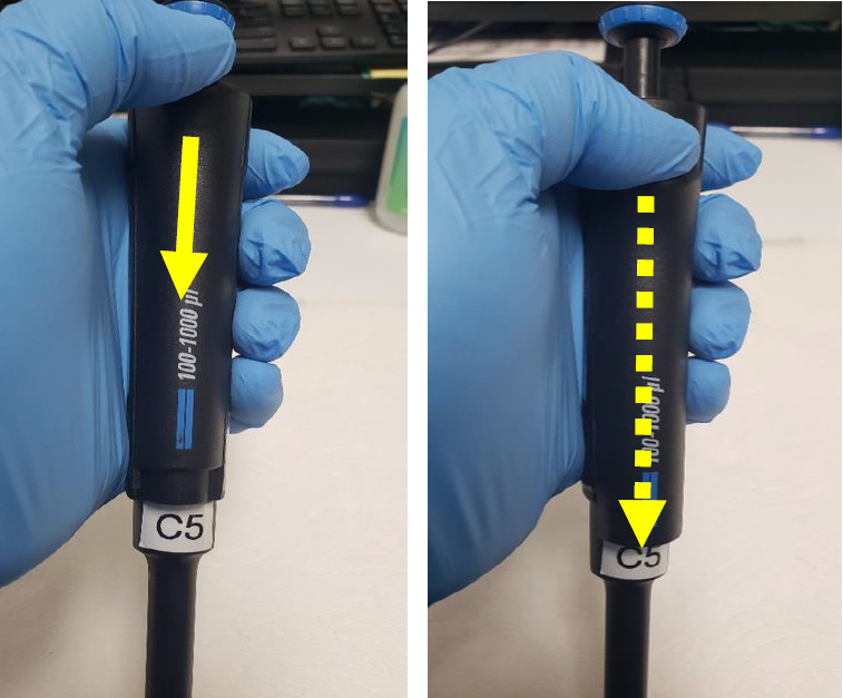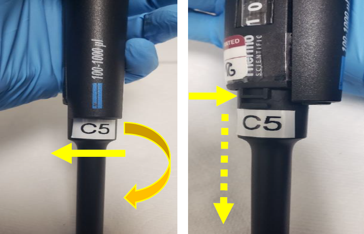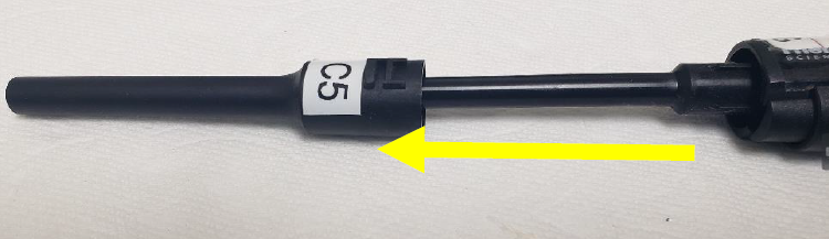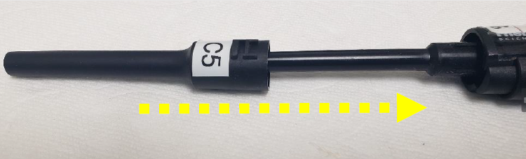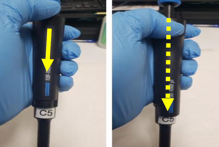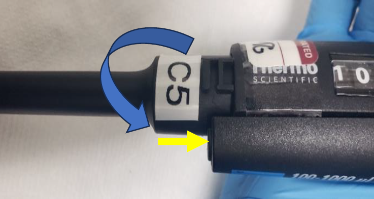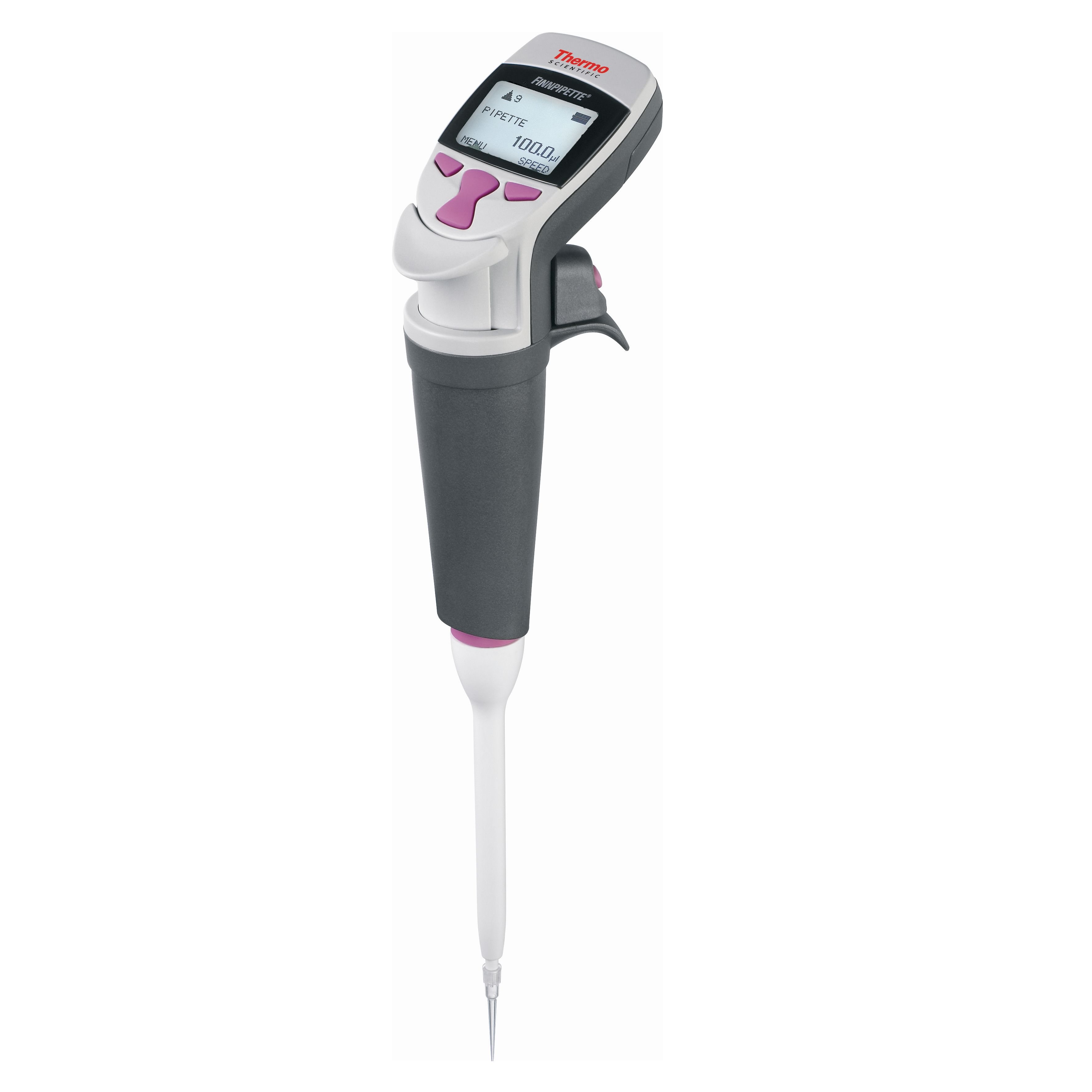
Category: Thermo Scientific / Finnpipette

  • ThermoFisher/Finnpipette – Window Replacement

    The process of removing, replacing, and reinstalling the windows for ThermoFisher / Finnpipette pipettes requires great care, a high attention to detail, patience, and steady hands. Please dedicate a good work area with good lighting and space where small parts can be located should they pop/fly out during disassembly. Pipette damage and lost parts may occur if attention to detail is not maintained. Please proceed at your own risk.

    These instructions are intended for the following pipette models: Finnpipette I, II, Digital, Focus, Novus, F-Series

    Replacement Parts:

    1. Digital/Finnpipette II Windows: Volume Specific
    2. Focus Windows: Volume Specific
    3. Novus Window/Lens: Universal

    Recommend Supplies:

    1. Pair of gloves
    2. Bottle of 70% IPA
    3. Cotton Swabs
    4. Flat-head screwdriver
    5. Phillips-head screwdriver(Novus)

    Digital/Finnpipette II Window Replacement Steps:

    Step 1:

    Start with the pipette on a flat surface, with the window/counter facing up. Insert a flat-head screwdriver or shim at the bottom of the window, where the Finnpipette name is printed. Ensure that the screwdriver or shim is positioned at the bottom of the window. Apply upward pressure to disengage the two tabs on either side of the window.
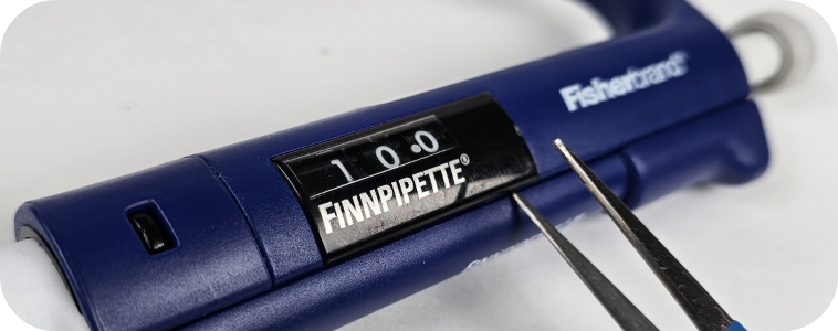
    Finnpipette window
    Step 2:

    It is a good idea to clean any debris from the inside edge of the window before reinstalling or replacing it. Use a cotton swab soaked in 70% isopropyl alcohol to clean these internal areas.
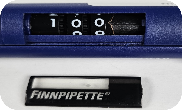
    Finnpipette window removal
    Step 3:

    To install the replacement window, line up the tab on the left side of the window with the side closest to the lower assembly. Once it is in place, push down on the window until the tab on the right side clicks into the other channel on the pipette body.

    Note: The window will not be flush with the pipette body when installed correctly (see picture below).

    Window not flush

    Focus Window Replacement Steps:

    Step 1:

    Using a flat-head screwdriver, pry up the soft grip cover on the finger hook side of the pipette. This grip is secured with a set of tabs on the top and bottom, along with a channel that holds the window/panel in place on both sides.
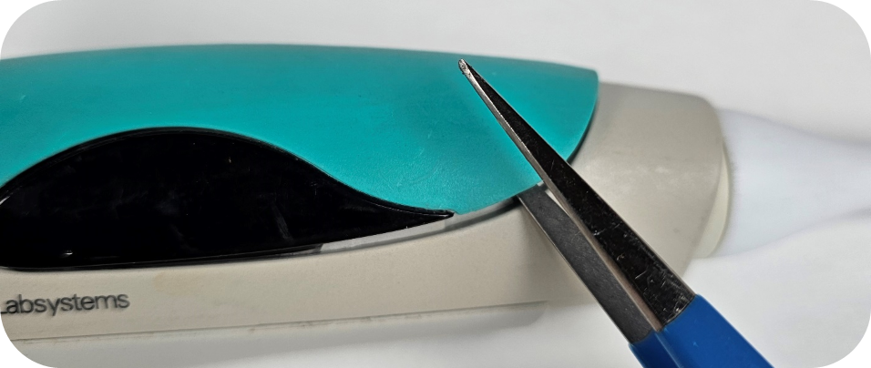
    Removing old window
    Step 2:

    Remove the old window and replace it with a new one. The window can be easily removed by inverting the pipette or lifting the window up.
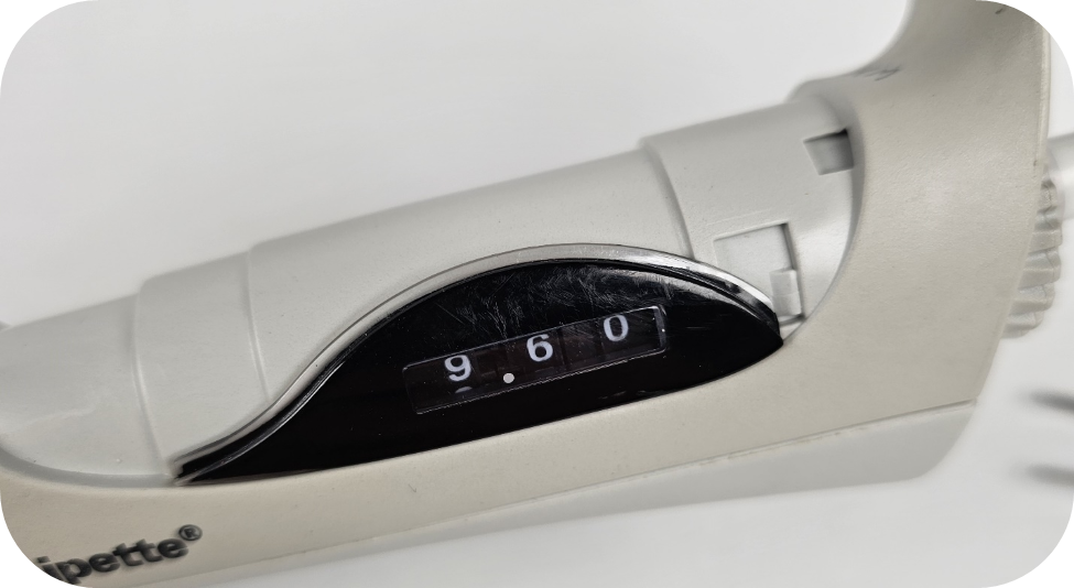
    window removed
    Step 3:

    Aligning the window/panel with the soft grip handle can be tricky. The picture below shows the channel on the soft grip that interacts with the top clear edge of the window (see picture above).
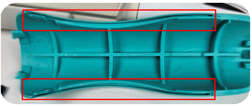
    Tabs and groves from soft grip
    Step 4:

    After installing the new window(s), you are ready to reassemble the pipette. Start near the finger hook by inserting the two tabs from the soft grip (shown in the picture above, far left) into their respective slots on the pipette body.
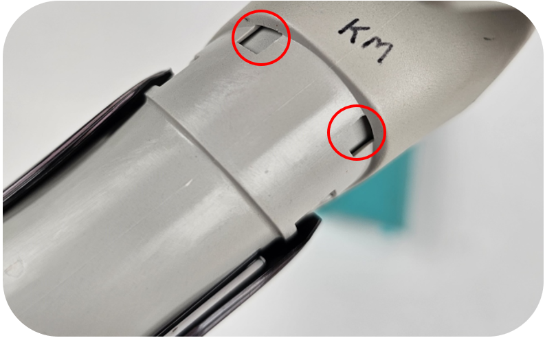
    tab slots

    Note: Picture below indicates where the tabs are located that interact with the two slots on the pipette body.
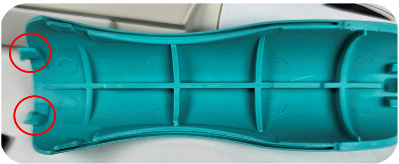
    inner tabs
    Step 5:

    It may take a few tries to align the windows with the channels outlined in Step 3. If you have trouble, you can use a flat-head screwdriver to make adjustments once the soft grip is flat.

    Note: The grip does not fit tightly against the pipette body. There may be some space or slightly flared corners on the soft grip after securing the window correctly.

    Novus Window Replacement Steps:

    Step 1:

    Remove the ejector button by pulling up on the ejector. This will expose two phillips-head screws.
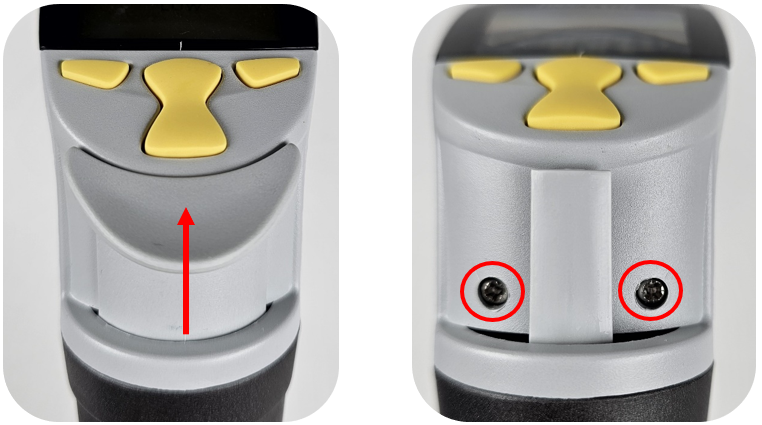
    Remove the ejector button
    Step 2:

    Remove both screws and set them aside.

    Step 3:

    Flip the pipette around and remove the battery door. Afterward, remove or disconnect the battery to prevent any potential damage while working on the unit. Additionally, remove the last two screws securing the frame in place.
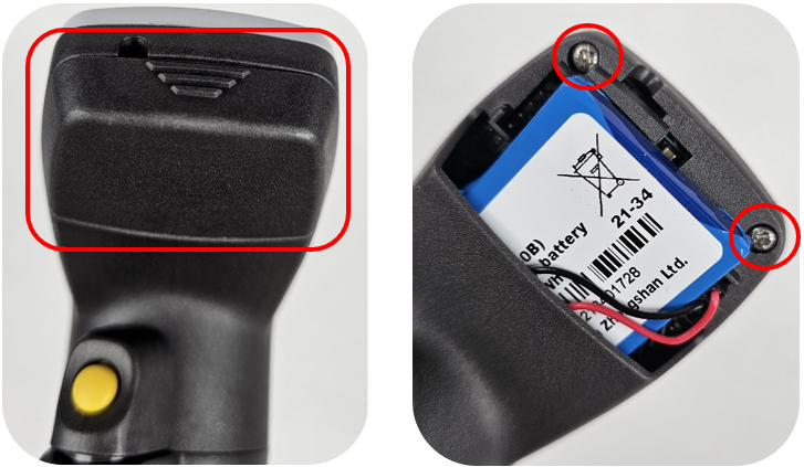
    Remove battery cover
    Step 4:

    Carefully lift the top edge away from the battery compartment. Once some space is created, use a flat-head screwdriver to pry the lower part away from the back of the pipette.
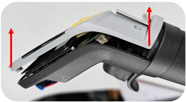
    remove Finnpipette window
    Step 5:

    After removing the light gray part/window from the pipette, hold the window with your left thumb over the red location marked in the picture below. With your right hand, gently bend the gray frame downward to create space at the bottom edge of the window.

    Note: The frame is fragile, so it is important to use your left hand to push up on the underside of the window to release the bottom tab (small rectangle outlined in the image below).
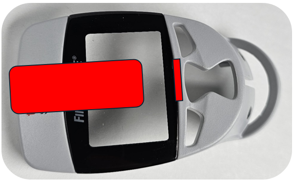
    thumb placement on Finnpipette window
    Step 6:

    Once the window is free at the bottom (see picture below), slide it away from the top edge. This step is important, as there is a thin plastic piece at the top of the frame that can easily break if you’re not careful.
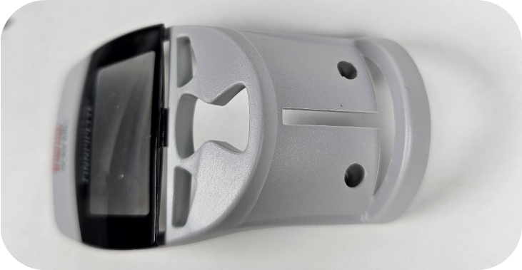
    Finnpipette window
    Step 7:

    Take the new window and insert the tab into the top of the frame. It’s important to gently bend the frame downward with your right hand to create space for the second tab. This is the same step we performed in Step 6. See the picture below that outlines the tabs on the top and bottom of the window.
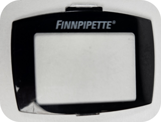
    Finnpipette window
    Step 8:

    Insert the silicone keypad into the frame. This is a good time to ensure there is no debris or fingerprints inside the window before reassembling the pipette. A cotton swab with some 70% isopropyl alcohol can be used to clean these internal surfaces.

    Note: Make sure the part is dry before reinstalling, as alcohol can damage electronic components.
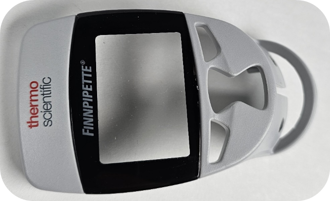
    replaced Finnpipette window
    Step 9:

    Note the channel at the bottom of the frame. This lines up with a corresponding channel on the pipette. When reattaching the frame, it’s easier to slide the frame over the ejector.
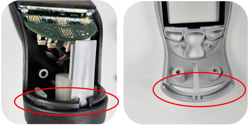
    reattaching frame
    Step 10:

    Once the frame is partially in place, focus on aligning the two channels. The best approach is to angle the frame at a 30–45-degree angle and gently push the bottom of the frame into position.
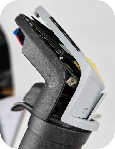
    reassembling window
    Step 11:

    Press down on the frame to ensure it is fully seated, with no gap present between the frame (light gray) and the back clamshell (dark gray). Reinstall the long screws on either side of the ejector (refer to Step 1) and the short screws above the battery in the battery compartment (refer to Step 3).
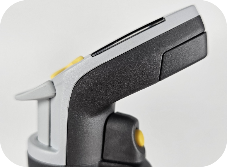
    reassembled
    Step 12:

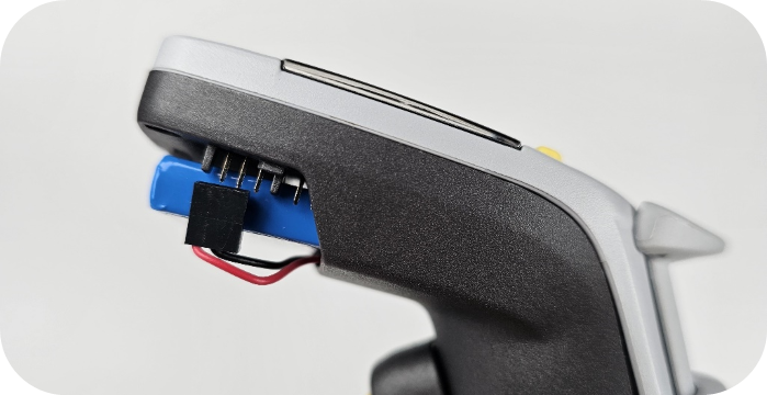
    Reattach the battery connector and battery door (refer to Step 3). Check to ensure the ejector and aspirate/dispense buttons are working properly.
    reattach battery cover

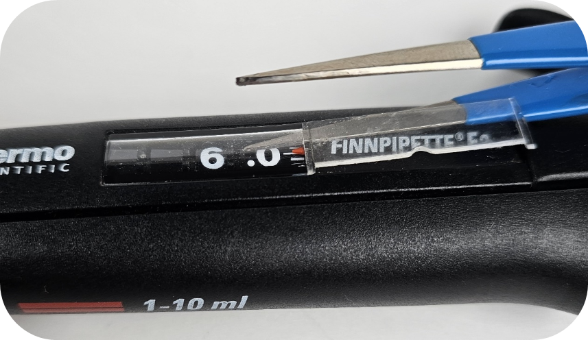
    Note: The F2, F3, and Fisherbrand Elite pipettes do not have a replacement window available. While it is possible to use a window from the same model, it is not advised, as the window has a very thin and fragile border edge that can easily be damaged during installation. If needed, you can use a flat-head screwdriver to pry out the window. If you attempt this, make sure the screwdriver is inserted far enough into the window to ensure it comes out as one piece. We have provided a picture below to demonstrate the correct position for the screwdriver/shim to limit damage to the window.
    removing window

    The following ThermoFisher Models have a machined/glued in window and can’t be replaced, see list below:

    1. Finnpipette Colour
    2. Finnpipette I
    3. Finnpipette F1 & F1 ClipTip
    Related Posts:

    Preventive Maintenance: Fisherbrand Elite Single Channel (2uL-1000uL)
    Finnpipette Novus Error Codes
    Finnpipette Digital (Model 4500) Single Channel: How to Service and Replace the Tip Ejector Assembly
    Finnpipette F1 and F2 Tip Ejector Mechanism Replacement

    Disclaimer: Any action you take using the information on this website is strictly at your own risk. The information herein does not constitute professional advice and is general in nature. We make no warranty that this information will meet your requirements, be safe, accurate, or error-free. Pipette Supplies, Inc. is not responsible for any errors or omissions, any results obtained from the use of this information, or any loss or damage arising out of the use of this information. This site is for educational purposes only.
    Fair Use: Copyright Disclaimer under section 107 of the Copyright Act of 1976, allows for “fair use” for purposes such as comments, criticism, teaching, scholarship, news reporting, and research.
    Fair use is permitted by copyright statute that might otherwise be infringing.
  • Preventive Maintenance: Fisherbrand Elite Single Channel (2uL-1000uL)

    The process of disassembly, removing, replacing, and reinstalling parts, as well as, performing preventive maintenance (PM) on the Fisherbrand Elite single channel pipette requires great care. A high attention to detail, patience, and steady hands are required. Please dedicate a good work area with good lighting and space where small parts can be located should they fly out during disassembly. Pipette damage and lost parts may occur if attention to detail is not maintained. Please proceed at your own risk.

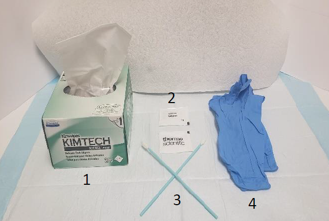
    Recommended Tools:
    1. Box of Kim Wipes
    2. Thermo Scientific Lubricant (Part#: TS 3300200)
    3. 2-3 Foam Swabs (applying new lubricant)
    4. Pair of latex gloves
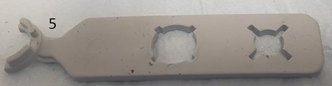
    5. PM/Calibration Tool (Part#: TS 1062800)
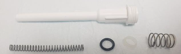
    6. Fisherbrand Elite Replacement Parts
    recommended tools
    PM/Calibration Tool (Part#: TS 1062800)
    Disassembly Process for PM and Part Replacement
    Step 1:

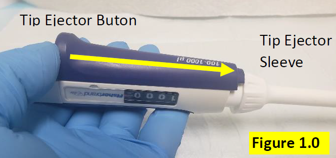
    Press and hold down the tip ejector button, in order to lower the white colored tip ejector sleeve. Figure 1.0.

    Remove Fisherbrand Elite tip ejector button
    Step 2:

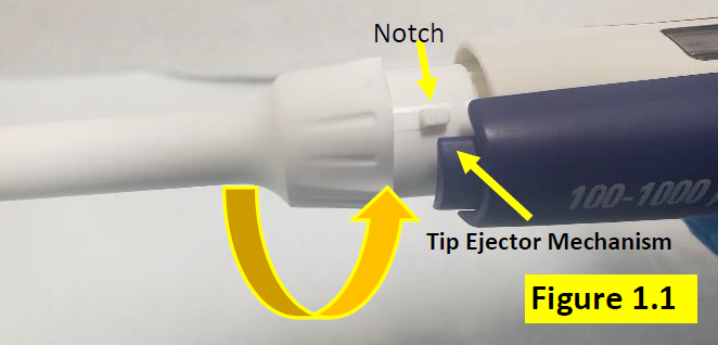
    Twist and turn the tip ejector sleeve to disengage it from the pipette body. Notice the square notch will become visible when properly disengaged from the pipette body, tip ejector mechanism. Figure 1.1.

    Notch on tip ejector
    Step 3:

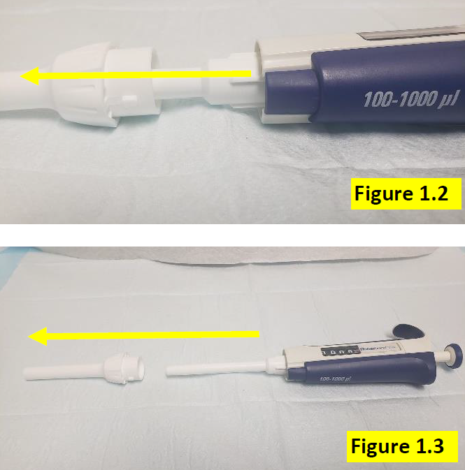
    Once tip ejector sleeve is disengaged, slide it down and off of the pipette shaft, as shown in Figure 1.2 and 1.3.

    Removing the ejector
    Step 4:

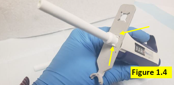
    With the tip ejector sleeve removed, insert the PM portion of the calibration tool over the shaft until it aligns with the slit marks on the upper portion of the shaft. Figure 1.4.

     Using the Fisherbrand Elite PM tool
    Step 5:

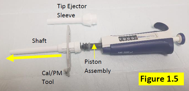
    Rotate the PM/Calibration tool counter clockwise to fully disengage the shaft from the pipette body. Figure 1.5.


    CAUTION: The contents inside of the shaft are under spring pressure. Use caution to avoid small parts and springs from popping out of the pipette/shaft, forcefully.

    Disassembled Fisherbrand Elite lower part
    Step 6:

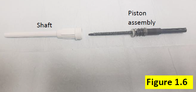
    With the shaft fully removed from the pipette body, gently slide out and remove the black colored internal piston assembly. Figure 1.6.


    When removing, ensure the following internal piston components are accounted for:

    • Large piston spring
    • Smaller o-ring spring
    • Plastic spring support
    • Piston o-ring
    Disassembled Fisherbrand Elite shaft
    Step 7:

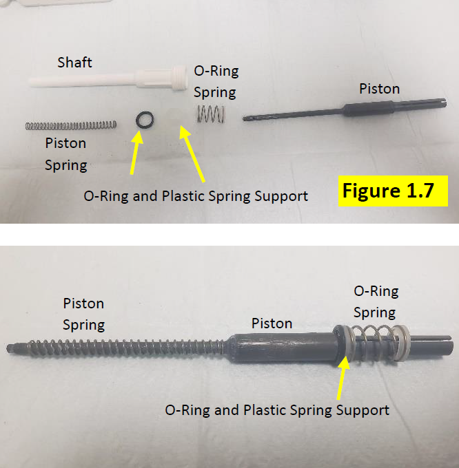
    Remove all of the internal piston assembly components (Figure 1.7) for inspection, cleaning, and replacement as necessary. See Fisherbrand Elite Replacement Parts for these parts:

    • Large piston spring
    • Smaller o-ring spring
    • Plastic spring support
    • Piston o-ring
    • Lubricant
    • PM/Calibration tool
    Disassembled piston assembly
    Step 8:

    Inspect, clean, and replace the parts as necessary. Fisherbrand Elite Replacement Parts

    Possibly parts for replacment
    Step 9:

    Clean and remove the old lubricant from the piston with a clean kim wipe. Repeat as necessary and dab the kim wipe with IPA if needed to remove lubricant.


    Step 10:

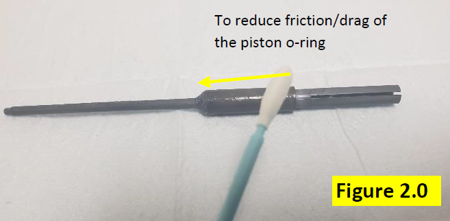
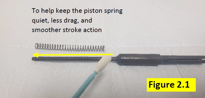
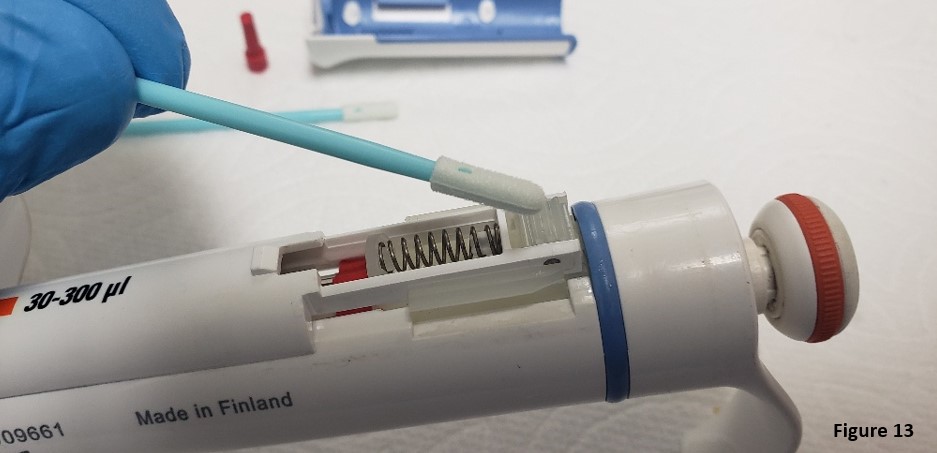
    Use a foam swab and apply a light but visible coating of lubricant onto the piston assembly. See figures 2.0 and 2.1 USE THE CORRECT LUBRICANT (Part#: TS 3300200).

    Adding lubricant to Fisherbrand Elite piston assembly
    lubricant application tips
    Reassembly Process After PM and Part(s) Replacement
    Step 11:

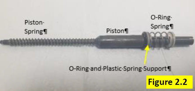
    Install inspected, cleaned, and/or new part(s) back onto the piston, as shown in Figure 2.2.

    Reassembled Fisherbrand Elite piston assembly
    Step 12:

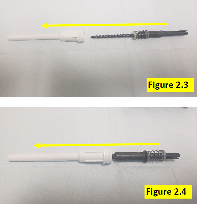
    Insert the piston assembly back into the shaft assembly. Figure 2.3 and 2.4.

    Reassembling the lower part
    Step 13:

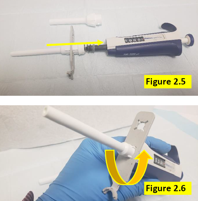
    With the piston assembly back inside the shaft, use the PM portion of the calibration tool to screw the shaft dully onto the pipette body. Figures 2.5 and 2.6. DO NOT OVER TIGHTEN.

    Reassembling the Fisherbrand Elite lower part
    Step 14:

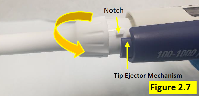
    Press the tip ejector button down and attach the tip ejector sleeve to the tip ejector mechanism. Rotate so the notch aligns and secures to the tip ejector mechanism. Figure 2.7.

    Aligning the notch
    Step 15:

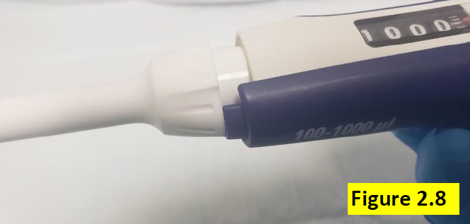
    Figure 2.8 shows notch has been rotated and now secured to the tip ejector mechanism.

    Secured Fisherbrand Elite tip ejector
    Step 16:

    Once pipette is fully assembled, allow the pipette to equilibrate for at least 60 minutes. After 60-minute equilibration period, verify the accuracy and precision on a 4-5 place gravimetric place balance.

    Related Posts:
    Finnpipette F1 and F2 Tip Ejector Sleeve Replacement
    Finnpipette Novus Error Codes
    Non-Linear Volume Readings – When Should A Calibration Adjustment Be Made?
    Top 10 Crimes Committed Against Pipettes

    Disclaimer: Any action you take using the information on this website is strictly at your own risk. The information herein does not constitute professional advice and is general in nature. We make no warranty that this information will meet your requirements, be safe, accurate, or error-free. Pipette Supplies, Inc. is not responsible for any errors or omissions, any results obtained from the use of this information, or any loss or damage arising out of the use of this information. This site is for educational purposes only.
    Fair Use: Copyright Disclaimer under section 107 of the Copyright Act of 1976, allows for “fair use” for purposes such as comments, criticism, teaching, scholarship, news reporting, and research.
    Fair use is permitted by copyright statute that might otherwise be infringing.
  • Finnpipette F1 and F2 Tip Ejector Sleeve Replacement

    warning

    The process of removing, replacing, and reinstalling the F1 tip ejector sleeve requires great care, a high attention to detail, patience, and steady hands. Please dedicate a good work area with good lighting and space where small parts can be located should they pop/fly out during disassembly. Pipette damage and lost parts may occur if attention to detail is not maintained. Please proceed at your own risk.

    Replacement Parts:

    Finnpipette F1 Single Channel
    Finnpipette F2 Single Channel

    Disassembly Process:
    Step 1:

    Press down and hold the tip ejector button. This will lower the tip ejector sleeve for disassembly.

    NOTE:

    See ‘Replacement Parts’ above for F1 and F2 Tip Ejector Sleeve replacement parts, including ejectors.

    F1 tip ejector button depressed
    Step 2:

    Grasp the tip ejector sleeve and gently twist to the left to disengage it from the pipette body.

    Turn ejector to the left
    Step 3:

    Once disengaged slide it down and away from the shaft.

    Remove F1 tip ejector
    Reassembly Process
    Step 4:

    Slide the new tip ejector sleeve up the shaft.

    Replace the tip ejector
    Step 5:

    Press down and hold the tip ejector button.

    Depress the ejector button
    Step 6:

    Twist the tip ejector sleeve gently to the right to engage it with the pipette body.

    Engage F1 tip ejector button by twisting to the right
    Related Posts:

    Finnpipette F1 and F2 Tip Ejector Mechanism Replacement
    Finnpipette Digital (Model 4500) Single Channel: How to Service and Replace the Tip Ejector Assembly
    Pipette Parts – Life Span, Life Cycle, and Performance
    Finnpipette Novus Error Codes

    Disclaimer: Any action you take using the information on this website is strictly at your own risk. The information herein does not constitute professional advice and is general in nature. We make no warranty that this information will meet your requirements, be safe, accurate, or error-free. Pipette Supplies, Inc. is not responsible for any errors or omissions, any results obtained from the use of this information, or any loss or damage arising out of the use of this information. This site is for educational purposes only.
    Fair Use: Copyright Disclaimer under section 107 of the Copyright Act of 1976, allows for “fair use” for purposes such as comments, criticism, teaching, scholarship, news reporting, and research.
    Fair use is permitted by copyright statute that might otherwise be infringing.
  • Finnpipette Novus Error Codes

    Novus Error Codes – Decoded!

    Error CodeDescription
    11Eeprom checksum-problem. In case it repeats, change main CB assy
    12Motor home positioning error (stuck module, failure in Opto CB assy or broken main CB assy)
    13Software bug
    14Pipette overheated
    15Battery low or battery empty or battery disconnected (SW version 4.0)
    16Dispensing cycle is interrupted or Battery disconnected (SW version 4.1)


    Replacement Parts:
    Finnpipette Novus Single Channel Parts
    Finnpipette Novus Multichannel Parts

    Novuse Error Code on single channel

    Related Posts:
    Finnpipette F1 and F2 Tip Ejector Mechanism Replacement
    Finnpipette Digital (Model 4500) Single Channel: How to Service and Replace the Tip Ejector Assembly
    The Reality of Electronic Pipette Calibration
    Electronic Pipette Error Message

    Disclaimer: Any action you take using the information on this website is strictly at your own risk. The information herein does not constitute professional advice and is general in nature. We make no warranty that this information will meet your requirements, be safe, accurate, or error-free. Pipette Supplies, Inc. is not responsible for any errors or omissions, any results obtained from the use of this information, or any loss or damage arising out of the use of this information. This site is for educational purposes only.
    Fair Use: Copyright Disclaimer under section 107 of the Copyright Act of 1976, allows for “fair use” for purposes such as comments, criticism, teaching, scholarship, news reporting, and research.
    Fair use is permitted by copyright statute that might otherwise be infringing.
  • Finnpipette F1 and F2 Tip Ejector Mechanism Replacement

    Warning

    The process of removing, replacing, and reinstalling the F1 tip ejector pusher upper and lower slide mechanisms require great care, a high attention to detail, patience, and steady hands. Please dedicate a good work area with good lighting and space where small parts can be located should they pop/fly out during disassembly. Pipette damage and lost parts may occur if attention to detail is not maintained. Please proceed at your own risk.

    Finnpipette F1 and F2 Tip Ejector Mechanism Replacement – Pusher Upper Part and Lower Slide.

    These instructions are applicable for both single channel and multichannel Finnpipette F1, F1 ClipTip, and F2 pipettes.

    Disassembly Process:

    Step 1:

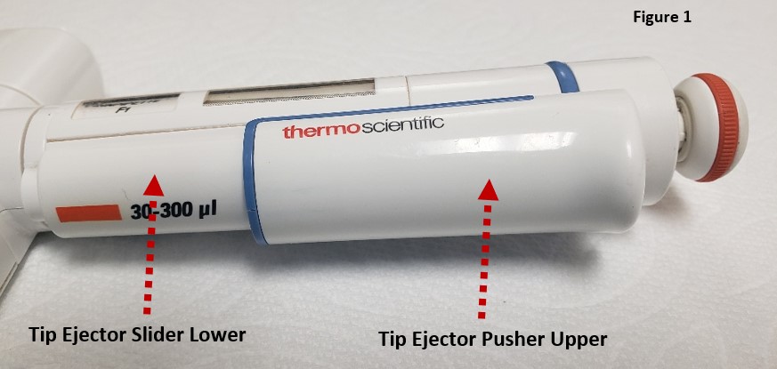
    The ejector mechanism is made up of two components: the tip ejector pusher upper part and the tip ejector slider lower part. Check and become familiar with these parts.

    F1 / F2 ejector pieces
    Step 2:

    Press the ejector button down and hold.

    Press and hold the tip ejector button down
    Step 3:

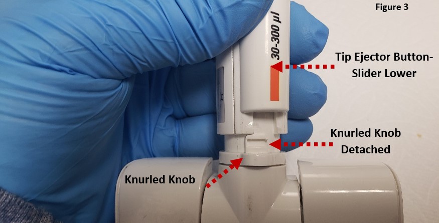
    Gently rotate the white colored knurled knob clockwise to detach it from the tip ejector slider lower part.

    Rotate and detach the tip ejector assembly
    Step 4:

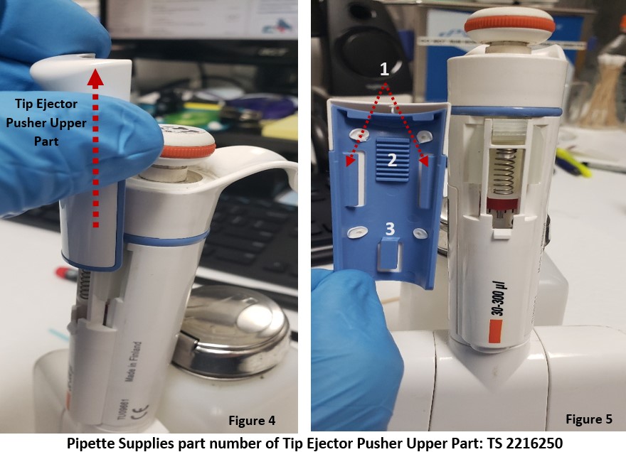
    With your thumb, gently push upward on the tip ejector pusher upper part to separate it from the tip ejector slider lower piece, per figure 4.

    Note: You may need to use a small-bladed tool like a screwdriver to gently pry up one side of the tip ejector upper part if it does not come detached when pressing upward with your thumb. See figure 4.

    Notice: The blue colored backside of the tip ejector pusher upper part contains:

    1. Left & Right-side rail tabs.
    2. Grooved cog wheel lines.
    3. Lower locking tab

    Ensure none are broken off or missing. If so, replace.

    Remove the ejector upper part

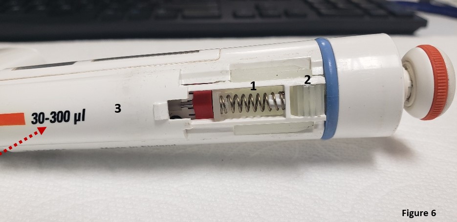
    Observation: With the tip ejector pusher upper part removed, notice the components of the tip ejector slider lower part:

    1. Tip ejector spring: (TS 1132820)
    2. Cog wheel: (TS 1063370)
    3. Tip ejector slider lower part: (varies based on imprinted volume size [F1, F2])

    These parts may pop off and get lost, be careful.

    Internal components of Finnpipette F1 / F2 tip ejector mechanism
    Step 5:

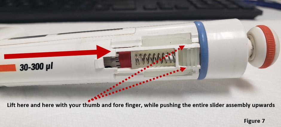
    Gently lift outwards the cog wheel assembly, while pushing the entire tip ejector slider assembly lower part upward.

    Lift out the Finnpipette F1 / F2 lower part

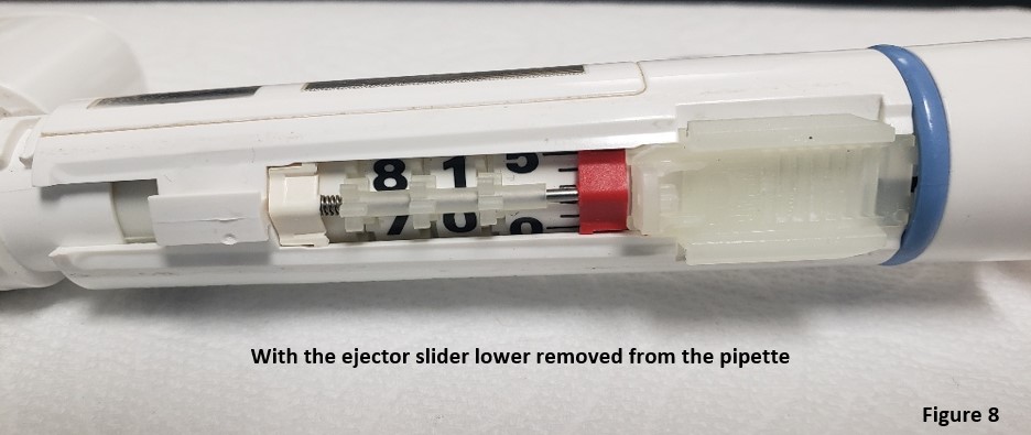
    With the ejector slider lower part removed, the pipette will look as pictured in figure 8.

    View of Finnpipette F1 / F2 with lower ejector part removed

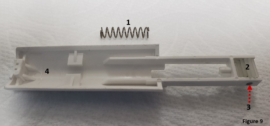
    Step 6:  Remove and replace parts (F1, F2) as needed:

    1. Tip ejector slider spring
    2. Cog Wheel
    3. Cog Wheel Pin
    4. Tip ejector slider lower assembly
    Detached tip ejector lower part

    Reassembly Process:

    Step 7

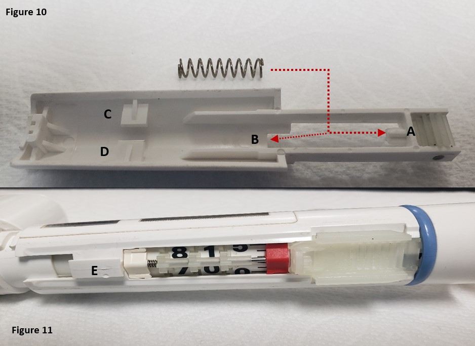
    Insert new or existing spring back onto the upper (A) and lower (B) posts as shown in figure 10. Replace the pin in the cog wheel and then the cog wheel itself, as needed.

    Notice: Support tabs C and D in figure 10 will be fitted into post E on the pipette body.

    Finpipette F1 removed lower ejector and open pipette

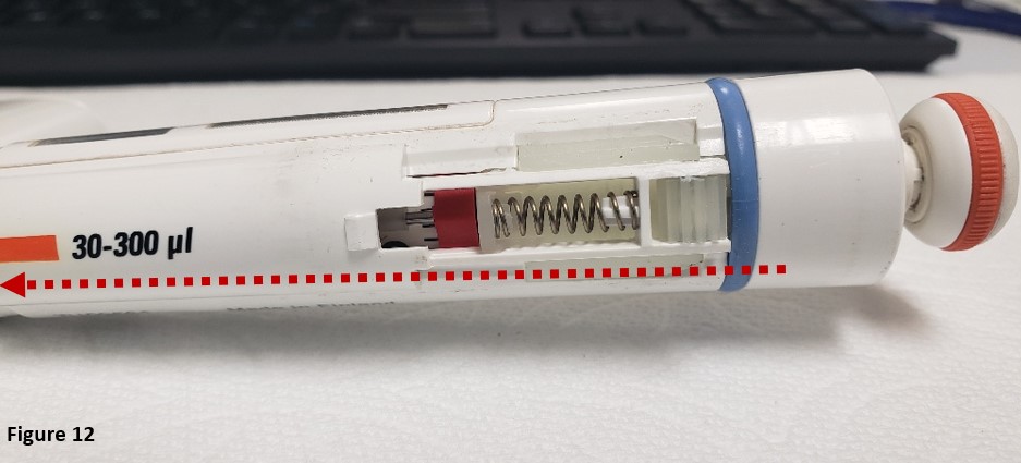
    Step 8: Align tabs C & D into post E from figures 10 and 11. Fully slide the Finnpipette F1 / F2 tip ejector slider lower part back onto the pipette body as shown in figure 12.

    Reattaching the lower tip ejector
    Step 9:

    As recommended by ThermoScientific Technical Support, place a “minute” amount of TS 3300200 1g grease onto a foam swab or lint-free towel. Very lightly grease the cog wheel with a very small of grease.

    Apply grease to cog wheel
    Step 10:

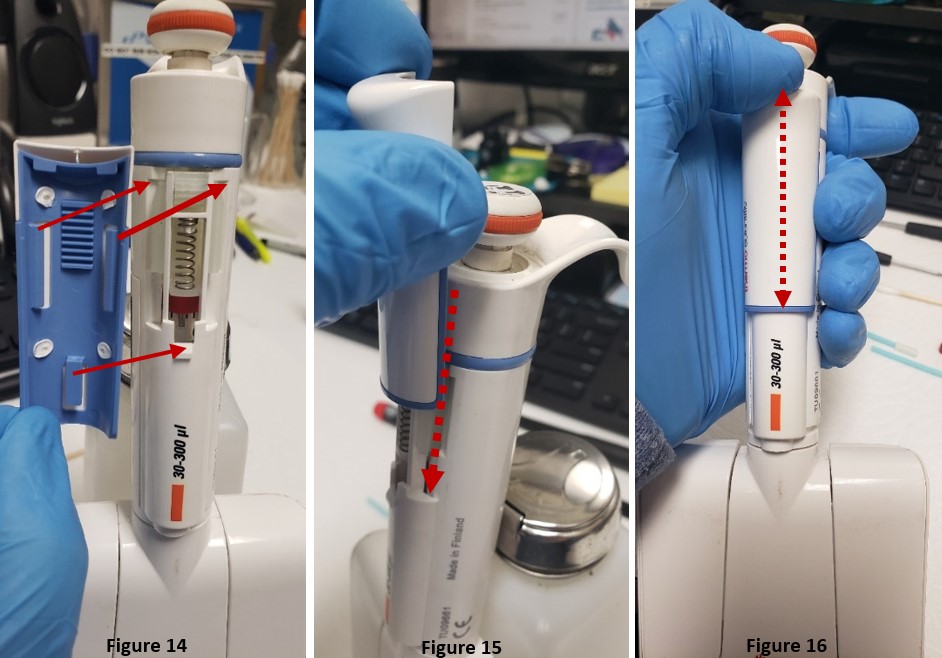
     Refer to step 4, figure 5 by aligning the left and right-side tabs with the pipette ejector slider lower part, as in figure 14.

    Step 11:

    Slide the ejector pusher upper part back onto the pipette, as shown in figure 15. It should snap/click back into place once seated properly.

    Step 12:

    Lastly, press the tip ejector button a few times to ensure it is seated and working properly (Figure 16). Then test by loading and ejecting tips. Recheck your work, if needed.

    Reattaching the Finnpipette F1 upper tip ejector part

    Related Posts:
    Finnpipette Digital (Model 4500) Single Channel: How to Service and Replace the Tip Ejector Assembly
    Finnpipette Novus Error Codes
    Types of Pipette Tips
    Pipette Parts – Life Span, Life Cycle, and Performance

    Disclaimer: Any action you take using the information on this website is strictly at your own risk. The information herein does not constitute professional advice and is general in nature. We make no warranty that this information will meet your requirements, be safe, accurate, or error-free. Pipette Supplies, Inc. is not responsible for any errors or omissions, any results obtained from the use of this information, or any loss or damage arising out of the use of this information. This site is for educational purposes only.
    Fair Use: Copyright Disclaimer under section 107 of the Copyright Act of 1976, allows for “fair use” for purposes such as comments, criticism, teaching, scholarship, news reporting, and research.
    Fair use is permitted by copyright statute that might otherwise be infringing.
  • Finnpipette Digital (Model 4500) Single Channel: How to Service and Replace the Tip Ejector Assembly

    In this post:

    Finnpipette Digital Tip Ejector Pusher Mechanism: Based on imprinted volume size on mechanism. Does not include cog wheel or spring. Shop tip ejector pushers.
    Tip Ejector SpringTS 1131820
    Tip Ejector Button TS 10593000
    Cog Wheel TS 10593060

    (The Finnpipette Digital Single Channel is the same pipette as the Finnpipette Model 4500 Single Channel)

    Background Overview:

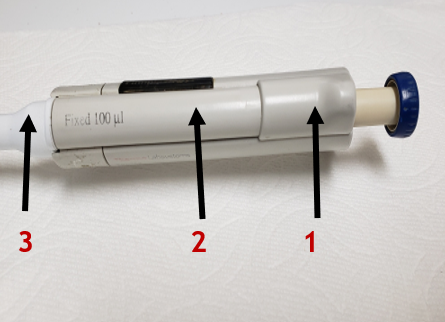
    1. Tip Ejector Button: Cog wheel is hidden from view and on underside of tip ejector button
    2. Tip Ejector Pusher Mechanism: Ejector spring is hidden from view on underside of ejector pusher mechanism
    3. White Colored Tip Ejector Sleeve: Ejector sleep fits over the shaft and allows the tips to be ejected.
    Finnpipette Digital tip ejector button, tip ejector mechanism, tip ejector sleeve
    Finnpipette Model 4500: How to Service and Replace the Tip Ejector Assembly
    Step 1:

    Gently pull downward on the white colored tip ejector sleeve until it disengages from the tip ejector assembly. Once removed, lay aside for reassembly later.

    Step 2:

    (Figure 1.0) Gently press upward on the tip ejector button with your thumb until it disengages from the lower portion of tip ejector mechanism. Once removed, lay the ejector button aside for reassembly later.

    NOTE: (Figure 1.1) Notice the cog wheel is now visible once the ejector button is removed. Please be careful to not lose the cog when the tip ejector pusher mechanism is removed in step 3.

    Figure 1.0 and 1.1. Push upward on the tip ejector button. Notice cog wheel.
    Step 3:

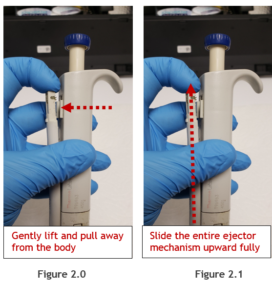
    (Figure 2.0) Gently and carefully pull the upper portion of tip ejector pusher mechanism outward and away from the pipette body. Pull just enough so the cog wheel and upper portion of the ejector pusher mechanism no longer contacts the pipette body.

    Figure 2.0 and 2.1.Gently lift and pull away from the body. Slide the entire ejector mechanism upward fully.
    Step 4:

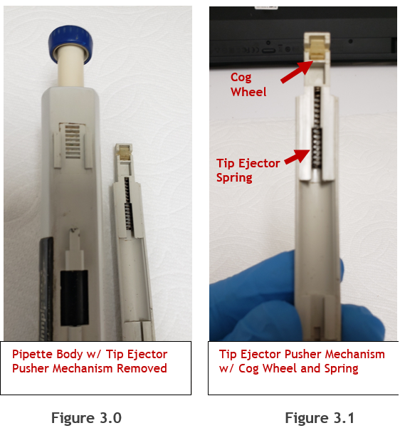
    (Figure 2.1) While holding the cog wheel and upper portion of the ejector pusher assembly away from the pipette body, slide the entire ejector pusher mechanism upward to disengage it fully from the body. Once disengaged, lay aside, as shown in figure 3.0.

    Figure 3.0 and 3.1. Pipette body with tip ejector removed. Pusher mechanism with cog wheel and spring.
    Note: In figures 3.0 and 3.1, notice the cog wheel and tip ejector spring positions/orientation. These parts can be removed for cleaning with 70% IPA and a soft bristled toothbrush. If needed, replacement parts can be found at Pipette Supplies:
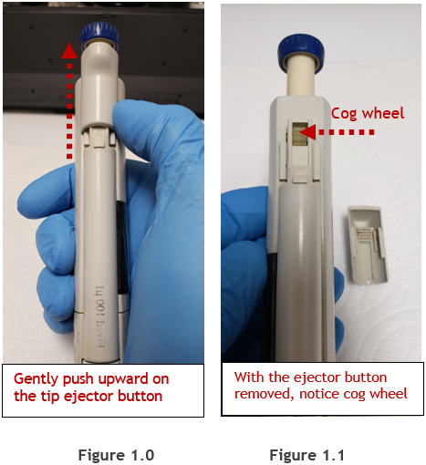
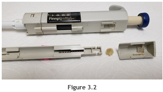
    Figure 3.2: Exploited view of the ejector button, cog wheel, tip ejector pusher mechanism, and spring removed from the pipette for easier viewing purposes.

    Figure 3.2. Disassembled tip ejector system

    Reassembly Process:

    Step 5:

    Re-install the tip ejector spring and cog wheel back onto the tip ejector pusher mechanism.

    Step 6:  

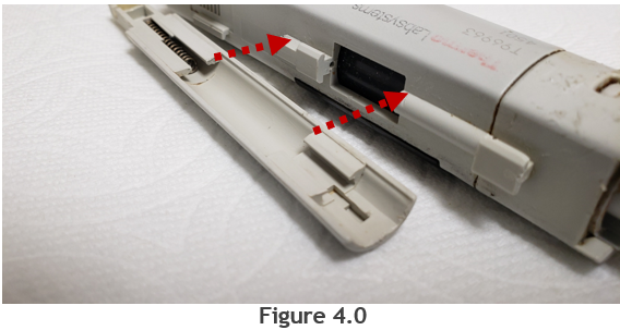
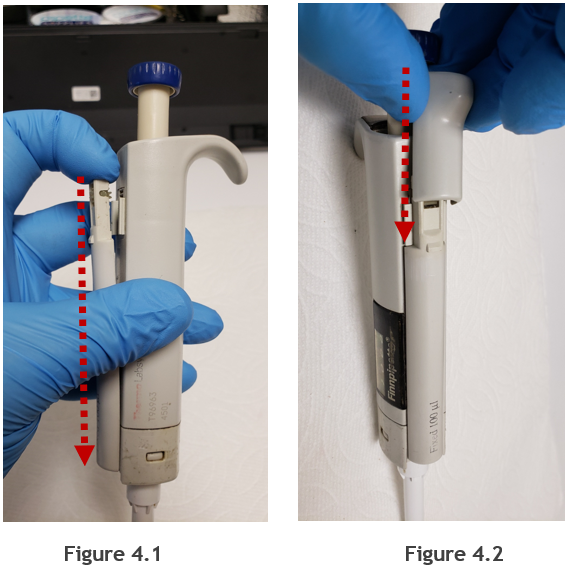
    Align the tip ejector mechanism slits with the slots on the pipette handle, as shown in figure 4.0. Push the tip ejector pusher mechanism downward until it is fully seated back onto the pipette (Figure 4.1).

    Figure 4.0. Removed ejector pusher
    Step 7:

    (Figure 4.2) Re-install the tip ejector button onto the tip ejector pusher mechanism by pushing downward.

    Figure 4.1 and 4.2. Reassembling the tip ejector system
    Step 8:

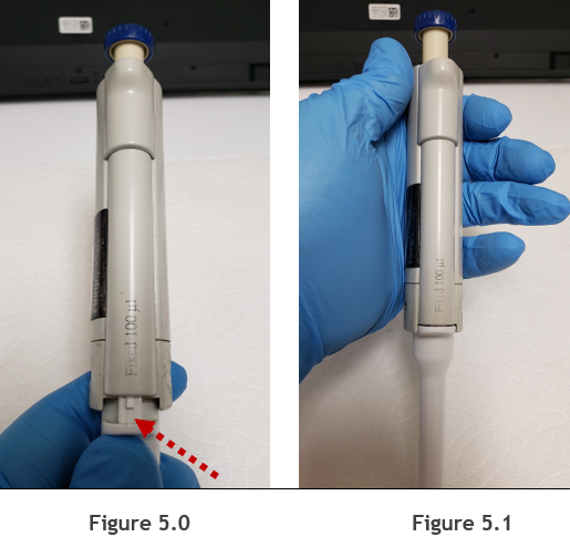
    (Figure 5.0) Re-install the white colored tip ejector back onto the pipette by aligning it with the tip ejector pusher mechanism. Once aligned, push upward until it is secure.

    Step 9:

    (Figure 5.1) Check reassembly by loading and ejecting tips multiple times. Re-check your work as needed.

    Figure 5.0. Reassembling the ejector sleeve.

    Disclaimer: Any action you take using the information on this website is strictly at your own risk. The information herein does not constitute professional advice and is general in nature. We make no warranty that this information will meet your requirements, be safe, accurate, or error-free. Pipette Supplies, Inc. is not responsible for any errors or omissions, any results obtained from the use of this information, or any loss or damage arising out of the use of this information. This site is for educational purposes only.
    Fair Use: Copyright Disclaimer under section 107 of the Copyright Act of 1976, allows for “fair use” for purposes such as comments, criticism, teaching, scholarship, news reporting, and research.
    Fair use is permitted by copyright statute that might otherwise be infringing.