Category: Drummond

  • Drummond Scientific Repair Videos

    Drummond repair videos can be found on Drummond’s Resource page.

    Find Drummond repair parts here!

    Videos include:

    • Portable Pipet-Aid Nosepiece Filter Replacement – Part 1 & 2
    • Portable Pipet-Aid Battery Replacement – Part 1, 2, & 3
    • Pipet-Aid XP O-Rings Replacement
    • Pipet-Aid XP Filter Replacement
    • Pipet-Aid XP Nosepiece Filter Replacement – Part 1 & 2
    • Pipet-Aid XP Battery Replacement – Part 1 & 2
    • Pipet-Aid XL Filter Replacement
    Drummond logo

    Disclaimer: Any action you take using the information on this website is strictly at your own risk. The information herein does not constitute professional advice and is general in nature. We make no warranty that this information will meet your requirements, be safe, accurate, or error-free. Pipette Supplies, Inc. is not responsible for any errors or omissions, any results obtained from the use of this information, or any loss or damage arising out of the use of this information. This site is for educational purposes only.
    Fair Use: Copyright Disclaimer under section 107 of the Copyright Act of 1976, allows for “fair use” for purposes such as comments, criticism, teaching, scholarship, news reporting, and research.
    Fair use is permitted by copyright statute that might otherwise be infringing.
  • Drummond Diaphragm Replacement

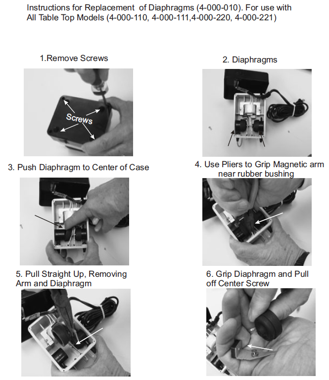
    Drummond Diaphragm Replacement Instructions

    Drummond Diaphragm and Hinge Kit: DR 4-000-010

    Table Top Models: DR 4-000-110, DR 4-000-111, DR 4-000-220, DR 4-000-221

    Instructions for Drummond Diaphragm Replacement. Step 1: remove screws. Step 2: Diaphragms. Step 3: Push diaphragm to center of case. Step 4: Use pliers to grip magnetic arm near rubber bushing. Step 5: pull straight up, removing arm and diaphragm. Step6: grip diaphragm and pull off center screw
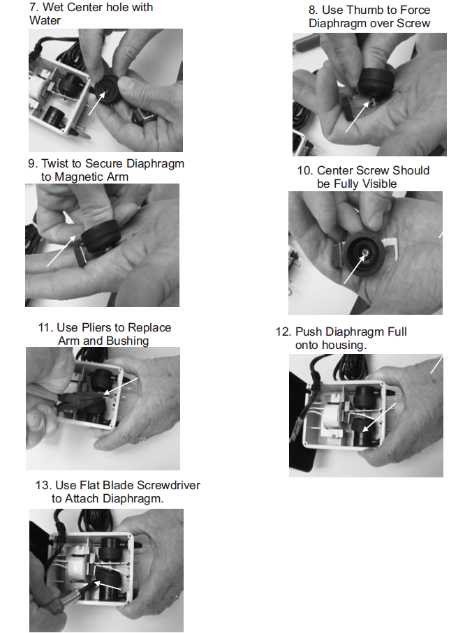
    Step 7: wet center hole with water. Step 8: use thumb to force diaphragm over screw. Step 9: twist to secure diaphragm to magnetic arm. Step 10: center crew should be fully visible. Step 11: use pliers to replace arm and bushing. Step 12: Push diaphragm full onto housing. Step 13: use flat blade screwdriver to attach diaphragm.

    Disclaimer: Any action you take using the information on this website is strictly at your own risk. The information herein does not constitute professional advice and is general in nature. We make no warranty that this information will meet your requirements, be safe, accurate, or error-free. Pipette Supplies, Inc. is not responsible for any errors or omissions, any results obtained from the use of this information, or any loss or damage arising out of the use of this information. This site is for educational purposes only.
    Fair Use: Copyright Disclaimer under section 107 of the Copyright Act of 1976, allows for “fair use” for purposes such as comments, criticism, teaching, scholarship, news reporting, and research.
    Fair use is permitted by copyright statute that might otherwise be infringing.
  • Pipet-Aid XP Pump and Wire Harness Replacement

    Pipet-Aid XP Pump and Wire Harness Replacement Instructions:

    Pipet-Aid XP
    Motor and Pump
    Wire Harness with Switch & Terminals

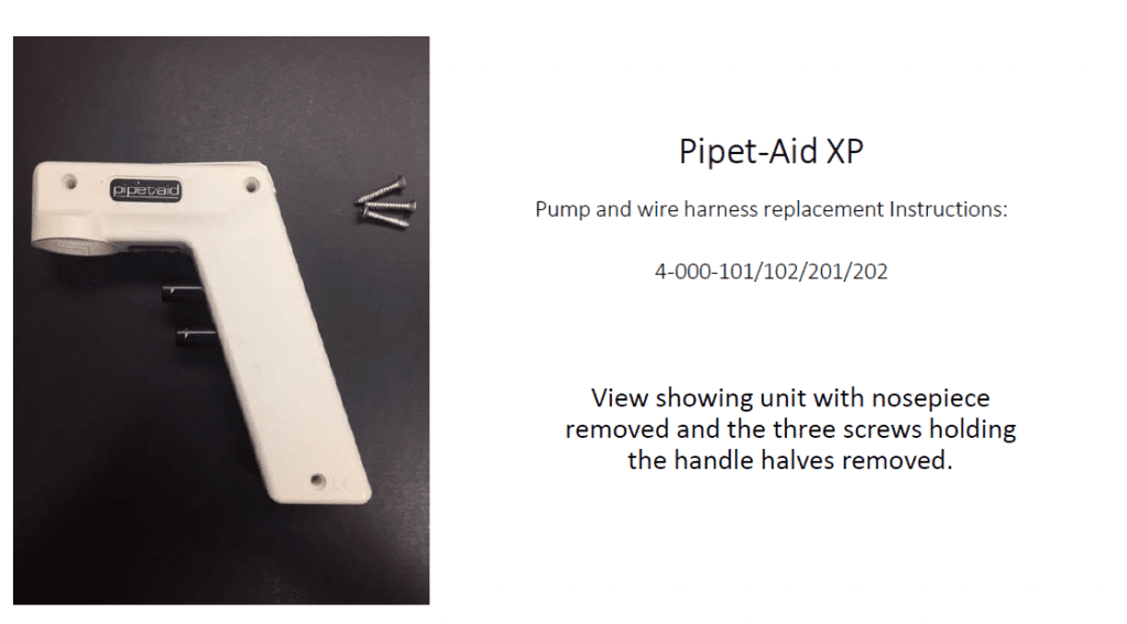
    view showing unit with nosepiece removed and the three screws holding the handle halves removed
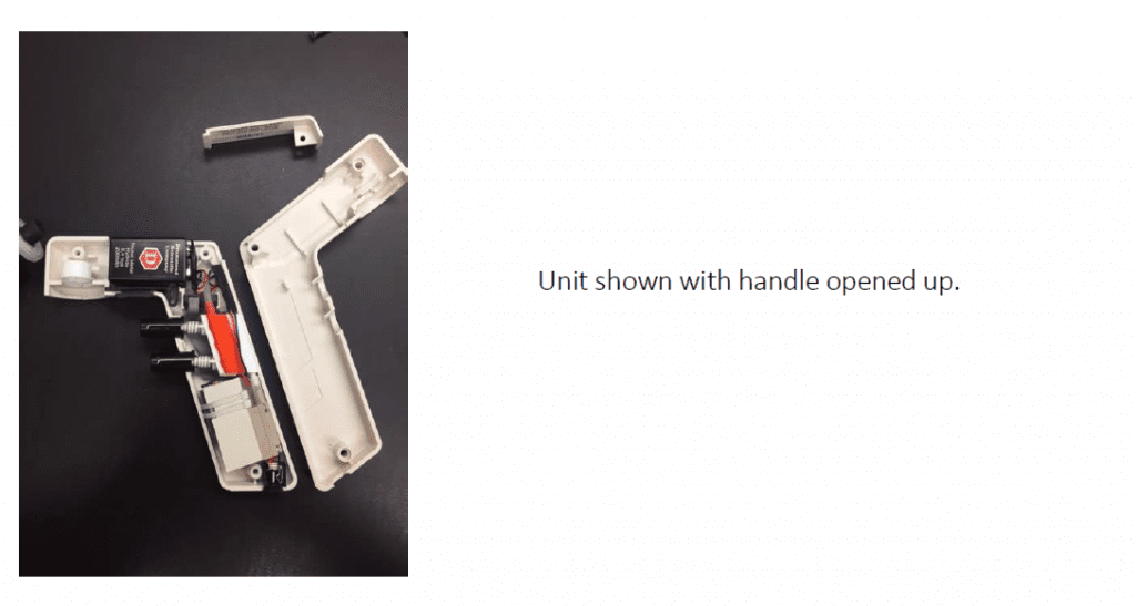
    unit shown with handle open
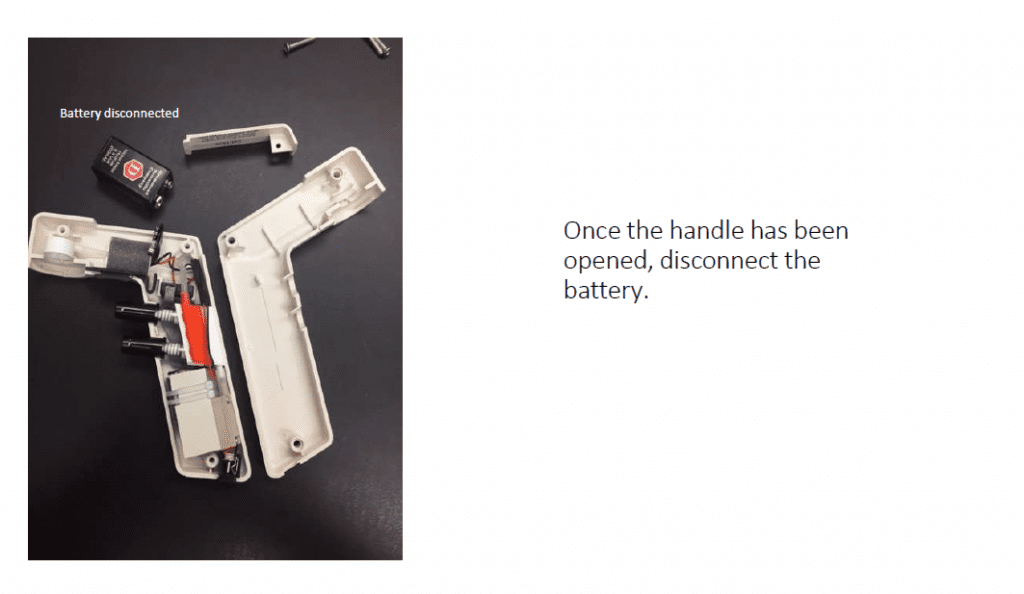
    once the handle has been opened, disconnect the battery
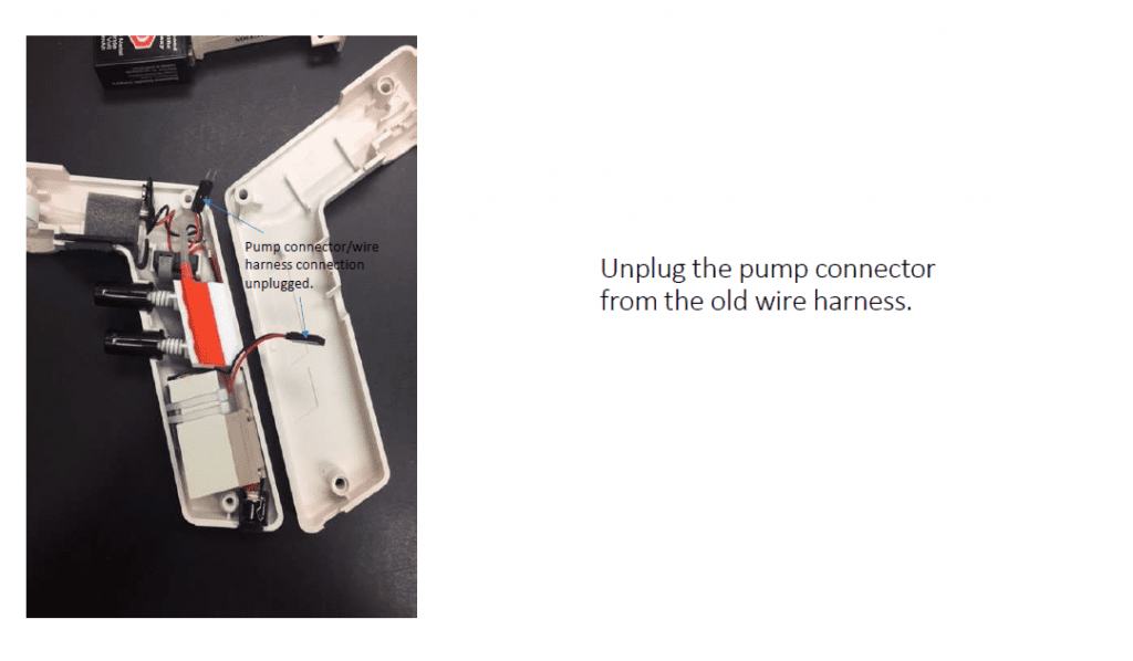
    unplug the pump connector from the old wire harness
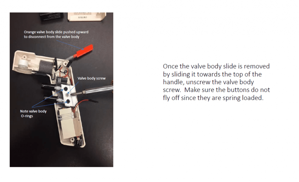
    Once the valve body slide is removed by sliding it towards the top of the handle, unscrew the valve body screw. Make sure the buttons do not fly off once they are spring loaded.
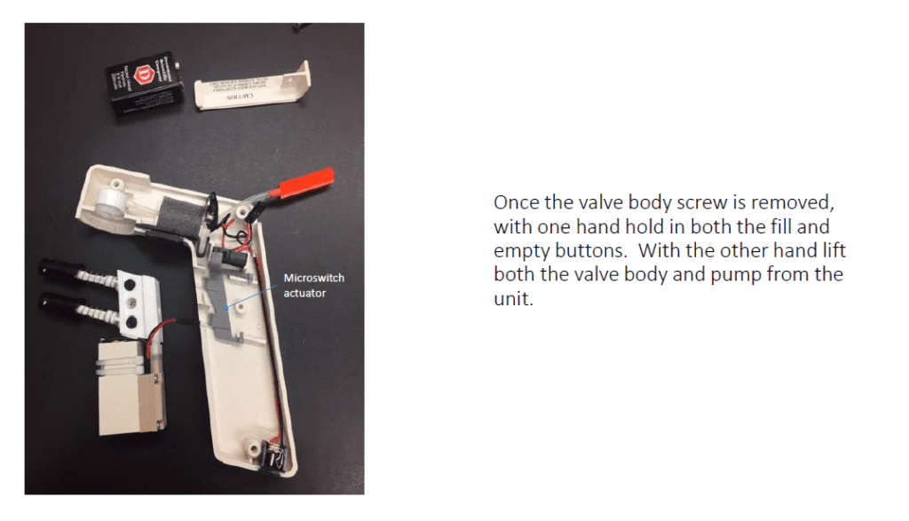
    Once the valve body screw is removed, with one hand, hold in both the fill and empty buttons. With the other hand. lift both the valve body and pump from the unit.
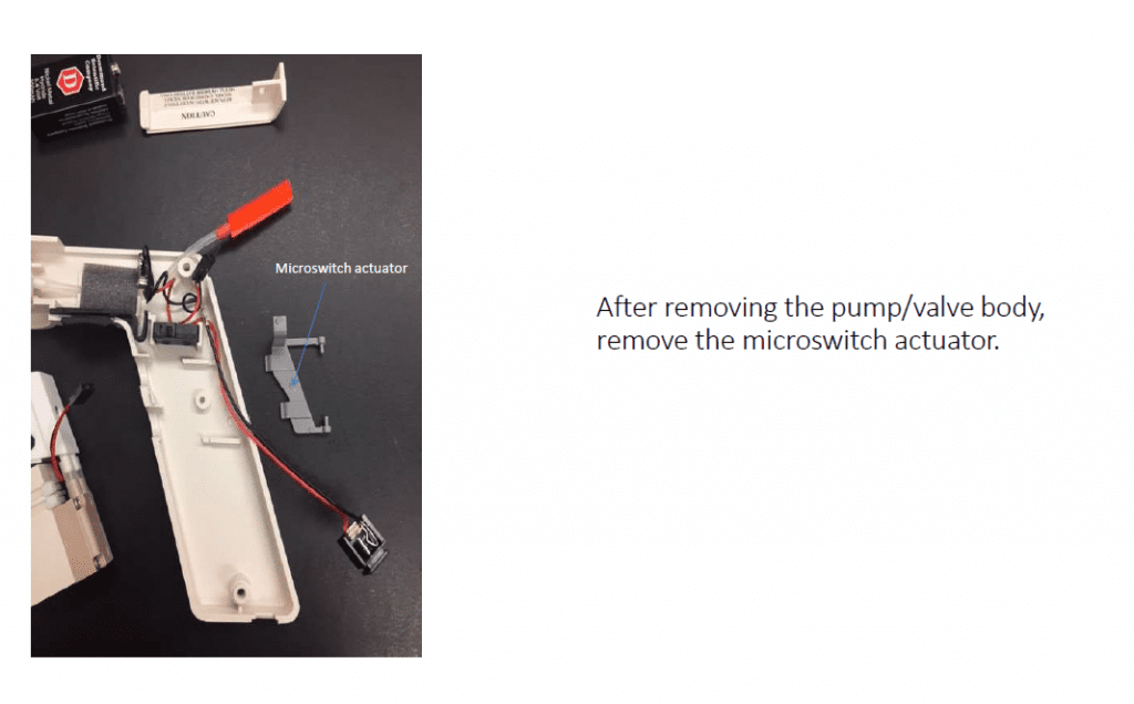
    After removing the pump/valve body, remove the microswitch actuator
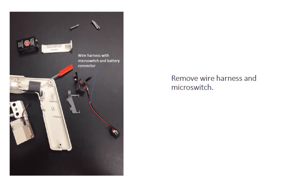
    remove wire harness and microswitch
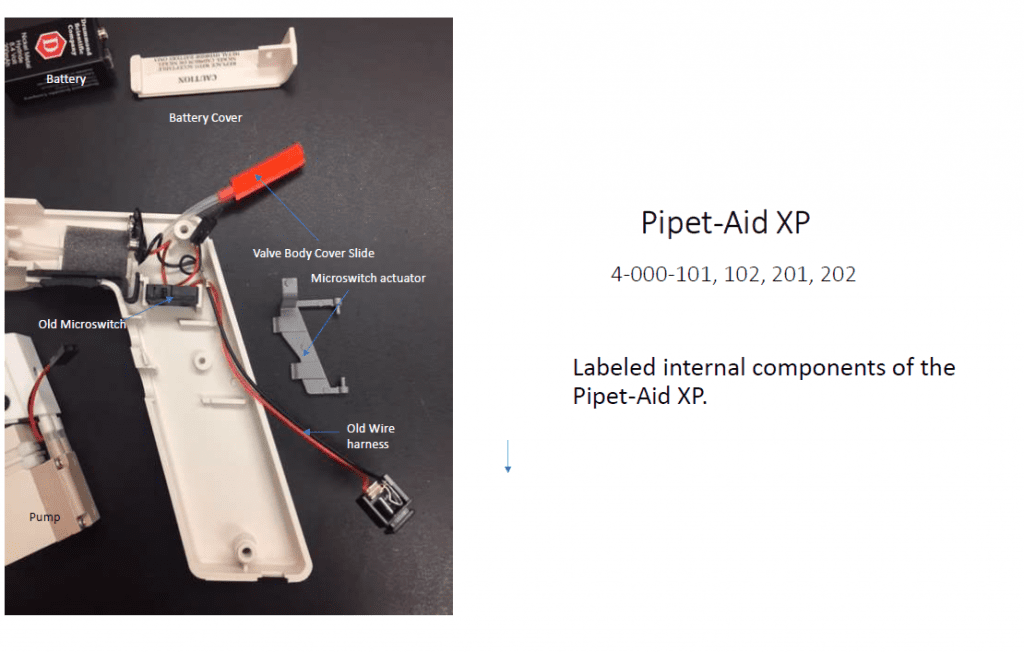
    labeled internal components of the Drummond Pipet-Aid XP
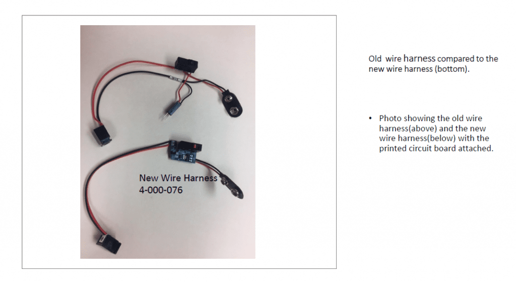
    old wire harness compared to the new wire harness with the printed circuit board attached.
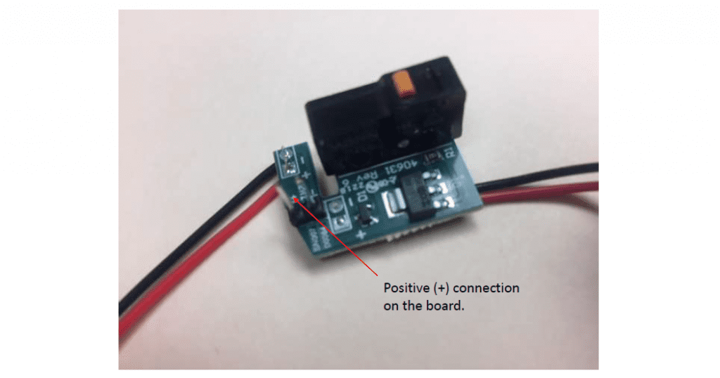
    Positive connection on the board
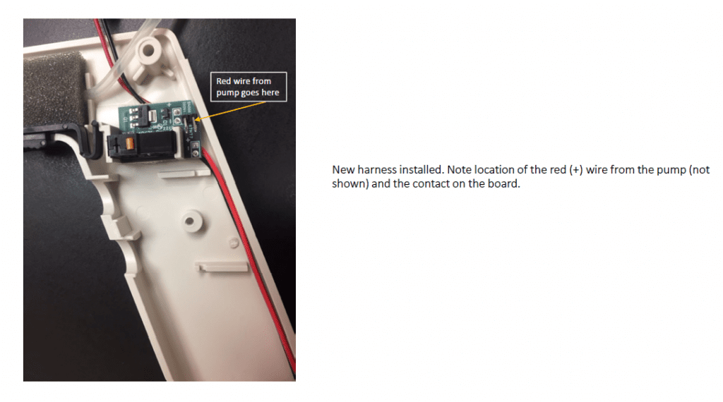
    new harness installed. note location of the red (+) wire from the pump (not shown) and the contact on the board.
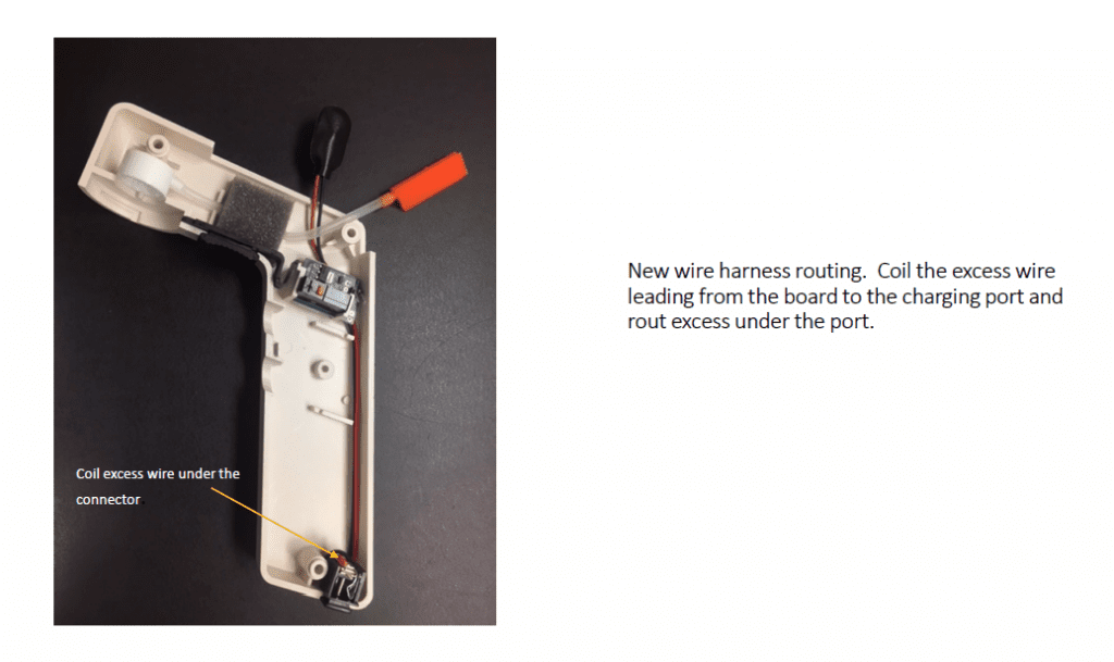
    New wire harness routing. Coil the excess wire leading from the board to the charging port and route excess under the port.
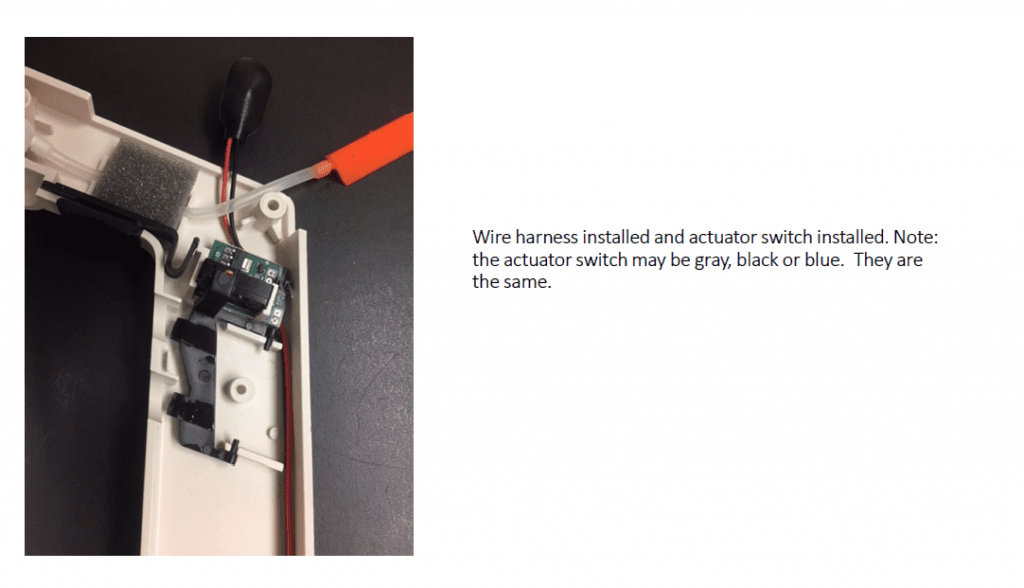
    Wire harness installed and actuator switch installed. Note: the actuator switch may be gray, black, or blue. They are the same.
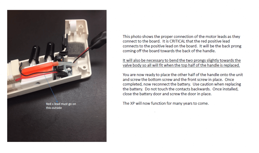
    This photo shows the proper connection of the motor leads as they connect to the board. It is critical that the red positive lead connects to the positive lead on the board. It will be the black prong coming off the board towards the back of the handle.
It will also be necessary to bend the two prongs slightly toward the valve body so all will fit when the top half of the handle is replaced.
Place the other half of the handle onto the unit and screw the bottom screw and the front screw in place. Once complete, reconnect the battery. Use caution when replacing the battery. Do not touch the contacts backwards. Once installed, close the battery door and screw the door in place.

    Disclaimer: Any action you take using the information on this website is strictly at your own risk. The information herein does not constitute professional advice and is general in nature. We make no warranty that this information will meet your requirements, be safe, accurate, or error-free. Pipette Supplies, Inc. is not responsible for any errors or omissions, any results obtained from the use of this information, or any loss or damage arising out of the use of this information. This site is for educational purposes only.
    Fair Use: Copyright Disclaimer under section 107 of the Copyright Act of 1976, allows for “fair use” for purposes such as comments, criticism, teaching, scholarship, news reporting, and research.
    Fair use is permitted by copyright statute that might otherwise be infringing.